In this post I have explained how to make a timer circuit for fitness, or gym workout application. The idea was requested by Mr. Jan.
Circuit Objectives and Requirements
I need a circuit diagram for a timer which is used in a fitness gym. It consists out of 5 x incandescent (5 channels) 220V colored bulbs which switch on in sequence, but stays on until the entire sequence is completed. It then resets and the entire sequence is repeated indefinitely.
In the gym the lights are used for circuit training. There are about 15 different exercises available. So the 15 people will each choose one of the 15 exercises. For instance you will select to do the cycling exercise, I will select the rowing exercise and so on until all 15 people have chosen a specific exercise to do. When the lights go green(channel 1) a beeper sounds and everybody start exercising until all four green(channel 1-4) lights are on. When the red(channel 5) light goes on a beeper will sound and you stop exercising. This is resting time and now you also change over to a different exercise. When the green light(channel 1) goes on again you start again. And so you continue until you drop dead. HA-HA
To sum up, this timer circuit for fitness gym application should function as follows:
1. Bulb No. 1 will go ON & stay ON for entire sequence
2. After approx. 20 sec Bulb No. 2 will go ON & stay ON for entire sequence
3. After approx. 40 sec Bulb No. 3 will go ON & stay ON for entire sequence
4. After approx. 60 sec Bulb No. 4 will go ON & stay ON for entire sequence
5. After approx. 80 sec Bulb No. 5 will go ON & stay ON for entire sequence
6. The unit will reset and repeat the sequence indefinitely
The overall timing should be adjustable. Not necessary to adjust individual channels.
The Circuit Diagram
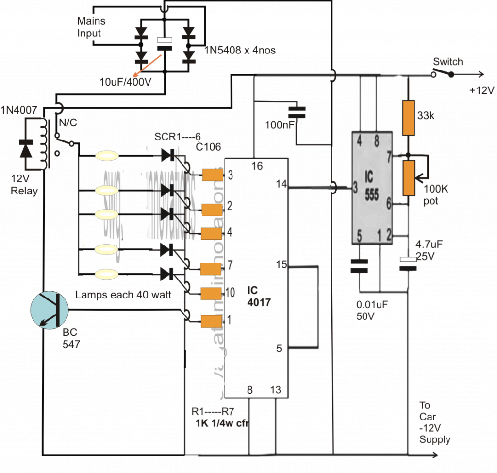
Warning: The Circuit is Not Isolated from Mains AC, and therefore is extremely dangerous to touch in an uncovered, switched ON position. Proceed with extreme caution while testing this circuit.


Questions & Answers
Thanks again Swagatam. It is just not working correctly. If I connect pin 7 of IC4017 to + of buzzer via 1N4007 the led’s from outputs 2 and 3 of IC4017 does not reset , they stay illuminated . If I connect only pin4 of 555 to pin 3 of IC4017 , I get a usable result. Everything works fine but the problem is that the 3 outputs from IC4017 are high for 14.5 seconds . If I use a 1000uF cap on the 555 I get 4 beeps during the period. The idea is that there should be 2 quick beeps exactly when output 3 (1st output) goes high and then no more. That audibly signals the start of the whole sequence. When pin7 of IC4017 goes high(last output) there should be a longer beep only once to signal the start of the changeover period. Output 10 of IC4017 resests the whole cycle since it is connected to pin15 of IC4017.
Hi Swagatam,
My apologies. I had the diodes connected incorrectly. All is functioning right now. Just a last problem though. Pin 3 (1st output) from IC4017 makes beeps for whole sequence and when pin7 of IC4017 goes high it causes one long beep for whole period. How do I control the beeps to limit how many times they beep during the period?
Hi David, Glad to hear its working now, for restricting the buzzer timing you can modify the diode section as shown in the following image
The value of the respective Capacitors and the associated resistors will decide the ON time length of the buzzer and could be determined with some trial and error.
Hi Swagatam ,
Many many thanks for the help but my friend says he doesn’t want any buzzers because the gym will be too noisy . Only lights. Is it possible to do simply this:
1. Pin 3 from 4017 outputs . 0-45 seconds mark. LED #1
2. Pin 2 from 4017 outputs. 15-45 seconds mark. LED #2
3. Pin 4 from 4017 outputs. 30-45 seconds mark. LED #3
So by the 45 seconds mark the first three LED’s are on. After 45 seconds they go off.
4. LED 4 comes on for 15 seconds from the 45-60 second mark. It will be nice if this LED could blink.
After the 60 second mark the whole process resets and LED #1 lights up again and so on…..
I will configure the 555 to make the periods 15 seconds .
Many many thanks in advance. My apologies for dragging this out this far.
Hi David, yes the mentioned specification can be easily achieved by adjusting the IC 555 frequency at 7.5 seconds ON/OFF rate.
Wish you all the best.
Hi Swagatam ,
Thanks a million for the help and patience , but this circuit simply does not function in the way I want. Pin 7 is connected to the base of T1 which means there is constant current flowing to pin 4 of the 555 and thus pin 3 of the 555. That means LED 4 is on all the time. It does not come on only when pin 7 starts to output during the 4017 sequence. As per your schematic the resistors on all 4017 outputs are 1K , maybe the resistor on pin 7 must be higher , I don’t know. The transistor just does not shut down completely. The voltage on the other outputs is 0.00V when not triggered and 0.9V when triggered. Pin 7 has a voltage of 9V even before it is triggered. That is why the LED4 stays on all the time. The 555 is getting power constantly and should only “start” up when pin7 triggers on the 4017. But maybe I’m just stupid. Many thanks anyway for the selfless help .Regards
Hi David,
T1 is a PNP so it is supposed to stay ON when pin#7 is OFF, and OFF when pin#7 is ON, so it is doing exactly what it should do.
Pin#4 of the IC 555 must be connected directly to pin#7, not to the base of T1 or after the resistor 1K at pin#7.
If you check pin#7 initially you will find it to be 0V, until the logic sequence reaches here.
And please remember if you want to measure the transistor’s base voltage you must do it by touching the meter prods across base/emitter, not to base ground, because it is a PNP.
So my IC555 suggestion for the flashing LED is correct….just make sure to connect pin#4 directly with pin#7 of 4017.
Hi Swagatam ,
Last try ! Something I don’t understand. Pin 7 on IC4017 is my last output that triggers the TIP127 transistor and shuts off the LED’s. Next up is pin 10 that resets the IC4017.If pin 7 is also connected to the positive of the 4th LED( used to be a buzzer) , the 4th LED is on all the time . Is the transistor giving current to this LED even though pin 7 of IC 4017 is not triggered? Should pin 7 of IC4017 be connected to both the the positive of the 4th LED and the base of TIP127?
What happens in effect if I just remove the second 555 and merely connect the 4th LED to pin 7 of IC4017 , I have 5 periods during my sequence. There should be 4 of 15 seconds each.
1. Pin 3 on for 15 seconds
2. Pin 2 on for 15 seconds
3. Pin 4 on for 15 seconds
4. Pin 7 on for 15 seconds
Now pin 10 becomes the triggering pin for TIP127 which adds another 15 seconds to the sequence. Pin 1 now becomes the reset. All in all 75 seconds.
Really sorry for wasting your time but I’m sure I am missing something here.
What should happen is this:
IC 4017
Pin 3 – outputs to 1st led – 15 seconds
Pin 2 – outputs to 2nd led – 15 seconds
Pin4 – outputs to 3rd led – 15 seconds
Now the first 3 led’s shuts off.
Pin7 – outputs to 4th led – 15 seconds ( I want this led to blink)
Entire sequence of 60 seconds restarts .
Hi David,
Let’s first remind the other readers that we are discussing the following circuit:
https://www.homemade-circuits.com/sequential-bar-graph-turn-light/
The required results can be simply achieved by connecting the resistor end of pin#7 with the base of T1. For flashing LEDs at this pinout, a separate IC 555 astable could be used with its pin#4 connected with pin#7, and the 4rth LED connected across its pin#3 and ground.
Finally the last pin in the sequence which is supposed to be pin#10 may be connected with pin#15 of the IC.
This modification will hopefully fulfill your present requirement
Hi David, pin#7 connection to the buzzer is perfectly isolated by the diode, therefore it cannot have any effect on anything else in the circuit. Moreover the buzzer itself is isolated from the other pinouts of the IC since the buzzer is not associated with anything except pin#7…. so it is difficult to understand how it can keep LeDs at pin#2 and pin#3 illuminated?? It will need to diagnosed deeper.
For ensuring just 2 beeps at pin#3 of 4017, this can be fixed by adding a capacitor in series with the pin#3 diode of IC 555…I’ll modify the diagram appropriately and let you know.
Can this circuit be powered by a 12V DC 1A power supply and what would the schematic look like then?
Hi Swagatam ,
I got it working at last . Works perfectly thank you. Just a couple of things. On my breadboard it makes no difference whether I connect pin4 of the 555 before or after the 1k resistor . I have it connected after the 1k resistor now . I just replaced the 1k with a 10k resistor and voila.
Hi David,
I am happy it worked, however not connecting pin#4 of IC 555 with pin#7 directly, rather connecting it with the base of T1 is technically incorrect.
Because the positive supply through the emitter of T1 would be continuously reaching the IC 555 pin#4, and this could reset the IC into activation.
Connecting pin#4 of IC 555 with pin#7 of IC 4017 will ensure that the IC555 is held inactive for so long as pin#7 does not become high in the sequence.
for 12V operation, you could do the modifications as shown in the following article
https://www.homemade-circuits.com/sequential-bar-graph-turn-light/
Thanks Swagatam. I cant get this circuit to work. I forgot to mention that the led’s should be high powered led’s with forward voltage of 3V and 350mA. Please help!
Hi David, referring to the following post
https://www.homemade-circuits.com/sequential-bar-graph-turn-light/
you can do the below mentioned mods for your 1 watt LEDs:
replace the SCR with C106 SCRs.
replace the 2N2907 with TIP127 on heatsink.
for the LED series resistors replace all of them with a 10 ohm 2 watt resistors.
That’s all.
Thanks Swagatam,
Works beautifully! Thanks for the help. Any ideas on how I can wire a piezo buzzer into the circuit maybe? I want a double short beep when output 3 ( the first obviously) triggers on the 4017 and a slightly longer single beep when the last output triggers (7 in my case) . I have 3 LED’s connected to 3,2 and 4.This is in case someone doesn’t face the lights and therefore there should be an audio cue to change stations in the gym.
Hi Swagatam ,
I can’t get the buzzer working in this one. I put together an astable circuit just like the other 555 timer. Pin 1 grounded , 2 connects with 6 , 3 outputs through a 1N4007 diode to the buzzer positive and the buzzer is also grounded . Pin 4 connects to 8 and pin 8 to +12V line. Pin 6 connects to 2 obviously and the capacitor and resistor to ground. Pin 7 connects to the two resistors just like in the other 555 setup. All copied over. Pin 5 grounds through a cap. Then I connect pin 4 of the 555 also to pin 3 of the IC4017 , which is the first pin that gets power in the sequence. Pin 7 of the IC4017 is also connected to the junction of 1N4007 and buzzer positive just like you instructed.
Am I missing something somewhere? Please help! I also have no idea how to configure the second 555 circuit to output 2 beeps only when pin 3 triggers on IC4017 and just one longer beep when pin 7 triggers on IC 4017.
Hi David, please check out the following diagram and configure the astable design in this manner:
R1, R2, ans C will need to be adjusted such that the astable produces around 2 pulses on the buzzer within the time slot provided by the pin#3 ON time of IC 4017…for example suppose pin#3 of IC 4017 sequences at a rate of 2 seconds, meaning pin#3 will be high for 2 seconds, therefore the astable should be adjusted to produce 2 pulses within this 2 second slot.
Let me know if you have further problems.
You can adjust R1, R2, C with the help of this software
https://www.homemade-circuits.com/ic-555-timer-astable-circuit-calculator/
Glad it worked David, thanks for updating the info.
For the buzzer you will have to make another IC 555 astable circuit similar to the existing one which is connected with the 4017 IC.
You will also need a piezo buzzer, and connect positive wire of the buzzer via a 1N4007 diode to pin#3 of this 555 IC and the negative wire to the ground line, and also connect pin#4 of this IC 555 with pin#3 of IC 4017, do not connect this pin#4 to anywhere else
Pin#7 of the IC 4017 may be directly connected to the buzzer positive wire directly (to the junction of buzzer positive wire and the cathode of the 1N4007)
All the negatives of the IC stages must be tied up together.
This new IC 555 astable should be tweaked such that it generates around 2 beeps for one sequence of the relevant pin of the IC 4017 (pin#3)
Let me know if you have any doubts
Hi Swagatam
About this project “Timer Circuit for Fitness Gym Application”.
A warning message must be written that mains is all over the circuit beacuse there is no isolation transformer.
Anyone tuching any component will suffer from the electric shock.
Your blog is very usefull and intersting ! Thanks.
Thank you Tal, I am glad you liked my site. and yes I have added the warning notification in the article.
Hi. I need to install a siren at a school, that goes off every 30minutes for 15seconds, from 8:00 in the morning until 15:00 in the afternoon.
Can u pls help me?
Hi, you can either try the following first configuration, and use it by manually for switching it ON once in the morning and manually switching it off in the evening, or use the second link for a complete automatic actions:
https://www.homemade-circuits.com/how-to-make-simple-programmable-timer/
https://www.homemade-circuits.com/automatic-programmable-school-bell/
Hello Swagatam,
I am big fan of your blog. I have tried many circuit and I have successful implemented water overflow circuit. which help me save 7300 ltr water per year.
Happy to write you again. My requirement is like, I want my wifi router should be switch off after 12 ( In Night) and switch on in morning 6 am. can you please provide any circuit for this.
Regards,
Prashant.
Thank you Prashant, I am really glad you are finding my circuits useful.
for the present requirement, you could try the following concept and set the respective pots for the required ON OFF intervals
https://www.homemade-circuits.com/how-to-make-simple-programmable-timer/