In this post I have explained a simple electronic load controller or governor circuit which automatically regulates and controls the rotational speed of a hydro-electric generator system by adding or deducting an array of dummy loads. The procedure ensures a stabilized voltage and frequency output for the user. The idea was requested by Mr. Aponso
Technical Specifications:
Thanks for reply and I was out of country for two weeks. Thanks for info and timer circuit is working very fine now.
Case II , I need electronic Load Controller(ELC)My hydro power plant is 5 kw single phase 220V and 50Hz and need to control excess power using ELC. Please give reliable circuit for my requirement
Aponso
The Design
If you are one of those lucky people who have a free flowing creek, river stream or even an active small water fall near your backyard, you can very well think of converting it into free electricity simply by installing a mini hydro generator in path of the water flow, and access free electricity for lifetime.
However the main problem with such systems is the speed of the generator which directly affects its voltage and frequency specs.
Here, the rotational speed of the generator depends on two factors, the power of the water flow and the load connected with the generator. If any of these alter, the speed of the generator too alters causing an equivalent decrease or increase in its output voltage and frequency.
As we all know that for many appliances are such as refrigerators, ACs, motors, drill machines, etc voltage and frequency can be crucial and may be directly related to their efficiency, thus any change in these parameters cannot be taken lightly.
In order to tackle the above situation so that the voltage and the frequency both are maintained within tolerable limits, an ELC or electronic load controller is normally employed with all hydro power systems.
Since controlling water flow cannot be a feasible option, controlling load in a calculated manner becomes the only way out for the above discussed issue.
This is in fact rather straightforward, it's all about employing a circuit which monitors the voltage of the generator and switches ON or OFF a few dummy loads which in turn control and compensate for the increase or decrease in the speed of the generator.
Two simple electronic load controller (ELC) circuits are discussed below (designed by me) which can be easily built at home and used for the proposed regulation of any mini hydro power station. I have explained their operations with the following points:
ELC Circuit using IC LM3915
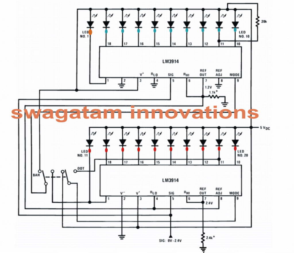
The first circuit which uses a couple of cascaded LM3914 or LM3915 ICs are basically configured as a 20 step voltage detector driver circuit.
A varying 0 to 2.5V DC input at its pin#5 produces an equivalent sequential response across the 20 outputs of the two ICs, starting from LED#1 to LED#20, meaning at 0.125V, the first LED lights up. while as the input reaches 2.5V, the 20th LED lights up (all LEDs lit up).
Anything in between results in toggling of the corresponding intermediate LED outputs.
Let's assume the generator to be with 220V/50Hz specs, means the lowering its speed would result in lowering of the specified voltage as well as the frequency, and vice versa.
In the proposed first ELC circuit, we reduce the 220V to the required low potential DC via a resistor divider network and feed pin#5 of the IC such that the first 10 LEDs (LED#1 and rest of the blue points) just illuminate.
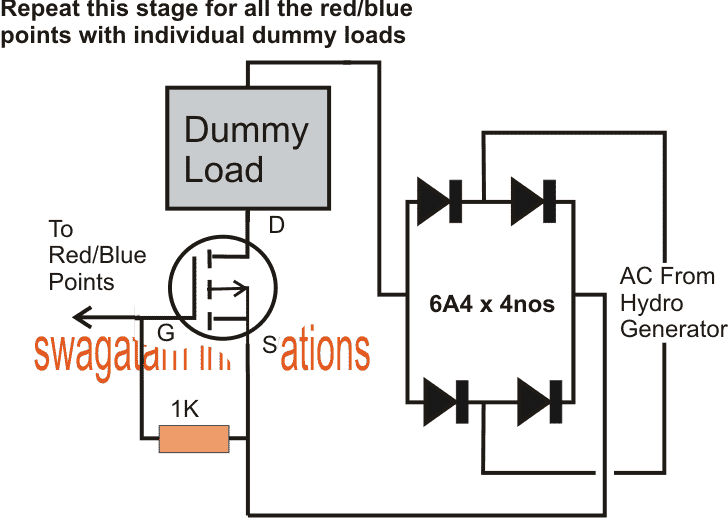
Now these LED pinouts (from LED#2 to LED#20) are also attached with individual dummy loads via individual mosfet drivers, in addition to the domestic load.
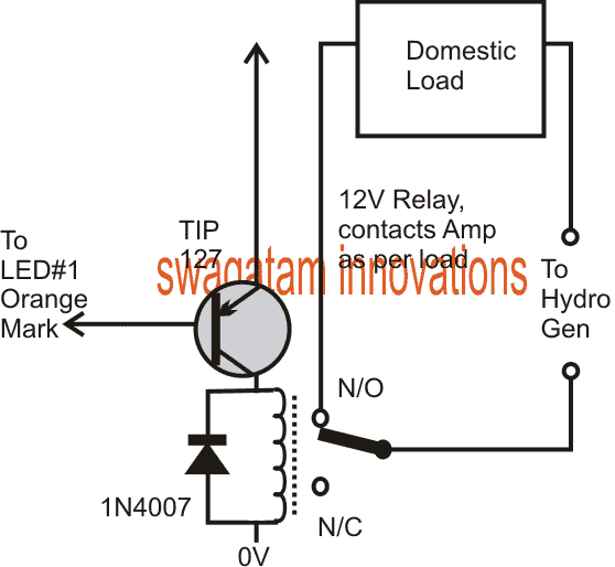
The domestic useful loads are connected via a relay on LED#1 output.
In the above condition it assures that at 220V while all the domestic loads are in use, 9 additional dummy loads also illuminate, and compensate to produce the required 220V @50Hz.
Now suppose the speed of the generator tends to rise above the 220V mark, this would influence pin#5 of the IC which would correspondingly switch the LEDs marked with red dots (from LED#11 and upwards).
As these LEDs are switched ON, the corresponding dummy loads get added to the fray thereby squeezing the speed of the generator such that it gets restored to its normal specs, as this happens the dummy loads are again switched OFF in back sequence, this goes on self-adjusting such that the speed of the motor never exceeds the normal ratings.
Next, suppose the motor speed tends to decreases due to lower water flow power, LEDs marked with blue start shutting off sequentially (starting from LED#10 and downward), this reduces the dummy loads and in turn relieves the motor from excess load thereby restoring its speed toward the original point, in the process the loads tend to switch ON/OFF sequentially in order to maintain the exact recommended speed of the generator motor.
The dummy loads may be selected as per user preference, and conditional specs. An increment of 200 watts on each LED output would probably be most favorable.
The dummy loads must be resistive in nature, such as 200 watt incandescent lamps or heater coils.
Circuit Diagram
ELC Circuit using PWM
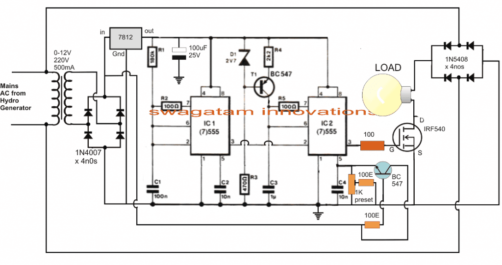
The second option is rather very interesting and even more simpler. As can be seen in the given diagram, a couple of 555 ICs are used as a PWM generator which alters its mark/space ration in response to the correspondingly varying voltage level fed at pin#5 of IC2.
A well calculated high wattage dummy load is attached with a sole mosfet controller stage at pin#3 of IC#2.
As discussed in the above section, here too a lower sample DC voltage corresponding to 220V is applied at pin#5 of IC2 such that the dummy loads illuminations adjust with the domestic loads to hold the generator output within the 220V range.
Now suppose the rotational speed of the generator drifts towards the higher side, would create an equivalent rise in potential at pin#5 of IC2 which in turn would give rise to higher mark ratio to the mosfet, allowing it to conduct more current to the load.
With increase in the load current, the motor would find it harder to rotate thus settling down back to its original speed.
Exactly the opposite happens when the speed tends to drift toward lower levels, when the dummy load is weakened in order to pull up the speed of the motor to its normal specs.
A constant "tug-of-war" continues so that the speed of the motor never shifts too much from its required specifications.
The above ELC circuits can be used with all types of microhydro systems, watermill systems and also wind mill systems.
Now let's see how we can employ a similar ELC circuit for regulating the speed and frequency of a windmill generator unit. The idea was requested by Mr. Nilesh Patil.
Technical Specifications
I am Great fan of your Electronic circuits and Hobby to create it. Basically i'm from rural area where 15 hours power cut off problem we facing every year
Even if i go for to buy inverter that is also not get charged due to power failure.
I have created wind mill generator (In Very Cheap Cost ) from that will support to charge 12 v battery.
For the same i m looking to buy wind mill charge turbine Controller that is too costly.
So planned to create our own if have suitable design from you
Generator Capacity : 0 - 230 AC Volt
input 0 - 230 v AC (Vary depends on wind speed)
output : 12 V DC (sufficient boost up current).
Overload / Discharge / Dummy Load handling
Can you please suggest or help me to develop it and required component & PCB from you
I May required many same circuit once succeed.
The Design
The design requested above can be implemented simply by using a step down transformer and a LM338 regulator as already discussed in many of my posts earlier.
The circuit design I have explained below is not relevant to the above request, rather addresses a much complex issue in situations where a windmill generator is used for operating AC loads assigned with mains 50Hz or 60Hz frequency specifications.
How an ELC Works
An electronic load controller is a device which frees or chokes up the speed of an associated electricity generator motor by adjusting the switching of a group of dummy or dump loads connected parallel with the actual usable loads.
The above operations become necessary because the concerned generator may be driven by an irregular, varying source such as a flowing water from a creek, river, waterfall or through wind.
Since the above forces could vary significantly depending upon the associated parameters governing their magnitudes, the generator could also be forced to increase or decrease its speed accordingly.
An increase in speed would mean an increase in voltage and frequency which in turn could be subjected to the connected loads, causing undesirable effects and damage to the loads.
Adding Dump Loads
By adding or deducting external loads (dump loads) across the generator, its speed could be effectively countered against the forced source energy such that the generator speed is maintained approximately to the specified levels of frequency and voltage.
I have already discussed a simple and effective electronic load controller circuit in one of my previous posts, the present idea is inspired from it and is quite similar to that design.
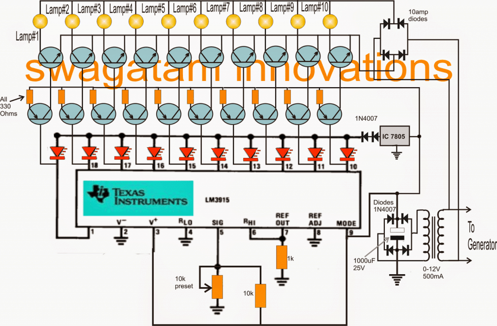
The figure below shows how the proposed ELC may be configured.
The heart of the circuit is the IC LM3915 which is basically a dot/bar LED driver used for displaying variations in the fed analogue voltage input through sequential LED illuminations.
The above function of the IC has been exploited here for implementing the ELC functions.
The generator 220V is first stepped down to 12V DC through a step down transformer and is used for powering the electronic circuit consisting the IC LM3915 and the associated network.
This rectified voltage is also fed to pin#5 of the IC which is the sensing input of the IC.
Generating Proportionate Sensing Voltages
If we assume the 12V from the transformer to be proportionate with 240V from the generator, implies that if the generator voltage rises to 250V would increase the 12V from the transformer proportionately to:
12/x = 240/250
x = 12.5V
Similarly if the generator voltage drops to 220V would proportionately drop the transformer voltage to:
12/x = 240/220
x = 11V
and so on.
The above calculations clearly show that the RPM, frequency and voltage of the generator are extremely linear and proportionate to each other.
In the proposed electronic load controller circuit design below, the rectified voltage fed to pin#5 of the IC is adjusted such that with all the usable loads switched ON, only three dummy loads: lamp#1, lamp#2 and lamp#3 are allowed to remain switched ON.
This becomes a reasonably controlled set up for the load controller, of course the adjustment variations range could be set up and adjusted to different magnitudes depending upon the users preferences and specifications.
This may be done by randomly adjusting the given preset at pin#5 of the IC or by using different sets of loads across the 10 outputs of the IC.
Setting up the ELC
Now with the above mentioned set-up let's assume the generator to be running at 240V/50Hz with the first three lamps in the IC sequence switched ON, and also all the external usable loads (appliances) switched ON.
Under this situation if a few of the appliances are switched OFF would relieve the generator from some load resulting in an increase in its speed, however the increase in the speed would also create an proportionate increase in voltage at pin#5 of the IC.
This will prompt the IC to switch ON its subsequent pinouts in the order thereby switching ON may be lamp#4,5,6 and so on until the speed of the generator is choked up in order to sustain the desired assigned speed and frequency.
Conversely, suppose if the generator speed tends to sow down due to degrading source energy conditions would prompt the IC to switch OFF lamp#1,2,3 one by one or a few of them in order to prevent the voltage from falling below the set, correct specifications.
The dummy loads are all terminated sequentially via PNP buffer transistor stages and the subsequent NPN power transistor stages.
All the PNP transistors are 2N2907 while the NPN are TIP152, which could be replaced with N-mosfets such as IRF840.
Since the above mentioned devices work only with DC, the generator output is suitably converted to DC via 10amp diode bridge for the required switching.
The lamps could be 200 watt rated, 500 watt rated or as preferred by the user, and the generator specs.
Circuit Diagram
So far I have explained an effective electronic load controller circuit using a sequential multiple dummy load switcher concept, here I have explained a much simpler design of the same using a triac dimmer concept and with a single load.
What's a Dimmer Switch
A dimmer switch device is something we all are familiar with and can see them installed in our homes, offices, shops, malls etc.
A dimmer switch is a mains operated electronic device which can be used for controlling an attached load such as lights and fans simply by varying an associated variable resistance called a pot.
The control is basically done by a triac which is forced to switch with an induced time delay frequency such that it remains ON only during a fraction of the AC half cycles.
This switching delay is proportionate with the adjusted pot resistance and changes as the pot resistance is varied.
Thus if the pot resistance is made low, the triac is allowed to conduct for a longer time interval across the phase cycles which allows more current to pass through the load, and this in turn allows the load to activate with more power.
Conversely if the pot resistance is reduced, the triac is restricted to conduct proportionately for a much smaller section of the phase cycle, making the load weaker with its activation.
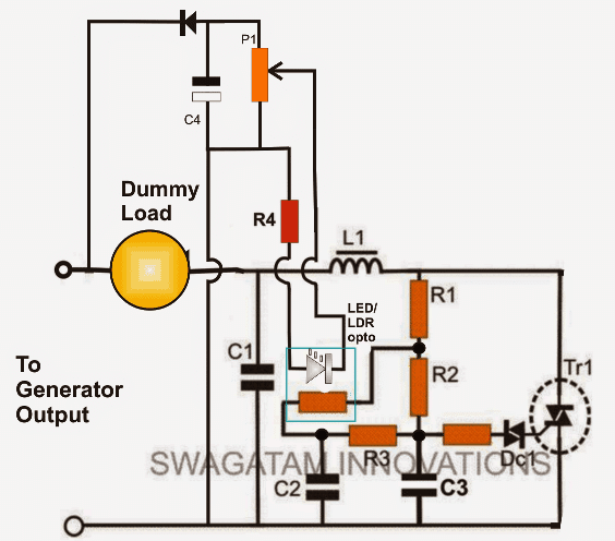
In the proposed electronic load controller circuit the same concept is applied, however here the pot is replaced with an opto coupler made by concealing an LED/LDR assembly inside a light proof sealed enclosure.
Using Dimmer Switch as ELC
The concept is actually pretty simple:
The LED inside the opto is driven by a proportionately dropped voltage derived from the generator output, meaning the LED brightness now is dependent on the voltage variations of the generator.
The resistance which is responsible for influencing the triac conduction is substituted by the LDR inside the opto assembly, meaning the LED brightness levels now becomes responsible for adjusting the triac conduction levels.
Initially, the ELC circuit is applied with a voltage from the generator running at 20% more speed than its correct specified rate.
A reasonably calculated dummy load is attached in series with the ELC, and P1 is adjusted such that the dummy load slightly illuminates and adjusts the generator speed and frequency to the correct level as per the required specs.
This is executed with all the external appliances in a switched ON position, that may be associated with the generator power.
The above implementation sets up the controller optimally for tackling any discrepancy created in the speed of the generator.
Now suppose, if a few of the appliances are switched OFF, this would create a low pressure on the generator forcing it to spin faster and generate more electricity.
However this would also force the LED inside the opto to grow proportionately brighter, which in turn would decrease the LDR resistance, thereby forcing the triac to conduct more and drain the excess voltage through the dummy load proportionately.
The dummy load which is obviously an incandescent lamp could be seen glowing relatively brighter in this situation, draining the extra power generated by the generator and restoring the generator speed to its original RPM.
Circuit Diagram
Parts List for the single dummy load, electronic load controller circuit
- R1 = 15K,
- R2 = 330K
- R3 = 33K
- R4 = 47K 2 WATT
- R5 = 47 OHMS
- P1 = 100K 1 WATT PRESET
- C1 = 0.1uF/1KV
- C2,c3 = 0.047uF/250V
- OPTO = ASSEMBLY OF WHITE HIGH BRIGHT 5MM LED, AND A SUITABLE LDR
- L1 = 100mH, 20 AMP FERRITE CORE INDUCTOR
- DUMMY LOAD = 2000 WATT LAMP
- DC= DIAC DB-3 BIG
- TR1 = TRIAC BTA41/600


Questions & Answers
Hi Swagatam,
am doing project on automatic temperature control system that uses both K type thermocouple and operational amplifiers in a greenhouse . am an engineering student. The circuit has an indicator when the temperature has risen above 29℃ or fallen below 27℃. can you please help me with the circuit and all.please…
Hi Kesy,
You can refer to the following post and take the help of the design for your application:
https://www.homemade-circuits.com/2011/12/make-simple-refrigerator-thermostat.html
nice post sir !
love it
You are welcome Tushar.
Hi sir,
I need a help in relation to my final year project.It is concerned with creating a micro model of a hydro power generation system.Is there any way to regulate the output voltage of an alternator according to a dip or fall in speed.is there any small alernator(12 v range) that i can use?
Hi Arjun,
You can use a bicycle dynamo for this project, and for the frequency control circuit you can try the first circuit provided in the above article.
for feeding the input of the LM3915 you can calculate the required resistor deivider network with the help of any online "potential divider calculator" software.
The load wattage selection will need to be done through trial and error and by experimentation.
for the pwm circuit, apply 220V from the generator across the bridge and adjusted the 10K preset such that the dummy load adjusts to negotiate this voltage and doesn't drop this voltage any further.
pls click the diagram to enlarge, all the parts value could be seen in the diagram itself.
The second picture the one with the domestic load didnt catch that where does that fit in?
and what is the part in the first circuit Where it is written 'bar' and 'dot'
Thanks a lot for support
the arrow head will go to the positive supply of the circuit, the base to the orange terminal of the IC (first terminal).
the dot/bar selector is a DPDT switch.
the switch can be used for selecting bar mode or dot mode, in bar mode all leds in the relevant level will light up sequentially giving a rising bar like appearance, whereas in dot mode only one led will be lit at the the particular instantaneous level producing a dot like of indication.
all the information is given in the diagram itself, please check it again.
the LM3915 circuit will require a 12V supply which can supplied through a standard ac/dc 12V adapter using a 0-12V/500ma transformer
I could not understand your question, are you referring to a hydrogen powered generator??
its output would be as good as a normal 220V domestic AC….
yes three different sections will need to be integrated together as per the given instruction….in fact each pin of the IC will include individual mosfet stages and the loads.
Good day sir! sir may i ask a few questions about the ELC. sir why is that our ELC becomes load instead of dummy load?.when we connect the ELC to the micro hydro system, it consumes the power from the generator and only few power can reach the consumers…?thank you and God bless!!
Good day Roger,
It's probably the only feasible and simple method of keeping the motor speed and frequency constant irrespective of the varying waterfall force.
what is the use of 547 along with the zener at pin 6 and 7 (through 100 ohm resistor) at the 2nd 555 of the above elc ckt (last diagramme)?? please explain… thanks
it should be BC557 actually, it's for providing a constant current to the pin6/7 so that the IC can respond correctly even under varying voltages.
sir,
Whats the MOSFET used in the switching circuit?
you can use IRF840
Sir',
What is the type of load used in the MOSFET switching module? Is it ac or DC load? And what is the use of of the rectifier with the 6A4 diodes? What does the "bar" dot. Component do and signify.
Thank you for your wonderful support
The load can be any resistive load, such as incandescent bulbs, heater coils etc.
mosfets work with DC therefore supply is given through a bridge rectifier.
bar mode produces the output sequence in the form of latched outputs, whereas the dot mode shuts the sequence as it proceeds along the output pin sequence
Sir,
The MOSFET IRF480 requires a gate voltage of 3.6V to trigger but the IC output is only 1.9V is there an alternative MOSFET that can be used? and also is there any alternative power diode that can replace 6A4 diodes. Thank you as always for your support.
Riyaz, in that case you can replace the mosfet with a PNP transistor and relay stage. The relay contact can be wired with the dummy loads.
If you don't want to use a relay then simply join the collector of the PNP with the gate of a N-mosfet (IRF540)….also dont forget to terminate the junction with a 1k resistor to ground.
6A4 can be replaced by any 6amp diode or more.
Interesting circuit.
I wish all your writeup as well as the schematics are made printable ! (pdf/rtf etc)
thanks, will try to present it in that form soon.
Hi swagatam thanks for amazing circuits.
i have a question. the dump load can be normal incandescent bulbs of specific wattage. the dump load switching will be in steps for example 40W , 100W and so on. so there is possibility that voltage might not be exact 220V. how to obtain continuous variation in the dump load for exact 220V?
Hi Ankit, the dump loads should be of equal wattage across all the outputs of the IC, the range of the system could be increased or decreased as per the specs either by equally increasing the lamp wattage and vice versa…for large hydro motors large bulbs could be used and for smaller motors smaller bulbs, and so on.
this will ensure a constant voltage and frequency from the system.
thank u swatagam. could u please send a more clear image of the circuit using ic 555 ?? because the values of all the components cannot be read out or else could you please provide me with the values individually? thank you.
Ankit, please click on the diagram to get an enlarged view of it and the enclosed details….the BC547 for the PNP is wrongly printed, please use a BC557 instead.
Hi
I need your assistant to develop this frequency base and at least three dummy loads can you support me with out relays
Cheers
chandana
Dear Swagatam
can u improve this ELC for few dummy loads
Dear Chandana,
for fewer dummy loads you can use a single LM3915 IC and configure it identically….you can refer to the datasheet of the IC for getting more info regarding its working principle…
;;
hello Swagatam,
it's can used for generator with avr/automatic voltage egulator.
hello mant7,
it is not recommended for diesel generators, it's suitable only for hydro generators.
sir, i need c language programming code to make electronic load controller using ATMega32
presently I do not have it, if i get i'll surely let you know.
Would the second ELC design with the IC 555 timer work when the generator is equipped with an Automatic Voltage Regulator?
I suspect it would not since the voltage is kept constant by the AVR while the ELC design is expecting changes in voltage.
if the 555 section is powered with a feed directly from the alternator, then it would work, and anyway the above circuits are intended to work with the supply from the alternator directly.
can you help me to design a governing circuit that controls the speed of turbine by water flow regulation???
controlling water flow can be quite complex, a better idea is to control the motor speed by shunting its excess current
Dear Sir thanks for this very nice circuit,The second option ELC
I have some questions. How do you power the +12vdc side?
The diode AC Mains Have earth on the left side is that correct?
On the AC Mains input is that from the Hydro gen Line and Neutral?
Dear Johan, you can get the 12V by using 0-12V/220V transformer and connecting it with the hydro generator output. The 12V AC will need to be rectified using a separate bridge rectifier and capacitor.
the indicated bridge rectifier is for the mosfet load and needs to be made using high power diodes, and yes its left side should be connected with the negative of the circuit, or the mosfet source pin.
the AC input is from the hydro AC
Hi
if i connect the first three circuits or uses the second option of 555 timer ic ….which circuit will give the most accurate result???
Hi, the last circuit looks more advanced and compact, you can it try it
sir
can you give you the pcb of the circuit which uses lm3914ics in a single board
Ravi, sorry PCB is not available at the moment.
sorry that cannot be possible, if the motor speed itself is below the intended limit, then there's no way it could be rectified, unless some smart circuit is employed