Optimizing power by tracking is the key feature which makes solar MPPT concept so unique and efficient, where the complex and non-linear I/V curve of the solar panel is tracked and switched for creating maximum optimal conditions for the connected load.
The Circuit Concept
I have been trying hard to design something that would in true sense track the I/V curve or the power curve of the panel, and correct it automatically whenever it drifts from the optimal points.The proposed design is based on the same grounds, but here I have included only the I (current) tracking stage in order to keep things simple. Actually it's the current that really matters and is directly proportional to power of the panel so I thought keeping this parameter in control could fulfill the job.
Let's try to understand the design with the following observations:
How the Circuit Functions
Looking at the proposed solar MPPT I/V curve tracker circuit diagram, the BC547 at the extreme right along with the 10k resistor and 1uF capacitor forms a linear ramp generator.
The central stage comprising the two 555 ICs form a variable PWM controlled output generator, while the IC 741 stage becomes the actual current tracker stage.
When the voltage from the solar panel connects across the BC547 collector and ground, due to the presence of the base 10k/1uf network, the emitter follower provides a gently rising voltage to the 555 PWM generator stage.
The ramp activates IC2 and forces it to generate a correspondingly rising PWM output at its pin#3 which goes to the gate of the driver mosfet.
The mosfet responds to these pulses and gradually increases its conduction and provides current to the battery in the same incremental order.
As soon as the current intake across the battery begins rising, an equivalent voltage level is translated across the current sensing resistor Rx which gets applied a pin#3 of the 741 IC.
The above potential also hits pin#2 of 741 via the dropping 1N4148 diode so that pin#2 follows this potential in tandem with pin#3 but lags behind by about 0.6V due to the presence of the series diode.
The above condition allows the opamp to begin with a high output which keeps the diodes at its pin#6 reverse biased.
As long as the current keeps climbing with the ramp, opamp pin#3 continues to be higher than pin#2, thus keeping the output higher.
However at some point of time, which might be after the I/V curve has just crossed, the current output from the panel starts dropping or rather drops abruptly across Rx.
This is sensed by pin#3 immediately, however due to the presence of the 33u capacitor, pin#2 is unable to sense and follow this drop in potential.
The above situation instantly forces the pin#3 voltage to become lower than pin#2, which in turn reverts the output of the IC to zero, forward biasing the connected diode.
The base of the ramp generator BC547 is dragged to zero forcing it to switch OFF, and reset the whole procedure back to the original state. The process now begins afresh.
The above procedure continues and ensures that the current is never allowed to fall or cross the inefficient region of the I/V curve.
This is just an assumption, a concept which I have tried to implement, it might require a lot many tweaking and alignments before it can become truly result oriented.
The output from the mosfet may be integrated with an SMPS based converter for even higher efficiency.
![]()


Questions & Answers
Dear sir,
I have a 50W solar battery (21V). In sunny weather it produces about 2A at 20V., but if the weather is cloudly, it provides very small energy (30-100mA). When I try to increase the load it drops to zero. Due to the lack of electricity at the installation site, even this small energy has the great importance to me. I have an idea to make a simple circuit that would collect energy on a storage capacitor that is connected directly to the solar panel and then discharge it to the battery when the the capacitor voltage reaches a certain level. This circuit must collect and release energy in portions to a 12-volt battery.
What do you think about this idea? It might be you have an information about?
Please answer to my E-mail.
With best regards,
Anatolii
Anatolii. Please look up a circuit called a mini maximizer for what you are trying to acomplish. It dumps a charged capacitor to charge a battery from a weak input. It can collect energy thats unusable or wasted.
Thank you Anatoli, for posting this interesting question.
Yes, that seems to be a very good idea.
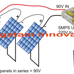
Here’s an example circuit design that you can try implementing. You can replace the BC557 transistor with a more powerful variant such as BD139 or TIP31 etc for handling higher current. The zener diode value determines the maximum charge level at which the dumping should happen.
Please add a 100uF capacitor across base/ground of the BC547 to trigger a full discharge of the super capacitor..
think you
i Have charger controller 100 v, 100 A can connected my power supply 80 v 20 amp
Yes, you can connect your 80V 20 amp power supply with your 100V 100 A charger controller.
Sorry, I cannot understand what you are trying to say??
do I have a source from 70 volts 20 amperes, how to use this source without danger?
Sorry, I cannot understand your question.
sorry, i have French, my translator is t not correct. nun the correct.
i have a source by 80volts and 20Amp. can I connect it without any probleme? what must i change? thank you.
No problem, your English is correct but I needed more details to understand, I have understood now.
The MOSFET decides how much current the circuit can supply to the battery.
So the MOSFET voltage and current must be rated appropriately to handle 80V 20 amp current.
The MOSFET can be an IRF540 to handle 80V 20 amps
However, please note that this circuit has not been tested by me, it is designed only with my assumptions.
Think you for your answers, i want connect , also, i change only the mosfet. i will experiment thank
You are welcome!
i think, a IRF 5210 i kann 80v at the entrance.
Yes this mosfet will also work.
But kindly remember that the above circuit has not been verified or tested by me.
is ok, sink you
Sure Lubo, you are most welcome!
Hi, I have a kind of MPPT desin published in this website, you can find it below
https://www.homemade-circuits.com/2015/11/simple-solar-mppt-circuit-part-2.html
instead you can simply incorporate a buck converter in order to generate electricity more efficiently.
If turning the solar panel manually according to the sun rays is possible, then you could also think about the following design with great efficiency….
https://www.homemade-circuits.com/2013/04/solar-water-heater-with-battery-charger.html
Hi, an MPPT can be much complex to build, instead you can simply hook up the coils directly with panel's output.
by the way a more sensible approach would be to use concave mirrors for the heating purpose…
If you compare the input and output power levels, you will find it to be equal, in short the MPPT power can never exceed the panel power output.
The voltage tracker stage will be also simiar to the current tracker stage except the input supply which will be received from the emitter follower at pin#5 of IC2, the diode cathode outputs of the two opamps may be then made into and connected with the 547 base, however as discussed in one of my posts an MPPT will be most efficient when its output is isolated and dropped via an SMPS circuit.
thank u for your reply. Why I asked about inreasing the current is when u look on the display of say an outback mppt display u see incoming current say 10amps and out current say 15amps so i thought the mppt controler was increasing the the incoming current. i am now confused with what to build because u are saying adding another 741 as voltage tracer would help. Should we wait until u complete that part of the circuit because I am sure there are a lot of people folowing your links on making a mppt controller we need a final circuit please help us here Mr Swagatam
Hello Chirag,
I'll try to design it, and post it soon.
Mr Swagatam I have been following ur post for months especially on the mppt controllers i appreciate ur improvement here. The operation sounds complex but I am willing to give it a try. So will this controller increase the current that the panel is putting out
No MPPT in this world can increase current, they are designed only for extracting the most from the panel in terms of voltage and current, it can never exceed the instantaneous maximum current production of the particular panel.
If you can make the 741 work correctly then it's done, you would definitely be able to make the above circuit work as per the expectations.
I think an identical 741 voltage tracker also needs to be added here, because tracing and optimizing voltage of the panel is also crucial.