In this post I have explained a remote controlled automatic transfer switch for enabling an automatic grid to generator changeover action from a specified distance. The idea was requested by Mr. odudu johnson.
Technical Specifications
Project description: Automatic changeover switch with wireless generator control abilities or mechanism.The generator rating is going to be between 2.2kva up to 2.5kva, and much be an automatic embedded systems generator on its own not the manual gen set...Single phase generator and the Mains will be single phase too.. Ie 220 volts 50hz..... The system will be designed to select between two available source of power Giving preference or priority to one out of the two sources of power. In this case, the selection is between public supply Mains and generator.The ATS should monitor the Mains supply and check for complete failure or power outage upon which it changes the load over to the generator supply, sends command to the generator wirelessly to start ie ON..And when the public supply is restored the ATS detects this sends an off command to the generator wirelessly the return the load back to the Mains............The communication between the ATS and Mains isn't wireless just that of the gen set.....I'll be expecting something positive
The Design
The entire design of the proposed remote controlled wireless generator automatic transfer switch circuit can be divided into the following explained 4 stages:
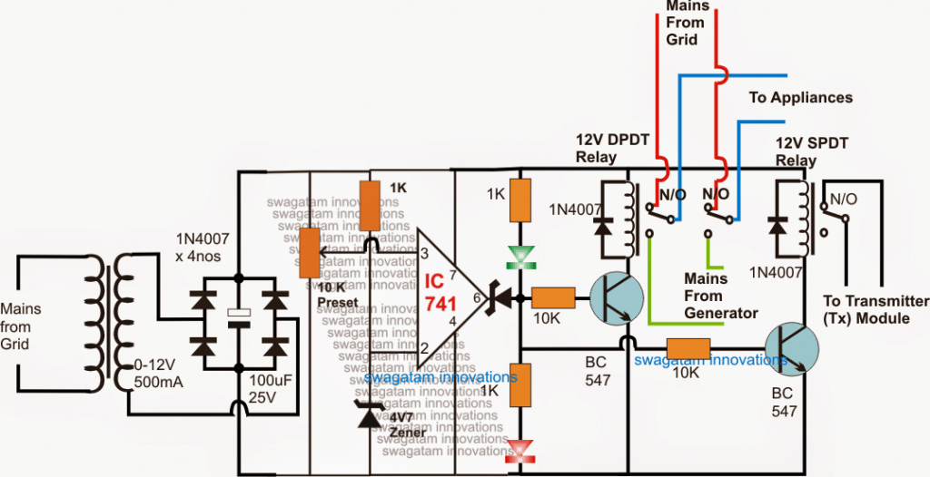
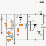
1) Low voltage (brownout), Grid failure detector changeover circuit:
The following circuit controls the mains ATS by detecting a possible grid low voltage condition or a complete failure. The opamp is configured as a comparator, wherein its non-inverting pin is used as the detector input via an adjustable 10k preset.
As long as the grid mains voltage is within the normal range the output of the opamp remains high, keeping the two relay driver stages switched ON.
The first relay changeover stage comprises a DPDT relay and it forms the main ATS grid to generator changeover controller relay, while the other smaller relay becomes responsible for controlling the transmitter circuit.
While the grid mains is active, both the relays stay activated, the DPDT supplies the grid AC to the home appliances through the relevant N/O contacts. The SPDT relay keeps the transmitter (Tx) circuit switched ON so that a continuous wireless signal is sent in the atmosphere for the Rx (receiver) circuit, which is supposed to be attached with generator system somewhere in the vicinity.
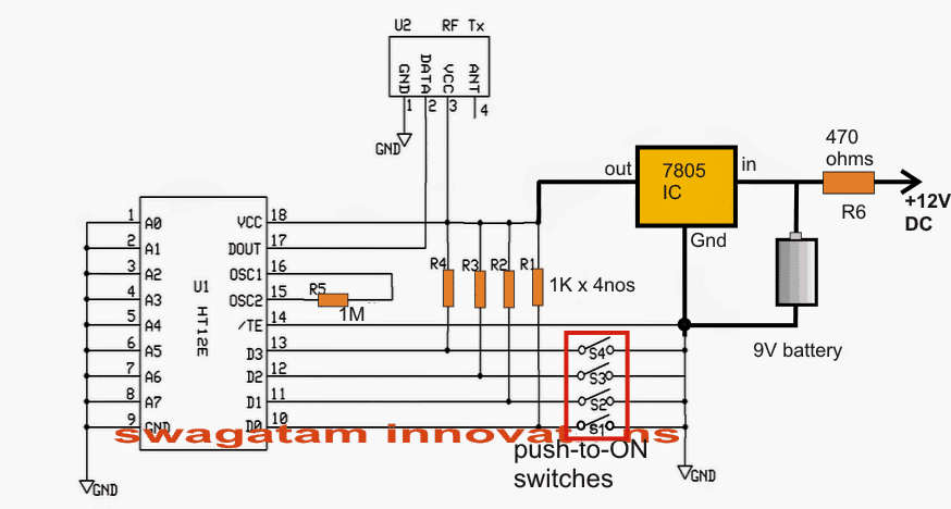
2) The Transmitter (Tx) Circuit:
The following diagram depicts the transmitter (Tx). The N/O contact connections from the above shown SPDT relay is connected across any one of the 4 switches (as desired)..... that is any one among the shown SW1---SW4 switches
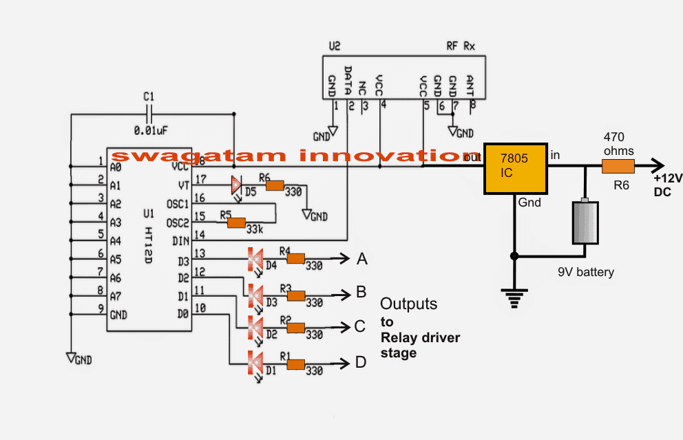
3) The Receiver Circuit (Rx):
The next diagram which may be witnessed below, is the receiver (Rx) circuit, which is positioned near the generator system and is configured to respond to the above shown Tx signals and keep the generator either ON or OFF, depending upon the grid mains availability.
When the grid mains is present, one of the selected switches (SW1----SW4) from the above Tx circuit is toggled ON by the SPDT relay in the first opamp circuit.
The wireless remote signals from the Tx unit is detected by the below shown Rx circuit, resulting in a low logic signal across one of the 4 outputs (A-----D) corresponding to the particular selected input of the Tx circuit (SW1----SW4), as selected.
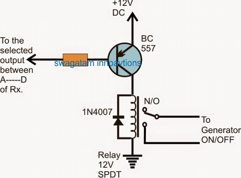
4) The Relay Driver Stage
The following shown relay driver stage is used to respond to the above discussed Rx circuit output's low logic and activate a connected relay.
As long as the selected output of the receiver (Rx) circuit remains ON, the BC557 from the below given relay driver stage also stays ON, keeping the associated relay activated, this is supposed to happen while the grid mains is available.
As indicated below, the relay stays switched ON across its N/O contacts which in turns keeps the generator switched OFF.
However in an event of possible low grid voltage or a complete failure, the opamps controlled ATS relays reverts to the N/C contacts, toggling the load towards the generator side of the changeover, and simultaneously the transmitter circuit is switched OFF.
With no signal available for the Rx unit, the corresponding relay driver stage and the relay are also switched OFF. The relay contacts now shift to its N/C contact enabling the generator with a switch ON power.
The generator is thus switched ON and the power to the appliances is supplied and changed over by the generator mains AC, via the ATS DPDT relay contacts from the opamp circuit.


Questions & Answers
I need a circuit diagram of ATS with remote control……and explanation
Thanks for the explanations,
I have also done some works in the area of automatic change over system. I have a very important question…..
How do you control the chock when using a wired or wireless generator remote control system?
I think I have addressed the issue in the following article:
https://www.homemade-circuits.com/automatic-transfer-switch-ats-circuit/
I need to simulate a circuit, ATS for a small portable generator, for my last project. Can I use this circuit or do you have another I can use?
Yes you can try it but only if you have understood the working of the design correctly.
Hi Swagatham , I hope my idea is not too ambitious, I am working on a DC Generator for the Solar Off Grid System,A small lawn mower generator hooked with a 12,24v alternator to charge the battery bank, however this need to be automated.
This ATS circuit comes handy , was just wondering if I can
1. Power the transmiter circuit with my solar system 12v ,
2.Trigger the transmiter to start/stop the gen from voltmeter , if the battery reaches 11.7V gen start and when it reaches 14.1v it stops
3.the receiver circuit remains the same
let me know what i may haave to change on the circuiit to achieve my goal ,
thanks in advance
Hi Vhafuwi,
yes all those mentioned points can be implemented using a 433MHz remote control module.
I guess no changes would be required and you can accustom the same design for your application also.
I am looking for an ATS that can be triggered by a relay rather than by the loss of power from the grid.
Can your diagram above be modified to provide for the relay and not the loss of power as the trigger for the switch to be activated?
You can simply eliminate everything in the first circuit except the extreme right side BC547/relay stage.
the trigger can be applied at the 10K end of the BC547. As long as this trigger is present the generator at the remote end will be switched OFF, and switch ON as soon as the trigger is removed.
Hello boss, the circuit hav been giving issues, one why did u use a 12v relay can that carry 220volts 50hz Mains or even that of the generator….. 2….what is the starting process involved with the generator in terms of the starting relay…… Please can I get a block diagram of the entire circuitry…… More information about it can still be posted because this is like my final year project report and it's important to know durin construction…. Thankzzz boss
…the relay contact rating needs to be matched with the load specs….
hello boss,
that would be difficult for me due to lack of time, Im busy with many pending assignments..
Thanks boss. Please what is the component labelled U2 in both Tx and Rx stages?
those are decoder/encoder ICs for the respective modules
can the decoder ICS be programmed using Arduino Nano?
sorry I have no idea about it!
Nice boss still yet to simulate the circuit
my pleasure boss, go ahead…
Thankzzz boss…….. Am yet to study the circuit…
Hello sir, i want to design a remotely controlled automated phase selector changeover switch, but am a bit confused putting it together. what should be the component parts, also is it going to be feasible, i want it to perform the following features:
• You can switch On/Off your generator with a remote control from any part of your house.
• No one needs to attend to the generator and manual changeover especially in odd hours.
• The product automatically switches off your Generator immediately power on the utility grid (NEPA) is restored.
• No one needs to worry about changing between NEPA and Generator anymore.
• Works on auto-mode principle (i.e. Generator can starts on itself own immediately power on the utility grid interrupted).
• Suitable for single phase petrol generators up to 20KVA (100A current rating)
• Easy to install, 12months warranty, 24/7 customer support
• Ultra fast changeover; No power interruption during changeover. Your gadgets will not go off
• Auto-stops generator when there’s main power supply (PHCN) and changes over immediately
• Auto-starts generator when there’s power failure and auto start mode is enabled.
• Users can start and stop their generator from the comfort of their room via a start and stop switch on the device
• Start function only Works for key start and automatic choke generators (automatic choke is a common feature on remote controlled generators)
• Auto-stop and button stop functions works for all class of domestic generators
• Allows users to time their generator for desired hours of operation,
• Timing should be cancelled when PHCN supply is restored
• Can operate in either manual or automatic mode
• When in automatic mode, no user intervention needed for change over to occur
• 100Amps, single phase output capacity
Hello Shedracks, I am sorry those are too many specs, due to work load I may not be able to fulfill it at this moment of time….but in my free time I will surely check it out