In this post I have explained how to use rectifier diodes for building some practical and useful electronic circuits.
A diode is the most basic semiconductor electronic component, which is built with a single pn semiconductor junction. It has only two terminals, which are referred to as the anode and the cathode.
Diodes can be of many different types, such as rectifier diode, zener diode, schottky diode, tunnel diode, varacter diode etc.
The most popular among the above types of diodes is the rectifier diode which is extensively used in almost all electronic circuit related application. In fact, electronic circuit might simply be incomplete and may fail to work if a rectifier diode is not incorporated in it.
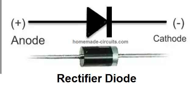
The main properties of a rectifier diode are as follows:
- A diode has two terminals namely anode and cathode.
- In a rectifier diode, the cathode side terminal is marked with a while band,
- In a rectifier diode, current can flow only in one direction, that is from anode, towards cathode. Current cannot flow the opposite.
- It means, the diode will conduct only when a positive DC is connected to the anode, and negative DC is applied to the cathode. If this polarity is reversed, the diode will not conduct, and will block the current.
- Due to this property, rectifier diodes are normally used for rectification of AC to DC. Meaning, when an alternating current is applied to the anode of the diode, it allows only the positive half cycles to pass to the cathode side and blocks the negative cycle, and in this way the AC is rectified to DC by the diode.
- A rectifier diode being a semiconductor device, will always create a drop of around 0.6 V across its anode and cathode terminals. Meaning, when a voltage is applied at anode, the cathode will produce a voltage which may be 0.6 V less than the voltage applied at the anode.
Applications Circuits
As explained in the above sections, a diode is an indispensable component without which it is virtually impossible to build an electronic circuit.
Although, in majority of the circuits a diode plays a less important role, there are many applications where diodes work as the crucial component, and we are going to discuss a few of these applications circuits using diodes, in the following paragraphs.
Half Wave and Full Wave Rectifiers
One of the main applications of diodes is in power supplies. An AC to DC power supply can be made either by using a basic single diode to form a half wave AC to DC power supply or, by using 4 diodes in a bridge network configuration to create a full wave AC to DC power supply circuit. The two variants can be seen in the following diagrams,
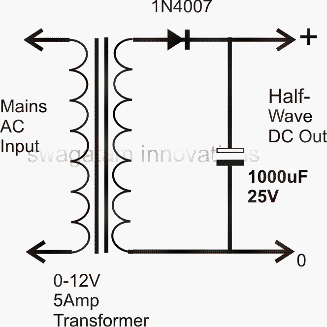
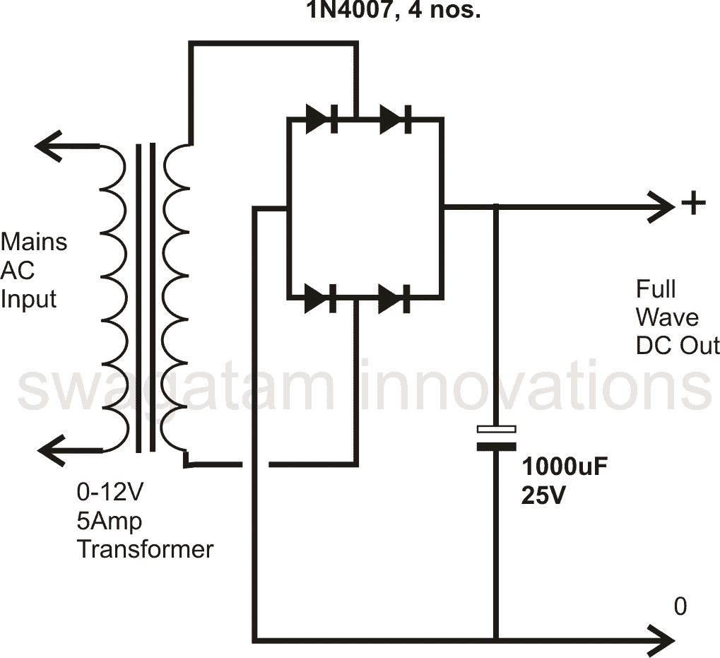
Out of the two power supply applications of the diode, the full wave version is the more efficient one since it converts both the cycles of the AC into DC, while the single diode version converts only the half AC waves into DC.
The bridge rectifier connected with a transformer and without a filter capacitor can also be used as a stable 100 Hz frequency source or a 100 Hz frequency oscillator.
110 VAC to 220 V DC Converter
This converter can be very handy for operating 220V equipment from 110V sources. The two diodes along with the two high voltage capacitors are configured as voltage doubler, which quickly converts the 110V into a 220V DC output.
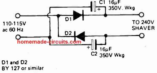
However, since the output is a DC, this can be diode application circuit can be used only for appliances that can work with AC and DC both, for example, electric shavers, LED lamps, heaters, electric motors, electric iron, soldering iron etc.
Air Ionizer
The above voltage doubler when extended to many more stages using diodes and capacitors, to form a ladder, it ultimately constitutes a very special device called the air ionizer circuit.
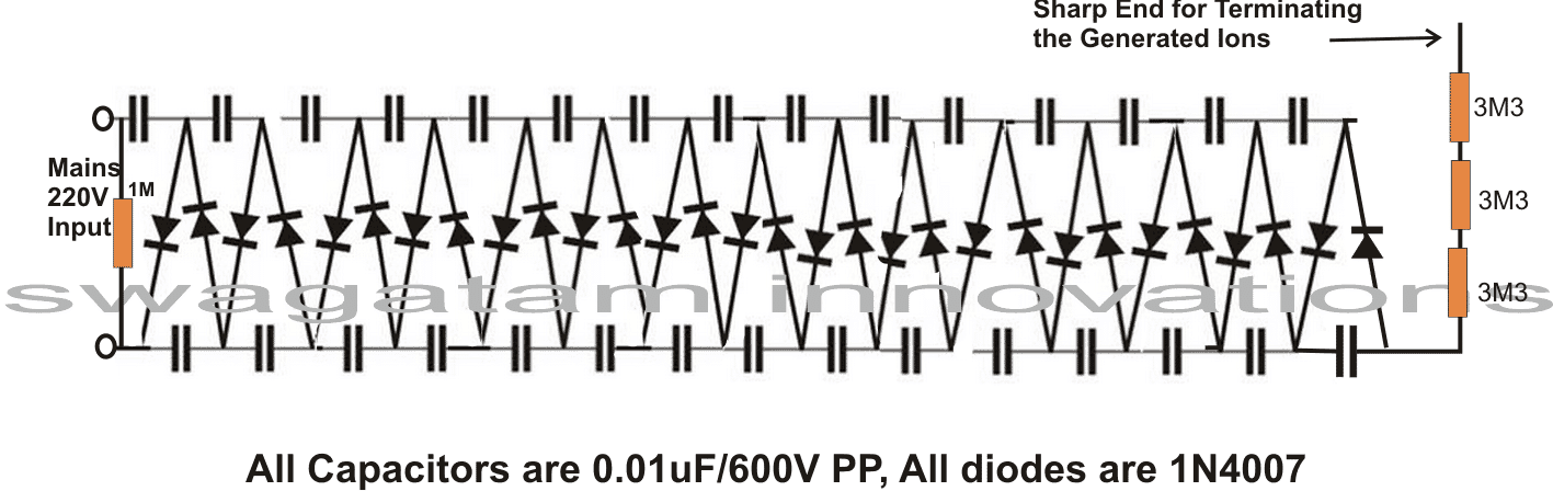
This configuration mainly uses the rectification and blocking feature of the diode, and the charge multiplying feature of the capacitors, to form a high negative voltage generator circuit which can be used for purifying the air around you!
For Voltage Dropping
As discussed in the previous sections, a rectifier diode will drop around 0.6V when a voltage is passed through it. This feature can be used for deriving lower amounts of voltage from higher sources.
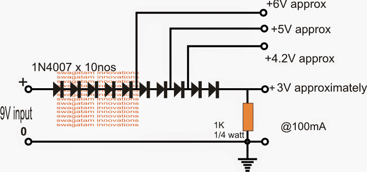
For example, if a 3.3 V is required from a 5 V source this can be easily achieved by adding a few series rectifier diodes at the output of the 5 V source. Since each diode drops around 0. 6 V, it means 2 nos of diodes would be just enough for getting the required 3.3 V from a 5V supply.
Solar Battery charger
The above voltage dropping feature of a rectifier diode can be applied for making a simplest type of solar battery charger as shown below:
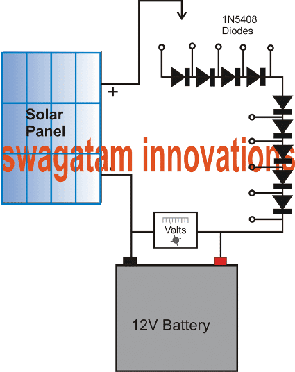
Here we can see, many diodes are used in series to control the output from a solar panel to match the battery charging voltage. The diodes drop the solar panel voltage in steps so that the voltage levels can be selected from low to high, as the sunlight goes down, thus making sure that the higher panel specifications does not cause any problems, and it is made compatible with any desired battery simply by switching a handful of rectifier diodes in series.



Questions & Answers
Hello dear Swagatam
I did your Air purifier circuit and it works well. Thank you for that. Since I have plenty of 0.47 Mf 630 V non polar capacitor and 1N5404 diodes as well, can I use them to build another more power air purifier? If yes, am I obliged to use 1N5404 or those 1N4007 diodes would be good and What about wattage of resistors if your answer would be yes.
Thank you very much for your reply
Wish you all the best dear man
Thank you Ali, glad the circuit is working well. You can use 0.47uF/630V, but you cannot use 1N5404, since its RMS is arted at only 280V….you can either use a 1N4007 or 1N5408. Resistor wattage will remain the same!
Hello Dear Swagatam,
I made and use already a simple Mains Power Failure detector. This is helpful to track and trace when failures happens as the circuit is connected to Velleman Interface Board 8055.
Now I struggle to build a circuit to detect when the mains is back. i.e. Measure just one time, let say for a small periode of 5 seconds this event. Any suggestion ?
Hello Foxytron, do you mean the LED should be turn ON for 5 seconds each time mains AC comes back?
Hi Swagatam,
A LED that turns on for a couple of seconds could be an option. But when the mains comes back, the LED must turns ON only one time for e.g. 5 Sec and than shut off.
Thanks
Thanks Foxytron, However switching the LED ON only one time appears difficult, I can’t figure it out right now.
Thanks Swagatam,
It is a challenge for me too. I’ll share to you If a solution pops up.
Thanks for anyway.
You are welcome Foxytron. All the best you!