In this post I have explained how to design and build a simple power supply circuit right from the basic design to the reasonably sophisticated power supply having extended features.
Power Supply is Indispensable
Whether it's an electronic noob or an expert engineer, all require this indispensable piece of equipment called the power supply unit.
This is because no electronics can run without power, to be precise a low voltage DC power, and a power supply unit is a device which is specifically meant for fulfilling this purpose.
If this equipment is so important, it becomes imperative for all in the field to learn all the nitty-gritties of this important member of the electronic family.
Let's begin and learn how to design a power supply circuit, a simplest one first , probably for the noobs who would find this information extremely useful.
A basic power supply circuit will fundamentally require three main components for providing the intended results.
A transformer, a diode and a capacitor.The transformer is the device which has two sets of windings, one primary and the other one is the secondary.
Mains 220v or 120v is fed to the primary winding which is transferred to the secondary winding to produce a lower induced voltage there.
The low stepped down voltage available at the secondary of the transformer is used for the intended application in electronic circuits, however before this secondary voltage can be used, it needs to be first rectified, meaning the voltage needs to be made into a DC first.
For example if the transfornmer secondary is rated at 12 volts then the acquired 12 volts from the transformer secondary will be a 12 volt AC acros the relevant wires.
Electronic circuit can never work with ACs and therefore this voltage should be transformed into a DC.
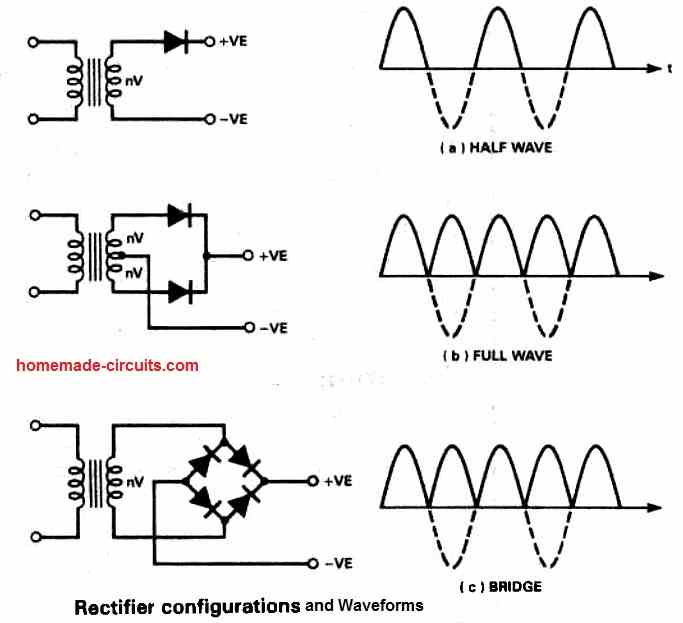
A diode is one device which effectively converts an AC to DC, there are three configurations through which basic power supply designs may be configured.
You may also want to learn how to design a bench power supply
Using a single diode:
The most basic and crude form of power supply design is the one which uses a single diode and a capacitor.
Since a single diode will rectify only one half cycle of the AC signal, this type of configuration requires a large output filter capacitor for compensating the above limitation.
A filter capacitor makes sure that after rectification, at the falling or decreasing sections of the resultant DC pattern, where the voltage tends to dip, these sections are filled and topped by the stored energy inside the capacitor.
The above compensation act done by the capacitors stored energy helps to maintain a clean and ripple free DC output which wouldn't be possible just by the diodes alone.
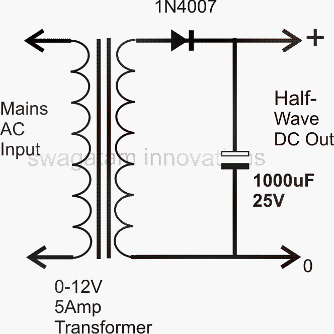
For a single diode power supply design, the transformer's secondary winding just needs to have a single winding with two ends.
However the above configuration cannot be considered an efficient power supply design due to its crude half wave rectification and limited output conditioning capabilities.
Using Two Diodes:
Using a couple of diodes for making a power supply requires a transformer having a center tapped secondary winding. The diagram shows how the diodes are connected to the transformer.
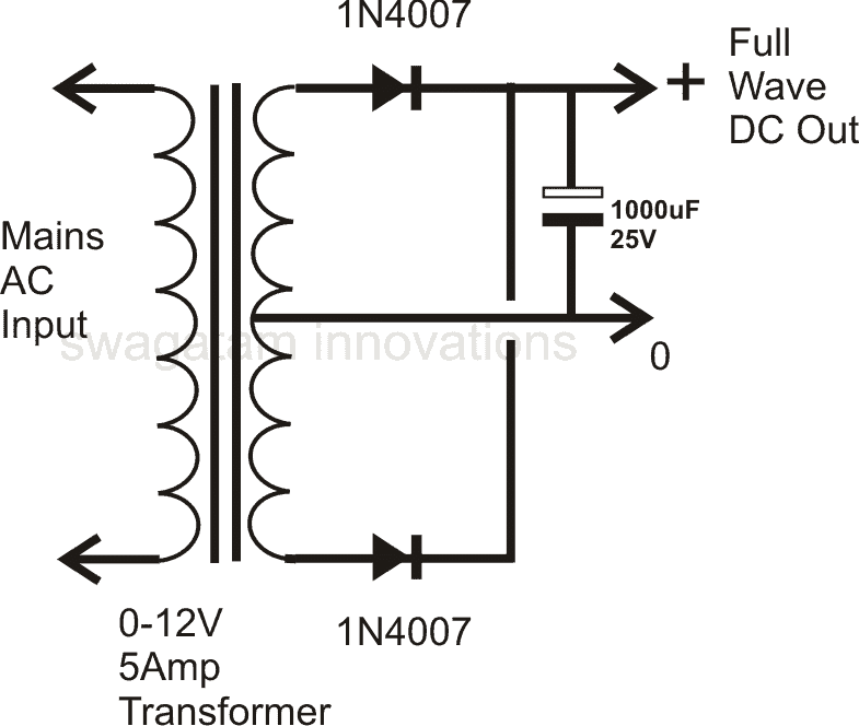
Though, the two diodes work in tandem and tackle both the halves of the AC signal and produce a full wave rectification, the employed method is not efficient, because at any instant only one half winding of the transformer is utilized.
This results in poor core saturation and unnecessary heating of the transformer, making this type of power supply configuration less efficient and an ordinary design.
Using Four Diodes:
It's the best and universally accepted form of power supply configuration as far as the rectification process is concerned.
The clever use of four diodes makes things very simple, only a single secondary winding is all that is required, the core saturation is perfectly optimized resulting in an efficient AC to DC conversion.
The figure shows how a full wave rectified power supply is made using four diodes and a relatively low value filter capacitor.
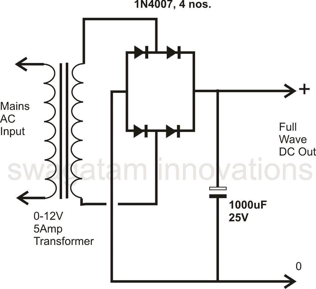
This type of diode configuration is popularly know as the bridge network, you may want to know how to construct a bridge rectifier.
All the above power supply designs provide outputs with ordinary regulation and therefore cannot be considered perfect, these fail to provide ideal DC outputs, and therefore are not desirable for many sophisticated electronic circuits.
Moreover these configurations does not include a variable voltage and current control features.
However the above features may be simply integrated to the above designs, rather with the last full wave power supply configuration through the introduction of a single IC and a few other passive components.
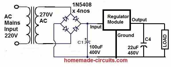
Full Bridge Unregulated Power Supply with Formulas
The diagram below depicts a single rail power supply. The fuse is installed in the live wire path to the transformer for safety.
The live wire is also attached to the transformer's 240V terminal; this section of the primary winding is quite far away from the secondary, increasing the unit's safety.
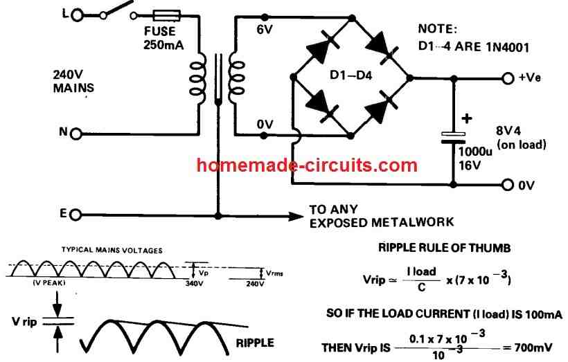
The earth should be linked to any uncovered metal and, if applicable, to the transformer shielding. The voltages mentioned are in volts rms and are AC voltages.
On load, the transformer's output is 6V rms. When the transformer is not in use, the voltage might rise by up to 25%.
The output ripple can be calculated using the following formula:
Vrip ≅ Iload / C [ 7 x 10⁻³ ]
Waveform Images
The output waveform images for the various rectifiers and transformer configurations discussed above, can be seen in the figure below:
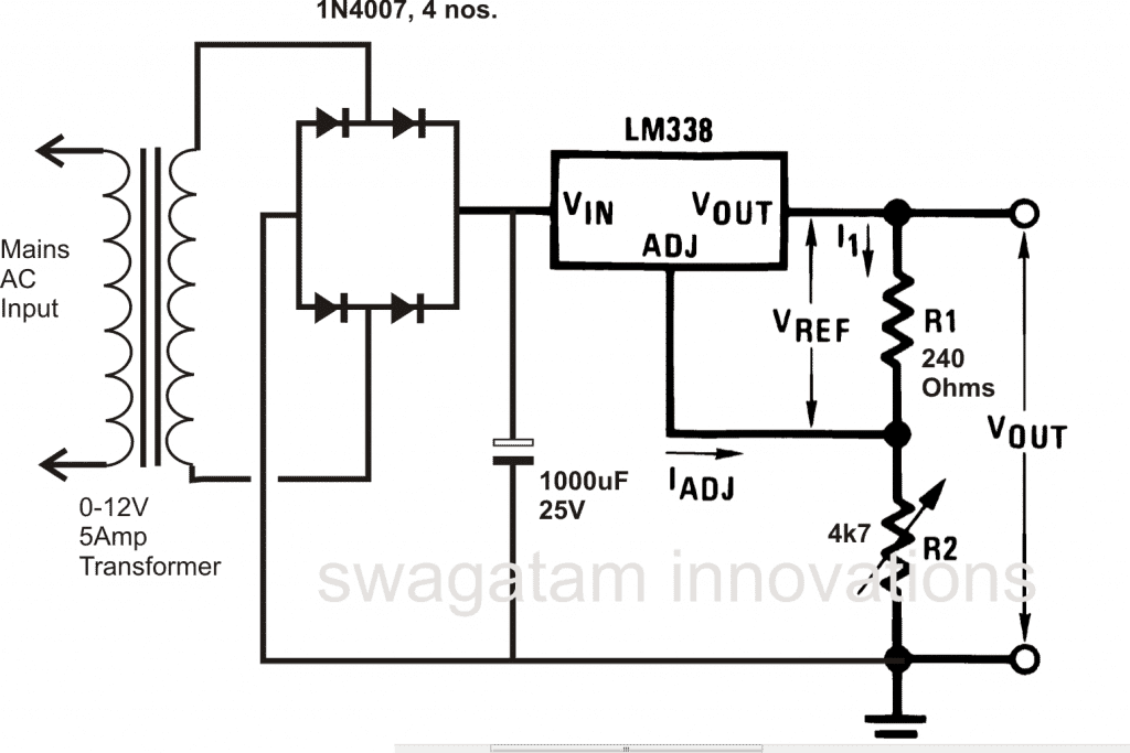
Using the IC LM317 or LM338:
The IC LM 317 is a highly versatile device which is normally incorporated with power supplies for obtaining well regulated and variable voltage/current outputs. A few power supply example circuits using this IC
Since the above IC can only support a maximum of 1.5 amps, for greater current outputs another similar device but with higher ratings may be used. The IC LM 338 works exactly like the LM 317 but is capable of handling up to 5 amps of current. A simple design is shown below.
For obtaining fixed voltage levels, 78XX series ICs may be employed with the above explained power supply circuits. The 78XX ICs are comprehensively explained for your refernce
Nowadays transformerless SMPS power supplies are becoming the favorites among the users, due to their high efficiency, high power delivering features at amazingly compact sizes.
Though building an SMPS power supply circuit at home is surely not for the novices in the field, engineers and enthusiasts with comprehensive knowledge about the subject can go about building such circuits at home.
You can also learn about a neat little switch mode power supply design.
There are a few other forms of power supplies which can be rather built by even the new electronic hobbyists and does not require transformers.
Though very cheap and easy to build, these types of power supply circuits cannot support heavy current and are normally limited to 200 mA or so.
Transformerless Power Supply Design
Two concepts of the above transformer less type of power supply circuits are discussed in the following couple of posts:
By Using High Voltage Capacitors,
Feedback from One of the Dedicated Readers of this Blog
Dear Swagatam Majumdar,
I wish to make a psu for a micro-controller and its dependent components...
I want to get a stable +5V out and +3.3V out from the psu, I'm not sure of the amp-age but I think a 5A total should be enough, there will also be 5V Mouse and 5V Keyboard and 3 x SN74HC595 IC's too and 2 x 512Kb SRAM ... So I really dont know the amp-age to aim for....
I guess 5Amp is enough?.... My MAIN question is which TRANSFORMER to use and which DIODES to use? I have chosen The transformer after reading somewhere online that the bridge rectifier cause a VOLT DROP of 1.4V in general and in your blog above you state the bridge recitfier will cause the voltage to go up?...
SO I am unsure (I am unsure anyway being new to electronics) ..... The FIRST transformer I chose was this one. Please advise me which one is BEST for my needs and which DIODES to use too.... I would like to use the PSU for a board very similar to this....
Please help and guide me the best way to make a suitable MAINS 220/240V PSU which gives me STABLE 5V and 3.3V for use with my design. Thank You In Advance.
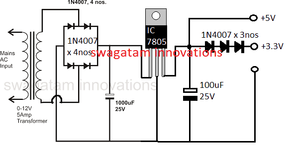
How to Get Constant 5V, and 3V from Power Supply Circuit
Hello, you can achieve that simply through a 7805 IC for getting the 5V and by adding a couple 1N4007 diodes to this 5V for getting approximately 3.3V.
5 amp looks too high and I don't think you would require this much high current unless you are also using this supply with an external driver stage carrying higher loads such as a high watt LED or a motor etc.
So I am sure that your requirement can be easily fulfilled through the above mentioned procedures.
for powering MCU through the above procedure you can use a 0-9V or a 0-12V trafo with 1amp current, diodes could be 1N4007 x 4nos
The diodes will drop 1.4V when the input is a DC but when it's an AC like from a trafo then the output will be raised by a factor of 1.21.
make sure to use a 2200uF / 25V cap after the bridge for the filtration
I hope the info will enlighten you and answer your queries.
The image above shows how to get 5V and 3.3V constant from a given power supply circuit.
How to Get 9 V Variable Voltage from IC 7805
Normally, the IC 7805 is considered as a fixed 5 V voltage regulator device. However, with a basic workaround, the IC could be turned into a 5 V to 9 V variable regulator circuit, as shown above.
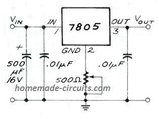
Here, we can see that a 500 ohm preset is added with the central ground pin of the IC, which allows the IC to produce a lifted output value up to 9 V, with a current of 850 mA. The preset could be adjusted o get outputs in the range of 5 V to 9 V.
For getting an increased voltage output from a 7812 IC, you can refer to this post!
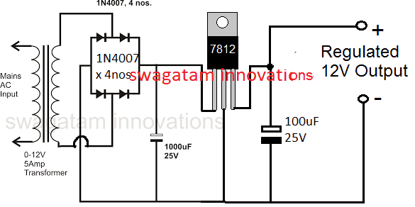
Making a Fixed 12V Regulator Circuit
In the above diagram we can see how an ordinary 7805 regulator IC could be used for creating a fixed 5V regulated output.
In case you wanted to achieve a fixed 12V regulated power supply, the same configuration could be applied for getting the required results, as shown below:
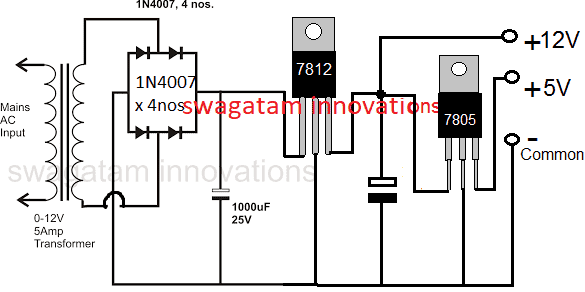
12V, 5V Regulated Power supply
Now suppose you had circuit applications which needed a dual supply in the range of 12V fixed and also 5V fixed regulated supplies.
For such applications the above discussed design could be simply modified by using a 7812 IC and then subsequently a 7805 IC for getting the required 12V and 5V regulated power supply output together, as indicated below:
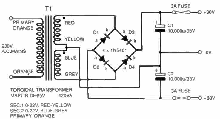
Designing a Simple Dual Power Supply
In many of the circuit applications, especially the ones using op amps, a dual power supply becomes mandatory for enabling the +/- and ground supplies to the circuit.
Designing a simple dual power supply actually involves a just a center tap power supply and a bridge rectifier along with a couple of high value filter capacitors as shown below:
However, for achieving a regulated dual power supply with the desired level of dual voltage at the output is something which normally requires a complex design using costly ICs.
The following design shows how simply and discretely a dual power supply could be configured using a few BJTs, and a few resistors.
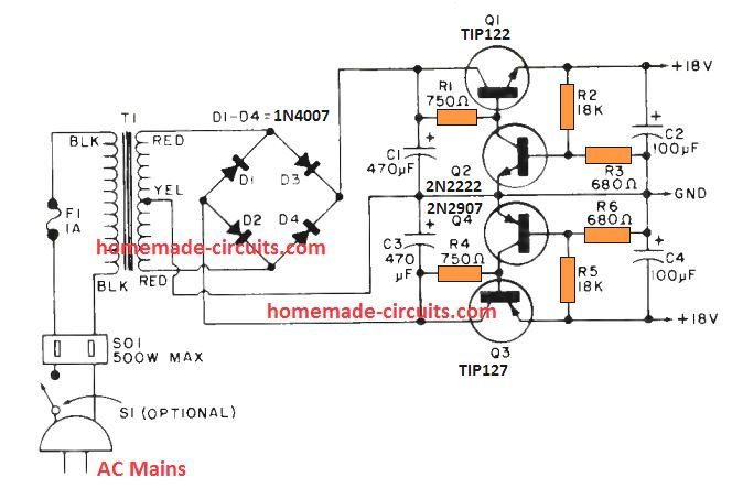
Here Q1 and Q3 are rigged as emitter follower pass transistors, which decide the amount of current that is allowed to pass across the respective +/- outputs. Here, it is around 2 amps
The output voltage across the relevant dual supply rails is determined by the transistors Q2 and Q4 along with their base resistive divider network.
The output voltage levels could be appropriately adjusted and tweaked by adjusting the values of the potential dividers formed by the resistors R2, R3 and R5, R6.
Dual Supply with a Single Opamp
If you an extra opamp left in your circuit that demands a dual supply from a single supply, then perhaps the following simple dual power supply from a single opamp configuration can be tried.
The resistors R1 and R2 work like a high impedance, and consequently economical voltage divider network. The opamp ensures that the artificial ground potential is always identical to the potential bteween the junction of R1 and R2.
The connection between R1 and R2 establishes the relationship between the a couple of output voltages; if R1 and R2 possess the identical value, exactly the same will be ensured for both the output voltages which would be perfectly symmetrical.
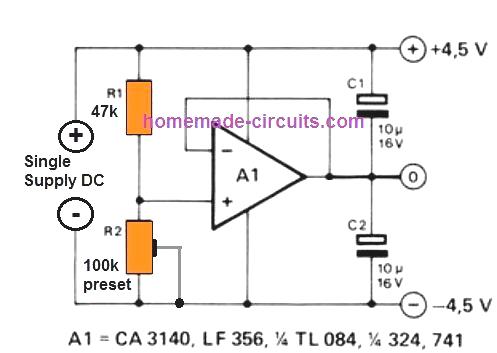
This allows us to get the most desirable feature of the circuit, it is that the R1/R2 partnership doesn't rely on the battery voltage!
An additional benefit of this active potential divider is that (as opposed to a basic resistor divider chain) it adjusts itself nicely to varying load currents moving to and from the earth supply line, especially with regards to unsymmetrical load current situations.
You can probably think of using different variants of opamps for this circuit.
The 3140 and 324 tend to be fantastic choices, despite having a battery voltage as low as 4.5 V.
Keep in mind that the highest voltage that can be tolerated by these ICs is not more than 30 V, and the maximum load current that can be tolerated by the opamp will also depend on the type of the opamp.
Designing an LM317 Power Supply with Fixed Resistors
An extremely straightforward LM317T-based voltage/ current supply, that could be employed for charging Nickel-Cadmium cells or any time a practical power supply is necessary, is demonstrated below.
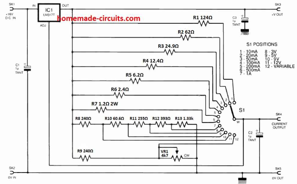
It is an uncomplicated venture for the newbie to construct, and is meant to be utilized with a plug-in mains adaptor providing an unregulated d.c. output. IC1 is actually a adjustable regulator type LM317T.
The rotary switch S1 chooses the setting (constant current or constant voltage) along with the current or voltage value. The regulated voltage can be obtained at SK3 and the current is in SK4.
Observe that a adjustable setting (position 12) is incorporated that enables a variable voltage to be tailored through potentiometer VR1.
The resistor values must be manufactured from the closest obtainable fixed values, positioned in series as necessary.
Resistor R6 is rated at 1W and R7 at 2W although the remaining could be 0.25W. Voltage regulator IC1 317 must he installed to some heatsink the size of which is determined by the input and output voltages and currents necessary.
Getting 5 Amps from a 7812 IC
If you are wondering how to get 5 amp or higher current from a 7812 regulator IC, then the following circuit might be the one you are looking for.
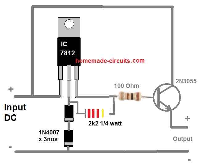
As you can see a power transistor 2N3055 is configured with the 7812 output as an emitter follower for transforming the 1 amp current from the 7812 output into a massive 5 amp current at the emitter of the transistor.
However, there's a drawback of using an emitter follower configuration. It reduces the output voltage by 0.7 V or 1 V due to the base-emitter forward voltage drop specification of the BJT.
To compensate this we raise the 7812 output by around 1 V by adding a couple of series diodes at the GND terminal of the IC.
The 100 ohm resistor at the base of the transistor determines the output current. The 100 ohm value is arbitrarily chosen.
If you find 100 ohms not delivering the intended 5 amps then you can try reducing this value. Just make sure the wattage of the resistor is also appropriately increased so that the resistor does not heat up and burn.
Designing a Basic 741 based Regulator Circuit
Presented below is an exclusive depiction of a dual-stage voltage regulator setup, proficient in delivering approximately 3 Amps at its output.
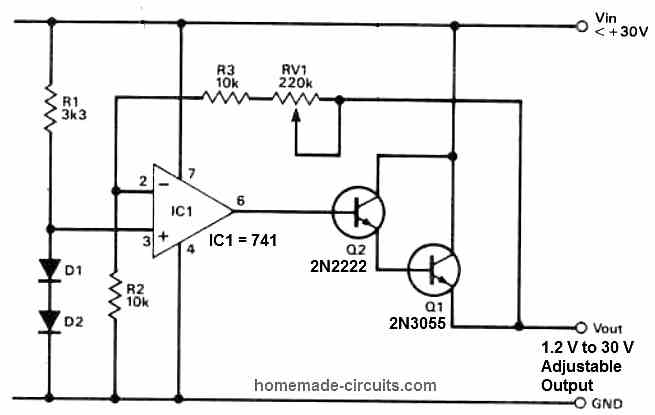
The primary stage incorporates an op-amp IC 741, functioning as a DC voltage amplifier.
An adjustable amplification factor allows a wide array of output voltage options, achieved by employing a reference voltage derived from a stack of diodes as the input signal.
The subsequent stage serves as a current amplifier, efficiently converting the available 10 mA from the op-amp output into a usable 3 A supply current.
Using a Feedback
An intriguing aspect of this configuration is that the current gain stage is integrated into the feedback loop of the system.
Consequently, the regulator's output voltage is determined by the product of the reference voltage and the op-amp gain, where the op-amp gain is calculated from the expression:
A: (Rf + Rin)/Rin.
To obtain this gain value, a potential divider is formed using the total value of the feedback resistors Rf and the input resistor Rin.
This well-engineered setup ensures optimal voltage regulation with high precision, catering to a variety of practical applications.

Questions & Answers
I just love about circuits to their functions/ characteristics. Can you please help me to Design a circuit that 220V AC to 2.4V DC output with 2.5A.
Thank you sukumar,
A 220V to 2.4V DC 2..5 amp power supply can be built either using a transformer based design or an SMPS based design, there are no other easy options unfortunately.
Using a transformer can be bulky and heavy, and SMPS can be complex to build for a newcomer.
Let me know which design do you prefer.
Hi swagatam, firstofall thankyou very much for your kind attention to my request. As per your point of view referring, I’d like to build a circuit which is easy & less cost.
You are welcome sukumar,
In that case you can use a 6V 1 amp transformer, then use a bridge rectifier and a filter capacitor to make the 6V AC into 8.5V DC output. Then use a XL4015 based buck converter to convert this 8.5V DC into the required 2.4V 2.5 amps DC.
Let me know if you have any further doubts.
Hi George, are you trying to figure out the primary and secondary sides of the transformer?
Hi Swagatam hope you are well. Yes the primary side is the bottom of the pic that i get but its the secondary side that is giving me problems not sure how to test.
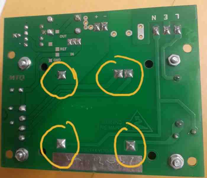
What sort of problem are you facing? I would rather recommend removing the trafo from the PCB and then confirming the voltage levels, and the issues if any.
Thank you I will gave it go.
Sure, no problem…
Sir,
I need help for my 3D printer power supply, it’s 24 volt 240 watt but it’s giving only 12 volt, I have replaced the transistors and feedback ic but still 12 volt output, the local supply don’t work. Original is too expensive.
Hi Ajay, did you check the output by removing or disconnecting the feedback link entirely?
Hi Swagatam, I am failing at finding a simple circuit to invert a +5v to -5V from a usb source.
I have some encoders that are 2 channel A+ and B+ but apparently the driver board requires a A- and B- as well so I figured I could just invert the pulse from both channels but I’m not smart enough to locate a circuit to accomplish this that is not huge and far to cumbersome.
Hi Shawn,
Yes, I find it difficult too..
An easy method is shown in the following article. Please see the first diagram on top.
However, for this you will have to buy the IC LM2664.
https://www.ti.com/lit/ds/symlink/lm2664.pdf?ts=1711337251116&ref_url=https%253A%252F%252Fwww.google.com%252F
Thank you so much for the quick reply!
My pleasure!
Hi again Swagatam, I’ve really been struggling with this. I’m trying to invert a pulse signal from an encoder and I finally got the circuit functional but the driver board errors out after about a revolution of the encoder. I think the cap is not discharging fast enough and is too large. I went all the way down to .1uf poly (the green ones) and have ordered ceramic at 10,100pf and .1 and 3,3uf as I am guessing that i don’t want a high value and a quick discharge. But I am wondering if maybe I should be using a discharge resistor and if so what value or if I am totally off track here? Thanks in advance for any help. BTW I soldered the SOT-23 (6) package directly (NIGHTMARE TERRITORY!) and the first 3 broke the legs while i tried to connect leads lol I cant believe they only sell them in that micro package! I ended up getting breakout boards and boy did that make my life easier! 😀 Oh and I eliminated the output cap as It was not discharging fast enough and I think its not really needed in this application.
Thanks for the update Shawn,
I guess you are referring to the circuit from the following datasheet:
https://www.ti.com/lit/ds/symlink/lm2664.pdf?ts=1711337251116&ref_url=https%253A%252F%252Fwww.google.com%252F
Here, C1 and C2 are supposed to be 3.3uF, low ESR capacitors. I would recommend using tantalum capacitors for these caps.
I am not actually sure about the significance of output capacitor C2.
If you think C2 is causing the problem due to slow discharging, you can try adding a resistor parallel to C2 as shown on page 7 of the datasheet.
I can see a formula given to calculate the resistor Rout, but it looks too daunting.
So i would recommend you to try the Rout resistor value with some trial and error. You can start with a 1k resistor first and see how it goes.
However, if eliminating C2 still works for you, then i think there’s nothing more we can do, because the other cap C1 is crucial and cannot be removed and it cannot be modified with any external components either.
Let me know if you have any further doubts.
Can’t edit last post, I’m trying to get tanalums I can’t find esr values! I have been looking t data sheets but they don’t list them and using the simsurfing tool is not showing them either. I think I’ve fallen down the rabbit hole. 🙂
The quickest I cant get them shipped looks like walmart in 3 days but i don’t know what ones to order. I orginally order ceramic because I gave up trying to find esr values and read somewhere ceramic had the lowest.
Ceramic may have the lowest esr, you are right. I suggested tantalums since the diagram showed polarized capacitors, however there’s no need of using polarized caps, so even ceramic caps can be used…
Thx, I’m going to try the ceramics when they come in as the datasheet notes “Capacitors with higher ESR will increase output resistance, reduce output voltage and efficiency” which is really fine by me as its only a reference point for a differential circuit. If the ceramics don’t work then I will look for tantalum with a quick discharge rate. I’ll update again when they show up. I was looking up discharge rate and from the formula it looks like the lowest esr value will discharge the quickest, do I understand that correctly? It seems to make since that the lower the resistance the quicker it would discharge.also the 3.3 value I think is for a continuous supply and I could not get a trailing edge so I tried various resistors on cap 2 to no avail and then removed c2 to some success and then lowered the value to 2.2 and then .1 and then the trailing edge was more defined and I think the driver board needs that or it will detect the differential as being an error if the values fall out of tolerance. that is my guess as I have no clue how that circuit functions, it is a black box.
You are right, A capacitor with a lower ESR (Equivalent Series Resistance) will discharge quicker than one with a higher ESR.
If your current modifications are working for you then you can continue with them.
Let us know how it goes.
Thank you for the information you’ve provided. I already have a Altech corp. dr-120-24 power supply. I want to take the existing output of 24v 5a and split it into two 9v 2.5a circuits. I’ve been reading online and watching lectures and believe knocking the voltage down to 9v then splitting the 5a between two circuits should be pretty straight forward but can’t seem to find a solution. *or* more likely I’m just missing what they are already explaining to me. Would this be a simple circuit to design or is it a complex design. Thank you in advance for your time.
Hi, thanks for the question.
I don’t think it is possible to split current. Current can be limited or restricted and controlled, it cannot be divided. Voltage can be split, and the current through each channel could be limited to 2.5 amps.
Is it true if a device requires 2.5a it doesn’t have a negative impact, if the circuit has 5a available? My latest understanding is if the circuit has equal to or greater than the current required all is good. Of course the voltages need to match.
If I can create two circuits at 9v then i should not care if 5a available on both circuits. Each circuit or branch will have a end device which requires 9v 2.5a. so two 9v 5a branches should work? Or is this grossly frowned upon?
Hope this gets closer to filling in the variables for you.
-Daniel
Yes, that’s right, if the voltage specifications is matched as per the load specifications the current becomes immaterial, it can be of any level, doesn’t matter. If you are supplying two separate 9V 5A sources to your 9V/2.5 amps devices then it is perfectly fine.
Well done Swagatam. Mine is, how do I register in your tutorial lesson for more knowledge. I am interested in knowing electronic configuration, design and troubleshooting. I want a full lesson from you. How do I go about that with you pls?
Thank you Femi, learning electronics can be a long process involving a lot of theoretical and practical courses. You can start by building transistor based circuits, and learn how the configurations are designed to work. If you have any issues you can ask your questions under any relevant article here, I will try to sort them out for you.
The design diagram and the outlines must be in a simple way so that any hobbiest having not enough practice must follow easily so that his thrust of gaining and seeking knowledge about the goining on SMPS be satisfied and enjoybl…….
..
You can always feel free to ask through comments if you you have any doubts, I’ll be most happy to help!
Really what I need is to remove a relay switch on my circuit, I have a relay for cut-off when the battery gets to full charge and a relay for transition when the main supply is off, I want to remove the relay for cut-off.
Without a relay how will you implement the cut off action?
I want to use a 14V zener diode to simply clamp the circuit sir.
Where do you want to connect the zener diode?
I sent you the link to the schematic sir did you see it?. but effectively that is exactly the help I need from you, where can I connect the zener to simplify the circuit cause really I just want to simplify it.
Jack, external website links cannot be published. If possible I will extract the circuit diagram from your link and post it here to continue the discussion…but it might take some time for that. I will let you know once it is done.
alright sir thank you.
Can you please tell me what change exactly do you want in the following circuit, or simply tell me your requirements, I will give a new circuit:
I want to use a zener to protect the battery from overcharge, I also want to use only one relay for transition. I also want to protect the battery from over discharge. Can you help with that sir?
OK, I think you can try the last diagram from the following article. The MOSFET can be replaced with any PNP power transistor.
https://www.homemade-circuits.com/battery-deep-discharge-protection-circuit/
Thank you very much sir.
You are welcome Jack!
Hello Sir. I hope you are well. I need your help with a schematic, it’s a 12V power supply with a back up battery I have the schematic how can I send it to you for help.
Hello Jack,
You can upload the link to any free online image hosting site and provide me the link here…I will check it out.
Bro can you kindly help me to build a 0-30v and 0-20a variable SMPS?
I have already made an linear power supply from your suggestions but I heard that SMPS has greater efficiency to willing to make one too.
So please help to build a complete variable SMPS from scrap
Sorry Bivash, I do not have a 30 V, 20 amp SMPS circuit with me. I will try to look for it, if I find, i will let you know.
Ok bro
I love this, it definitely helps me in my projects. Thank you sir and keep up the good work ????
You are welcome Victor!
Hello sir, how can I make a full wave rectifier with a 12 and 24 Voltsdesired output DC from 12 and 24 AC. Can you help me in designing it.
Hello Khina, I am sure you know how to make a bridge rectifier using rectifier diodes. If not then you can refer to the following article. You can make two of these bridge rectifiers, and connect one bridge across the 12 V wires and connect the second bridge across the 24 V wires. This configuration will be enough to convert the AC voltage into unfiltered DC outputs.
https://www.homemade-circuits.com/how-to-understand-diodes-and-build/