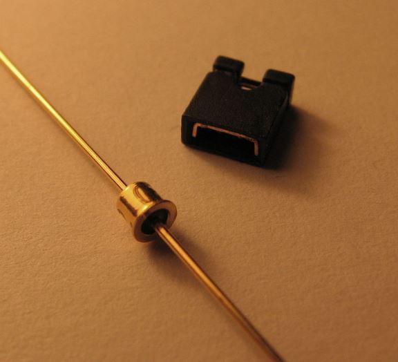
A tunnel diode is a type of semiconductor diode which features a negative resistance on account of a quantum mechanical effect known as tunneling.
In this post I have explained the basic characteristics and working of tunnel diodes, and also a simple application circuit using this device.
We will see how a tunnel diode could be used for changing heat into electricity, and for charging a small battery.
Overview
After a long disappearance from the semiconductor world, the tunnel diode, has been actually re-launched as a result of the fact that it could be implemented to convert heat energy into electricity. Tunnel diodes are also known as Esaki diode, named after its Japanese inventor.
In the nineteen fifties and sixties, tunnel diodes were implemented in a lot of applications primarily in RF circuits, in which their extraordinary qualities were taken advantage of for producing extremely fast level sensors, oscillators, mixers, and stuff like that.
How Tunnel Diode Works
In contrast to a standard diode, a tunnel diode works by using a semiconductor substance that has an incredibly large doping level, leading to the depletion layer between the p -n junction to become approximately 1000 times narrower even than the fastest silicon diodes.
Once the tunnel diode is forward biased, a process known as "tunnelling" of the electron flow starts happening throughout the p -n junction.
"Tunnelling" in doped semiconductors is actually a method not easily understandable using conventional atomic hypothesis, and cannot perhaps be covered in this small article.
Relationship between Tunnel Diode Forward Voltage and Current
While testing the relationship between a tunnel diode's forward voltage, UF, and current, IF, we can find that the unit owns a negative resistance characteristic between the peak voltage, Up, and the valley voltage, Uv, as demonstrated in Fig below.
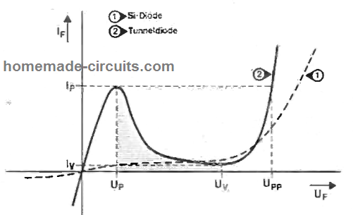
Therefore, when the diode is powered within the shaded area of its IF-UF curve, the forward current comes down as the voltage goes up. The resistance of the diode is without any doubts negative, and normally presented as -Rd.
The design I have I have explained in this article takes the advantage of the above quality of tunnel diodes by implementing a set of serially connected tunnel diode devices to charge a battery through solar heat (not solar panel).
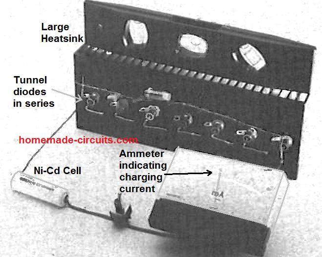
As observed in Figure below, seven or more Gallium-Indium Antimonide (GISp) tunnel diodes are hooked up in series and clamped over on a big heatsink, which helps prevent dissipation of their power (tunnel diodes get cooler as UF goes higher or increased).
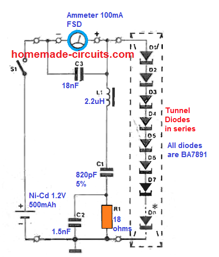
Heatsink is used to enable an effective accumulation of solar heat, or any other form of heat that may be applied, whose energy is required to be transformed into a charge current for charging the proposed Ni-Cd battery.
Convert Heat to Electricity using Tunnel Diodes (Thermal Electricity)
The working theory of this special configuration is actually amazingly straightforward. Imagine an ordinary, natural, resistance, R, is able to discharge a battery through a current I=V/R. which implies that a negative resistance will be able to initiate a charging process for the same battery, simply because the sign of I gets reversed, that is: -I=V/-R.
In the same way, if a normal resistance allows heat dissipation by P= PR watts, a negative resistance will be able to provide the same amount of wattage into the load: P = -It-R.
Whenever the load is a voltage source on its own with relatively reduced internal resistance, the negative resistance have to, certainly, generate a greater level of voltage for the charge current, Ic, to flow which is given by the formula:
Ic= δ[ Σ(Uf) - Ubat] / Σ (Rd)+Rbat
Referring to the annotation Σ (Rd) it is right away understood that all diodes within the string sequence have to be run inside the -Rd region, mainly because any individual diode with a +Rd characteristic might terminate the objective.
Testing Tunnel Diodes
To make certain that all of diodes present a negative resistance, a straightforward test circuit could be designed as revealed in the following figure.
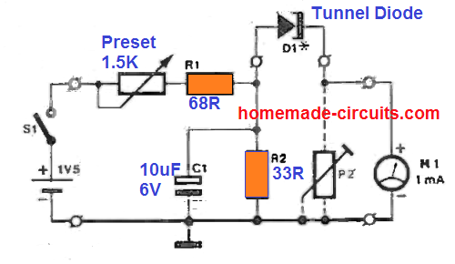
Observe that the meter should be specified to indicate the polarity of the current, because it could very well happen that a specific diode has a really excessive IP:Iv ratio (tunnel slope) causing the battery to unexpectedly charged on implementing a small forward bias.
The analysis has to be performed at an atmospheric temperature below 7°C (try a cleaned out freezer), and note down the UF-IF curve for every single diode by meticulously increasing the forward bias through the potentiometer, and documenting the resulting magnitudes of IF, as displayed on the meter reading.
Next, bring an FM radio close by to make certain that the diode which are being tested are not oscillating at 94.67284 MHz (Freq , for GISp at doping level 10-7).
If you find this happening , the specific diode may be unsuitable for the present application. Determine the range of OF that guarantees -Rd for just about all diodes. Based on the manufacturing threshold of the diodes in the available lot, this range could be as minimal as, say, 180 to 230 mV.
Application circuit
The electricity generated by tunnel diodes from heat can be used for charging a small Ni-Cd battery.
First determine the quantity of diodes necessary for charging the battery through its minimal current: for the above selection of UF, a minimum of Seven diodes will have to be connected in series in order to provide a charging current of approximately 45 mA when they are warmed to a temperature level of:
Γ [ -Σ (Rd)If][ δ (Rth-j) - RΘ].√(Td+Ta)°C
Or approximately 35°C when the thermal resistance of the heatsink is no more than 3.5 K/W, and when it is installed under peak sunlight (Ta 26°C). To have the maximum efficiency out of this NiCd charger, the heatsink has to be dark-colored for the best possible heat exchange to the diodes.
Additionally it must not be magnetic, considering that any kind of outside field, induced or magnetic, will cause unstable stimulation of the charge carriers within the tunnels.
This may consequently bring about the unsuspecting duct effect; electrons may likely be knocked of from the p -n junction over the substrate, and thereby build up around the diode terminals, triggering maybe hazardous voltages depending on metallic housing.
Several tunnel diodes Type BA7891NG are, regrettably, very sensitive to minutest magnetic fields, and tests have proven that these needs to be maintained horizontal with regards to the earth's surface for interdicting this.
Original Prototype Demonstrating Electricity from Solar Heat using Tunnel Diodes


Questions & Answers
You need negative absolute resistance to generate DC power, and the diode does not have this. Its V-I curve is everywhere 1st and 3rd quadrant: +V with +I or -V with -I; these yield positive absolute resistance. The “negative resistance” between Vp and Vv is only in terms of change, e.i. temporary falling conductance, a local negative trend in an always positive value. To generate DC power the curve would have to dip below the V axis: -I with +V, and this never happens.