In this post I have explained how to make simple yet fully stabilized and regulated, variable power supply circuits using the IC 741 op amp.
Three versions of the 741 power supplies are I have explained below:
- Simple Low Current Adjustable Power Supply
- Stabilized, High Current Variable Power Supply
- Stabilized, High Current Variable Power Supply, with Short Circuit protection.
Simple Variable IC 741 Power Supply
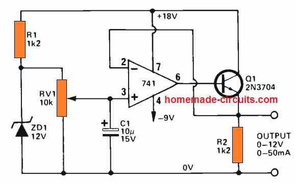
The first figure below exhibits a IC 741 based simple variable voltage power supply. This design provides a stabilized output that can be thoroughly adjusted, from 0V to 12V with current ranging up to a maximum of 50 mA.
The circuit working is very basic.
The zener diode ZD is gets the supply from the positive line through resistor R1. A fixed reference voltage of 12V is produced over the zener diode, which is supplied to an adjustable voltage divider RV1.
The divider output is completely adjustable from 0V to 12V, which is applied to the non-inverting input of the op amp 741.
The op amp is configured like an unity gain voltage follower, with transistor Q1 rigged in the form of an emitter follower current amplifier stage, connected in series with its output.
Therefore, the output voltage from the power supply circuit tracks and follows the voltage established at the input of the op amp input by means of RV1, which is totally adjustable from 0V to 12V.
Remember that this specific 741 power supply circuit employs an 18V positive supply and a 9V negative supply.
Additionally, the output voltage range of the present circuit could be made higher through the use of higher rated zener diode and through the supply of higher rated unregulated input supply voltages.
The specifications of the current could be likewise made higher by incorporating a couple of more power transistors in place of the existing transistor Q1.
3 V to 30 V IC 741 Power Supply
The next figure indicates the way a 741 op amp could be employed as the basic foundation of a regulated power supply unit, that comfortably handles the output range from 3V to 30V, with currents ranging up to 1A.
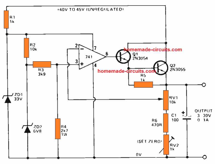
In this configuration, the supply to the 741 op amp is stabilized at 33V by using the zener diode ZD1.
Another extremely temperature stabilized, constant reference voltage of 3V is achieved through the zener diode ZD2, and this applied to the non inverting input of the IC 741 .
The transistors Q1, Q2 are connected with the output of the op amp, and are configured like a variable gain non inverting d.c. amplifier.
This set up has a gain which can be varied from unity to x10, by means of RV1.
This provides an output voltage that is completely adjustable from 3V to 30V through the pot RV1.
The output voltage generated by this IC 741 power supply features a fully stabilized voltage using a negative feedback loop.
Over-Current and Short Circuit Protected 741 Power Supply
The last figure below explains the manner in which an overload protection could be added to the previous IC 741 power supply circuits.
In this design we use a current sensing resistor R7, connected in series with the regulator output.
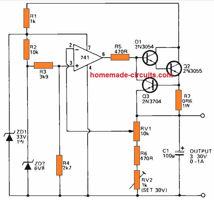
The transistor Q3 which is the shut-down transistor is powered through this resistor R7 and is configured such that its base-collector junction has the ability to short the Q1, Q2 base-emitter junction of the output transistor stage.
Typically, Q3 stays deactivated, and it does not effect the functioning of the circuit.
However, as soon as the output currents of the power supply reaches beyond the 1A mark, a voltage difference of over 600 mV is produced across R7, it instantly begins biasing the transistor Q3 base, switching it ON.
As a result Q3 is forced to shunt the base-emitter junction of the Q1-Q2 output stage to ground.
Consequently, the action causes an instant reduction of the output current, generating a large negative feedback across the connected loop. This action causes an automatic limiting of the output current within the 1A range.
The same procedure is implemented during a short-circuit conditions also, providing a full short circuit and over load protection to this IC 741 power supply circuit.
Improved Design
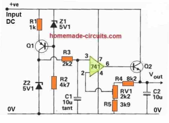
This power supply differs from the previous one in a number of ways. The R12, Q1 Z1 network runs the reference zener Z2 at nearly constant current.
As a result, Z2 is substantially less susceptible to supply changes such as ripple and uncontrolled supply. The R3 C1 (7 HZ low pass) filter significantly decreases the zener diode's ripple voltage and interference.
The output voltage may be changed using the preset VR1.
A precise voltage reference must be implemented if an extremely accurate power supply is desired.
Temperature coefficients as low as 10 ppm / degrees C can be used to get these results.
High stability resistors (TC = 10 ppm / degrees C) and a low drift op amp must be employed while applying this degree of stability.
A main supply filter must also be used to prevent mains transmitted noise (mostly loud clicks caused by electric motors and thyristors going on).
This is a low pass filter network using a passive inductor capacitor that reduces high frequency transients and pops.


Questions & Answers
If the 12V zener diode and 1.2k resistor is removed and P1 of the potentiometer is directly connected to VCC, is the max voltage close to the input voltage
Yes, then the maximum output voltage will not be restricted to 12V.
No, another circuit is fine
I don’t have a 2N3054, TIP35 and a 33V zener diode and I also don’t have a power supply that offers 5A (so the circuit must boost the current). If it is not possible to get 30V at this point 20V is enough
If you don’t have those parts then please find equivalent parts. The circuit will not boost current, in fact it will reduce the input current.
How to modify the circuit so that it gives (max – 30V, min – 1V and current max 5A min 0.01A
Use the following circuit, replace the 2N3055 with TIP35
https://www.homemade-circuits.com/wp-content/uploads/2021/05/3-to-30-V-regulated-741-power-supply-circuit-compressed.jpg
Can a 4k7 potentiometer be installed in place of the 2k2 potentiometer????(4th circuit)
Yes, a 4.7k pot can be used in place of a 2.2k pot.
is Q1 and Q2 NPN
Yes, NPN.
Can we use a 30v power supply and eleminate the ZD1(33v zener diode)
You can use a 30V input power, but please replace the 33V zener with a 15V zener diode.
In the 2nd project can I put a 30v supply and eleminate the ZD1(33v), and what is RV2
Sorry, I think there’s a mistake in the circuit diagrams. The zener diode at pin#7 of IC 741 cannot be 33V, it must be a 15V zener. RV2 is a preset or a trimpot.
Hi I am V.V.Badhrinath (child of 10 years and having electronics as a hobby).Some questions I have are in the 1st experiment.They are:
1.Why aren’t the other pins of LM741 shown
2.Why is shown that pin 7 of the LM741 should be given +18v and pin 4 -9v
please show me
Thank you
Hi VV,
1) The other pins of the 741 are not used therefore not shown.
2) The pin7 of the IC should be higher than 12V and lower than 18V. You can use 0V also at pin4 and check the response, no need of using a negative voltage.
Hi swagatam, can i replace resistor 0.6 ohm 1 watt with 0.56 or 0.68 ohm 1 watt??
Hi Kitten, yes you can do it.
Which one is more recommended? 0.56 ohm or 0.68 ohm?
This resistor determines the max output current.
Output current = 0.6 / Resistor value
I see. I’m sorry for asked a lot, because i’m newbie :), what happens to the power supply if over-current or short circuit? Will it automatic off? Or the voltage becomes 0 V?
If there’s an over current or short circuit at the output, the circuit will shut down and output will become 0V.
if I use transformer, which one is better? CT or non CT?
Non T will be better
Hello Swagatam,
I found an electronic schematic of a power supply, published in an electronics magazine written in English, which despite many google searches, I could not find its author. It has the particularity of using IC 741, its main features are adjustable voltage and current and protection against short circuit.
Could you check if it works?, if you know its author?, maybe there could be an upgrade in that circuit, before proceeding with its construction. Can I upload the pdf?
Thank you in advance
Hello Joao,
Yes, you can upload the pdf to your Google drive or any free file hosting site online and provide me the link here. I will check it out.
By the way I also have an op amp (LM324) based power supply circuit which you can refer to in the following link:
https://www.homemade-circuits.com/universal-variable-power-supply-circuit/
Hello Swagatam, thank you for your reply.
I am attaching the link of the pdf.
https://we.tl/t-IyHEDYVFLJ
Thank you in advance for your availability.
Best wishes
Thank you Joao,
It looks good to me, but the actual results can be verified only after building it practically.
Hello Swagatam, thank you for your reply.
I look forward to hearing from you, about how it works and whether it works. Perhaps you will be able to find out its author, as I have looked in all currently known electronic magazines and in some that are no longer published, but without success.
I only have a copy of this schematic in very poor condition. And I thought it might be a good option for anyone who needs an affordable power supply that’s easy to build.
From what I read on wikipedia.org, the first IC uA741 was invented over 50 years ago, and nowadays there are so many references, and prices…
Best wishes,
Hello Joao, the circuit diagram looks in a very bad shape with so many lines and scratches over the schematic, so I am finding it quite difficult to read the diagram and understand it.
Hello Swagatam, thank you for your reply.
I recognize that too, and I can only sorry it.
The scan was made from a copy, from a copy, from a copy… Sorry I can’t be of more help!
Best wishes
No problem Joao, I understand that, but we tried our best to check it, but due to the many manual pen marks and corrections on the image tracing the actual details became so difficult.
Hello Swagatam.
I would like to know if there is any news about the power supply scheme. It works? did you manage to find its author? the name of the publication perhaps?
Best wishes
Hi Joao, I don’t remember which power supply circuit you are referring to. I have to deal with many circuit ideas everyday so I seem to have forgotten the diagram.
How can I make a +18v and a -9v for this 741ic project.i have a 9-0-9 transformer?
Hello good afternoon, how can I upload a circuit diagram for you to see and can analyze it. Thank you very much.
Sorry Carlos, there’s no facility to upload external circuit diagrams in this forum….
Good day Sir
Thanks once more for the many assistance you offer.
Sir, I want to build a portable PA system with Li-on battery.
I need a dc to dc converter circuit that can convert 3.7 – 4v dc into 9 – 15v dc
Thanks
Thank you Ngang, I would recommend buying one ready-made module from any online shop, since those are extremely reliable and efficient.
Otherwise you could build the 555 design from the following post:
https://www.homemade-circuits.com/how-to-make-simple-boost-converter-circuits/
For the coil use at least 50 turns so that the transistor does not heat up.
This circuits are really inspiring
I love them
i want to circuit in negative voltage 0 to -12 its is possible
you can try this:
https://www.homemade-circuits.com/wp-content/uploads/2012/01/001.jpg
replace D1 with 1N4148, anode pin should be towards P2
Dear Swagatam
Hello. Many thanks for your answer and excellent replacement transistors that you have suggested for last circuit; dear Sir. It is obvious that BC547 with 100mA collector current could not be replaced with 2n3704 of the first circuit for having 300 ma output and I should provide zener diodes of the last circuit anyway, am I true?
Wish you success and all good things
Bye
Frans
Dear Frans, BC547 can be definitely used for Q3 because the collector current is very less for Q3. The output current from 741 is very less due to high values of R1 and R5, therefore Q3 collector has to handle very less current and BC547 will work perfectly.
Zener diodes should be as shown in the diagram.
Dear Swagatam
Hello and thank you very much for all your kindness. Your tips were very helpful and valuable.
Wish you all the good things in your life.
Bye
Frans
You are welcome Frans!
Sir Swagatam
Hello. Many thanks you replied. The circuit that you suggested is excellent but my problems are lacking 6.8 & 33v zener diodes,2n3054Tr, and that I should not go out for shopping because of Corona. I wish It was possible to replace 2n3704 by a suitable one for delivering at least 300ma output.
Bye Sir
Frans
Hi Frans, the 2n3704 can be replaced with BC547, 2N3054 can be replaced with 2N2222 or 8050, but the zeners will need to be exactly as given.