In this post I have explained an effective PWM motor soft start circuit which can be used for enabling heavy motors with a soft start and thus prevent the equipment from drawing dangerous high currents.
Why a Soft Start
High wattage motors such pump motors or other forms of heavy industrial motors tend to draw huge current during their initial power switch ON, which in turn impacts the associated fuses and switches adversely causing these to either blow of or degrade overtime. In order to remedy the situation a soft start circuit becomes highly imperative.
In a few of my previous articles I have explained regarding a related topic, which you may learn comprehensively through the following posts:
Soft start circuit for pump motors
Soft start circuit for refrigerators
Although the above designs are quite useful, these may be considered slightly low tech with their approach.
In this article we'll see how the process may be implemented using a much sophisticated PWM based motor soft start controller circuit.
Using PWM Concept
The idea here is to apply a gradually incrementing PWM to a motor each time it's switched ON, this action allows the motor to attain a linearly increasing speed from zero to maximum within a stipulated period of time, which may be adjustable.
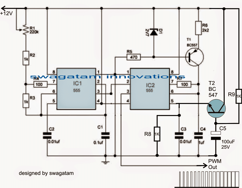
Note: Please use a Darlington BC547 configuration at pin#5 of IC2 instead of a single BC547. This will produce a more effective response compared to a single BC547
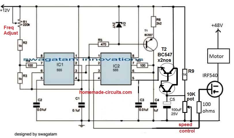
Example circuit for a variable 48V motor controller with soft start
How it Works
Referring to the figure above, the production of the linearly incrementing PWM is achieved with the help of two 555 IC, configured in their standard PWM mode.
I have already discussed the concept elaborately in one of my earlier articles explaining how to use IC 555 for generating PWM.
As may be witnessed in the diagram, the configuration employs two 555 ICs, IC1 being wired like as astable, while IC2 as a comparator.
IC1 generates the required clock signals at a given frequency (determined by the values of R1 and C2) which is applied to pin#2 of the IC2.
IC2 utilizes the clock signal to generate triangle waves across its pin#7, so that these may be compared with the potential available at its control voltage pin#5.
Pin#5 acquires the required control voltage via an NPN emitter follower stage made with the help of T2 and the associated components.
When power is switched ON, T2 is fed with a ramping or a gradually increasing voltage at its base via R9, and due to the proportionate charging of C5.
This ramping potential is appropriately duplicated across the emitter of T2 with respect to the supply voltage at its collector, meaning the base data is converted into a gradually increasing potential ranging from zero to almost the supply voltage level.
This ramping voltage at pin#5 of IC 2 is instantly compared with available triangle wave across pin#7 of IC2, which is translated into a linearly incrementing PWM at pin#3 of IC2.
The linearly incrementing process of the PWMs goes on until C5 is fully charged and the base of T2 attains a stable voltage level.
The above design takes care of the PWM generation each time power is switched ON.
Video Clip:
The following video shows a practical test result of the above PWM circuit implemented on a 24V DC motor. The video shows the PWM pot adjustment response of the circuit on the motor, and also an additional battery indicator LED response while the motor is switched ON and OFF.
Integrating a zero Crossing Triac Controller
In order to implement the PWM motor soft start circuit effect, the output from pin#3 of IC2 is required to be applied to a triac power driver circuit, as shown below:
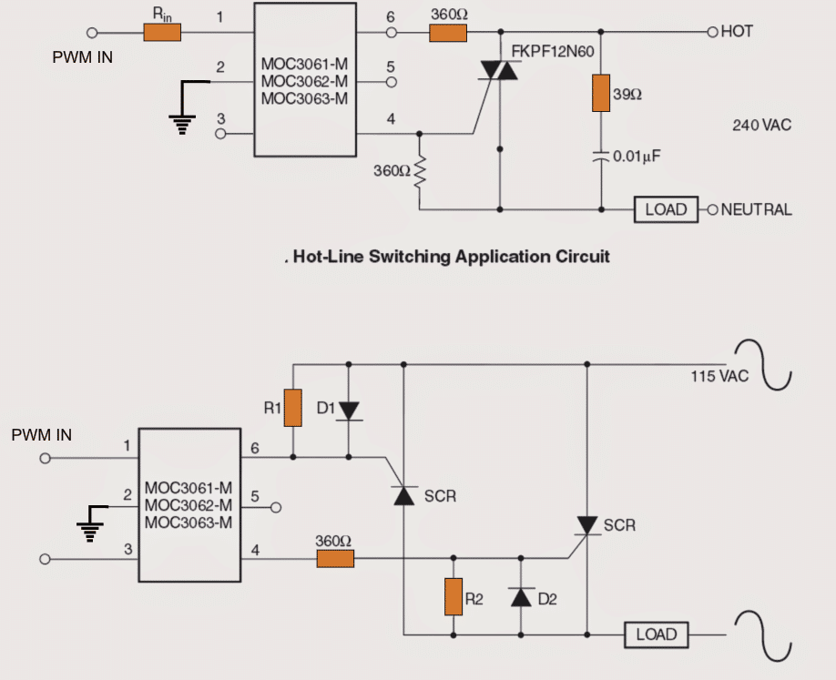
The above image shows how the switch ON soft start PWM control may be implemented on heavy motors for the intended purpose.
In the image above we see how triac driver isolators with zero crossing detector can be employed for driving the motors with the linearly incrementing PWMs for executing a soft start effect.
The above concept effectively takes care of the start ON overcurrent situating on single phase motors.
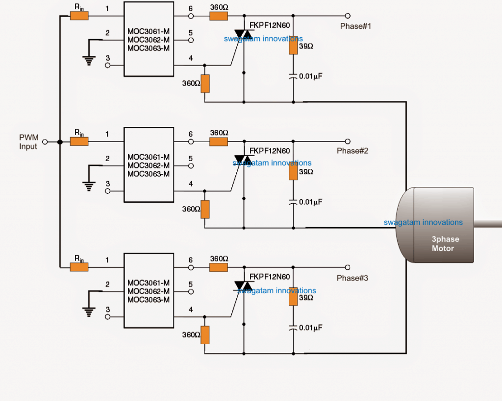
However in case a 3 phase motor is used, the following idea can be used for implementing the proposed 3 phase soft start on motors.



Questions & Answers
sir i saw your article for 1watt led driver Transformerless circuit.
https://www.homemade-circuits.com/2012/03/how-to-make-simplest-1-watt-led-driver.html
i this you used 1uf/400v PPC capacitor for producing 350mA current to drive 1 watt led.
but in your 2nd article for Calculating Capacitor Current in Transformerless Power Supplies.
https://www.homemade-circuits.com/2015/01/calculating-capacitor-current-in.html
you said 1uf/400v PPC capacitor can produce approx 69mA current.
then how it is possible 1uf/400v PPC capacitor can produce 350mA current to glow 1watt led.. if 69mA current is used to glow LED then led glow very dim.
plz explain me. i cant understand
Yes that's right, the proposed circuit will light up the LEDs at 70mA……….to counter this you can use 4 LeDs (1 watt) in series to produce an equivalent light of a 1 watt LED….4 LEDs will mean more money spent on the LEDs, but since it will not demand the need of heatsinks and special aluminum back PCB, so the cost will balance out ultimately
sir previous i glow 3 led of 1watt in series through 12V 500mA local ac adapter. but the cost of this adapter is approx 80rs.. sir can u give me 12V or 18V 500mA ac adapter circuit.? which i can build easly at home at cheap price..
thnkx in advance.
Good day sir, i’m DIY try to replicate your circuit but using microcontroller. I’m doing the circuit on a donut board, i‘m testing the circuit with single phase then i will switch to 3 phase after all 3 circuit is working,what is the function of 39ohm and 0.01uF capacitor parallel in the AC circuit, i try to hook up my small AC motor with power rating 6-10W it turning just with the 39ohm resistor and 0.01uF capacitor,so i decided to resolder and samething happen, i try to switch to a larger motor which rated 240VAC 2.5A my 39ohm 1W resistor got burned, do i need that? what is the function of 39ohm and the capacitor?
i tested my first first circuit it work fine but my motor is jerking while in low speed, but the second and third circuit have the same problem of motor move without any signal from dc side
Good Day Neoh, the 39 ohm and associated series capacitor are used as snubber network for protecting the external triac from motor back EMF and spikes. You can use a wire wound 1 watt resistor for the 39 ohm. It is as recommended in the datasheet of the MOC opto coupler
Thank for the fast reply, hmm… protection okay, but if i connect the 39 ohm resistor and capacitor only, without the rest of the circuit, will the motor move? because I have try that to my small induction single phase motor and it is moving. I’m wondering is that suppose to happen?
Do you mean to say you are not connecting the external triac? In that case the opto-coupler will also burn due to high current from the motor….smaller motor may have worked through the opto internal triac but this is strictly not recommended.
I’m sorry because maybe I’m not E&E based, my explanation will be lenghty
I’ve learn the hard way thro this project in the past few month, here is what i get, i have done solder the circuit board with donut board, i tested the circuit with a small ac motor with power rating of 6-10W
and the first phase circuit work well, my second phase have some problem that i didnt know, which is my motor is rotating without dc signal, so i guess it must be short circuit, and i try to test every connection by multimeter and i cant find any short circuit, then i guessing there must be arcing due to the spark i saw it at my dc side circuit, so i resolder everything on a new board, and tested the circuit connectivity each time i solder a new component, after i start solder the 39 ohm resistor and 0.01uF capacitor the problem still go to the second phase circuit again the motor move without any connection from extrnal triac and octo-coupler i have not solder the triac and the MOC ic yet on my new circuit board but my motor is moving, i can find any problem so i decided to have a try on larger motor which rated 240vac 2.5a and my 39ohm 1watt resistor go kaboom with some obvious spark and the circiuit is disconnected, after unplug the wire i check the resistor with my multimeter in resistance mode and it show OL… unable to mesure it stuck there i was frighten by the spark and seek for some help…
I’m mechanical based and i learn some microcontroller like arduino and mcu from the internet, this is where i started to pickup all electronic knowledge without any mentor, sorry for the lengthy explanation
OK, I guess you are referring to the last circuit which is a 3 phase design? Did you use the PWM input across the opto coupler input pins?
What frequency and PWM did you apply here? I would recommend initially using 3 bulbs instead of the motor across the triac to check how the bulb intensity responds to the PWM input.
Please confirm then we can move ahead.
I use arduino uno to generate the pwm, from a 10k pot by analog read to analog A0 pin,and pwm output after mapping the value to 0-255 at pin 6, only one of the circuit (phase 1) is respond to the pwm but with jerking motion until some point which is very close to maximum pwm then the motor move smoothly, phase 2 circuit moving all time,phase 3 circuit only on at max speed and off at very low pwm
I cant find fkpf12a60 at local store, i only found one less current rating BTA serise BTA06-600c which only have 6A current rating
The arduino signal is 5v and i done some math with ohm‘s law which give me approx 240 ohm if i limiting the current to 15mA
For the MOC chip, I’m using MOC3061 which current rated 15mA for the built-in LED
All resistor i’m using is rated 1W except for the DC PWM side circuit i’m using 1/4W
Are you using 3 different PWMs for the 3 MOCs? The IC 555 PWM must be connected in the following manner:
Yes BTA06 will do.
Nope I’m using single PWM signal for all phases. I’m not using the 555 for the soft start.
I’m using Arduino instead.
Since the motor is AC, a basic PWM control might not work. Your PWM must be formatted in the following manner, and should be variable through two independent modes:
Please test the output with 3 incandescent 60 watt or 100 watt bulbs connected across the 3 phase lines.
If the bulbs intensity varies uniformly across the 3 lines, then, according to me the motor will also respond in the same way.
Rahul, Rs.80 is also cheap, making it at home will cost almost this much…the transformer will cost around Rs.40, and the rest Rs.15/- so that's Rs.55 plus a lot of hard work…
anyway, you can try the following circuit:
https://www.homemade-circuits.com/2012/02/how-to-make-current-controlled-12-volt.html
thanku sir..
i saw your another smps led driver circuit.
https://www.homemade-circuits.com/2014/02/simple-1-watt-to-12-watt-smps-led.html
this two diode are not available in market.
1. ST1MDICT
2. STTH1R06A.
Any alternative of this two diode.?
plz tell me..
and if i make this circuit it get work on 220/230VAC mains ???
Hello Rahul, you can use 1N4007 for ST1MDICT, and BA159 for the other one.
yes it's designed to work with any input between 80V and 270V AC/DC
Plz tell me the ckt pf 220v ac to 220v dc with dc voltage regulator
you can try the following circuit:
https://www.homemade-circuits.com/2015/05/smps-mains-voltage-stabilizer-circuit.html
hi Swagatam. i want to know that the circuit mentioned has any affect on electricity consumption? as motor needs more current in starting phase? if yes then can this circuit be used with air conditioners compressor?
Hi Muhammad, yes the current will be initially low and will gradually increase as the PWMs widens so this will enable a slow start or a soft start to the motor.
the time delay can be altered by altering the value of C5 appropriately
thanks for the reply swagatam. so can i use this circuit with my ac? i am also trying to make stablizer for my ac as those available in markets are very expensive. which of ur stabilizer designs will work with that and what rating of auto transformer should be made for said purpose?
yes you can use the above designs with any motor as per the indicated methods.
here's one stabilizer circuit which you can try for your preferred application
https://www.homemade-circuits.com/2011/12/how-to-make-accurate-7-stage-op-amp.html
thanks for the reply Swagatam. so can i use this circuit with my ac? i am also trying to make stabilizer for ac as those available in market are expensive. which of your stabilizer designs should i consider and what should be the auto transformer rating for the said purpose? plz also let me know that can we convert normal ac into inverter ac?
ac for air conditioner
and is it possible to convert normal ac into inverter air conditioner?
it looks like it can used like an inverter AC, but it will need to be thoroughly tested first and experimented so that the results become perfectly verified.
you will need the assistance of an expert engineer for implementing the tests.
I understand the first circuit sir.please give the information about a second circuit sir.I am planning to implement it on my college lab as my mini project. Please reply sir
the second circuit is meant for AC operated motors, the PWM from the first circuit is fed to pin1/2 of the optocoupler in order to implement the soft start over the connected AC motor on the right side with the triac stage
Sir I have some doubt please clarify it. In our college while performing the experiment we use auto transformer as a starter by adjusting there tappings we can start the ac motor smoothly. Disadvantage of auto transformer is its more costier. While seeing this circuit I hope that its cost less while comparing to auto transformer so that I planned to implement it. By pwm technique we need to adjust the pulse given to a motor at the starting and finally width of a pulse becomes maximum so that motor starts smoothly as per your first circuit how can I vary the pulse in a first circuit I need to use a pot for controlling the reference voltage?
2)sir please give detail information about optocoupler I didn't know any think about this please share any other website link about optocoupler.I need a detail information about the optocoupler u mentioned here.please help me sir. I am new to electronics but I have a eagerness to do it
Vijay, you can vary the PWM manually by replacing R9 with a 1K pot, and by eliminating C5.
Opto-couplers are devices which enable isolating two stages in a circuit where the two stages may be at extreme levels and needs to be completely isolated….for example in SMPs the output DC is controlled by the input AC stage through a feedback from the DC stage to the Mains AC stage through an optocoupler.
the MOC series which is shown in the above article is a more advanced opto, since it has a feature called zero crossing detector….you can check the datasheet of this part for a detailed info.
Thank you very much sir for a detailed info.I appreciate your fast reply sir.keep it up sir.we need a person like you for our doubts
you are most welcome!
Hello sir, i'm interested in using this design on an old monarch lathe. It's a large machine running 230v three phase power, would this design work in that application?
Hello Thomas, according to me it should work.
but make sure you confirm the PWM circuit first using a scope and only then integrate it with the last opto circuit
…also make sure the triacs are adequately rated for handling the machine current.
Has it been practically tried with the triac and the opto? Or tried just till the 555 output. .
no, the opto section is not yet tried practically, but according to me it will work without any doubt
Sir, opto coupler with zero cross detection is not working for pwm input with frequency oh 10Khz
Swaroop, use a Darlington transistor for T2, and increase the value of C5 to 1000uF and check again.
Hello Swagatam, first of all BIG THX for your awesome work!
I am going to build a 1-phase-to-3-phase AC motor inverter. It will use a separate opto-isolated IGBT driver on 20 VDC. The diagram above could be used as the initial logic circuit to supply the driver with PWM signal. I am wondering how would your diagrams change if I intend to use 5V logic circuit instead of 12V. Any suggestions?
Thank you Julio, the first circuit can work with any voltage between 5V and 15V, so there's nothing that would need to be changed for a 5V operation, if possible use the CMOS (7)555 ICs instead of the indicated analogue 555 ICs, for getting perfect results.
in fact I am thinking about using a 556 IC. It's two 555 timers in one package, isolated, only sharing Vcc and GND. I have to check if there's a CMOS version of that. Thank you.
OK, thanks!
I'm a noob, but maybe it will help others wondering like me:
I checked on my parts supplier website. They have two kinds of 555 and 556 ICs – 4.5-18V 0.5MHz or 2-18V 2.7MHz. While not specified (on their webpage), those second ones are CMOS. Seemed like an overkill at first for 20KHz, but now it makes perfect sense. Thank you again.
you are welcome julio!
Mr Majumdar can i use the above soft starter circuit to an underwater pump 30hp?the voltage is 400V 50hz 3 phase..is there any problem with the starting current?
Mr.Giannis,the first and the second circuits are confirmed but the last circuit is not yet tested…however I believe it would work as proposed in the article….you can try it out there's no harm in it.
The triacs could be replaced with the following one for max safety and reliability:
https://www.homemade-circuits.com/2012/12/high-current-triac-bta41600b-datasheet.html
Ok ill try it..Thank you very much!
good day sir., i would like to ask if you have a complete calculation of the ckt i want to how did you arrive with those components im an electrical student i only have little knowledge of electronics. thank you sir
the subject can be quite extensive, not possible to explain in few sentences, because there could be strings of explanations one relating to the other and will need to be too elaborate.
ok sir. thank you…sir i did simulate the pwm but i didnt meet the expected output…i did follow the connection.
Jemimah, simulation results are never reliable, please build it practically and check with a scope.
thank you sir i will make as soon as possible and tell you the result…sir i would like to ask what is the process in the triac power driver? what is the use of the triac and optocouplet that it can create a soft start in motor?.. thanks sir
the opto coupler acts like a buffer in between the PWM source and the triac and makes sure that the triac is driven perfectly by considering and adjusting many parameters which relieves the user from designing precision external triac driver stage and related protection circuitry.
good day sir..based on my research, there s already a triac inside the optocoupler, so why use another triac that is connected to pin4? thanks sir.
the internal triac is a low power triac and cannot be used for powering heavy loads.
sir, in the three phase soft start ckt, what is the value of the resistor connected in pin 1?
it can be any value between 1k and 10k
good day sir.we already construct the pwm and the circuit for three phase, we applied it into a lamp instead of a motor..why is it that the circuit did not work on a lamp?
that's not possible, in fact an incandescent lamp would be more responsive to a PWM dimming….however if you are referring to a CFL then may be it could be a valid occurrence.
sir regarding to her question..the output of the pwm is directly 12v output…why is it so?
because the supply is 12V so the output from the IC will also be at 12V
Good day sir. Sir I want to ask about the comparator. Can I ask for its calculation?
Good day Rea,
you can find the details here:
https://www.homemade-circuits.com/2011/12/constant-torque-dc-motor-speed.html
good day sir. why is it that the output voltage that is to be supplied to the motor is only 7volts, the 3 wires connected to the motor are all 7 volts.
good day ecnemay,
are you referring to the third circuit?
did you connect mains 3 phase across the shown points in the third circuit? please elaborate on this?
good day sir, we checked again the voltages of the three wires connected to the motor, it all turned out 210V. the tester we used in which it reads 7V is damaged.sorry 🙂
OK that's fine…thanks for updating the fact.
good day sir.. what are the specifications of the motor used in your design?
good day ecnemay, all DC motors will work with the the first circuit after a transistor driver stage and AC motors with the second and the third circuits.
power of the motor will depend on the rating of the power devices used
sir if you are going to run a motor using this design, what motor will you use? in terms of its power. .
and also sir, if we used 0.5hp induction motor, do we have to change the ratings of the components (e.g. resistors/ capacitors)? or do we have to modify the circuit.
you can run a 100 watt motor with the second and the third circuit
sir, what are the voltage ratings of the three 0.01microfarad in ckt 3. we used 25v capacitor but it burnt out. we replace it with 0.01microfarad 200v capacitor, but there is no output voltage when it is connected to the load. if it has no load, the output voltage is 230v balance. what do you think is the problem in your ckt..? why is it that the voltage is zero when connected to the load. thanks.
ecnamay,
the voltage rating of the capacitor should be obviously high, since you are working with mains voltage. it should be 400V in the input is 230V…
You might have done something seriously wrong or or may your parts are of low quality and that's why not working.
the circuit idea is perfect and will work immediately but only if it's done by proper understanding.
we tried it in a single phase motor, it did work but no changes in its starting current.
did you confirm whether the first circuit was correctly built or not? and whether it was generating the PWMs or not?
Dear i'm having 330ohm instead of 360ohm is it enough? In the third circuit…
yes that will do!
Hi, could you tell me what the value and wattage of R1 + 2 should be in the third circuit? Also the amp rating of D1 + 2. I will be using the circuit to soft start a 1 1/2 HP pool pump, 120 VAC 12.5 FLA.
Hi, all resistors can be 1/4 watt rated, the diodes can be BA159
What about the values of R1 + R2 ?
360ohm 1/4 watt will do for both
Hi mr. Swatagam
Could you pls. give the parts spec. for the 110v " Hot line switching circuit" the one with the SCRs
or if i could use the 220v circuit for 120v line what would be changed for that?
(Benchsaw 110v 12amp)
Your input is very well appreciated.
Roger
Hi Mr.Roger, R1, R2 can be 360 ohms 1/4 watt and the SCRs rated at 15 amps
I believe that the 220V version using triac would also work normally with a 120V input and loads
thanks, much appreciated
Hello, i am using your circuit to soft start a engine starter (car), but it is going from 0 to 12V really quickly, changing R1 and R3 to 1M went from 1ms to 32ms of rising time, but this is too much low for me yet, i need it to be around 2-3s of rising time. Do you know what i could do ?
Really thanks in advance.
Hi, R1 is not related to PWM adjustment, you should try increasing the value of C5 for getting lengthier soft starts…if possible use a Darlington for T2 for a better response
Swagatam, I have been reading your design for a PWM-based soft start for a motor. I really like the 2 x 555 design (which, I guess, could be implemented with a 556 dual timer chip). What puzzles me is the interface between this PWM circuit and the mains electricity. The output of the PWM circuit is asynchronous with the mains, but the 3061 forces synchrony with the mains (50Hz in my case) through the zero-crossing detector. You didn't give the frequency of the oscillator, but I presume it is faster than the mains. I don't doubt that you have tested it, but I can't see how it works. As my motor is a universal motor (in a table saw), and would run quite happily on DC, would it not be a better idea to rectify the mains for the motor, then use the PWM to switch an IGBT on the earth-side of the motor? That way, the mains frequency doesn't really come into the question. I guess it would need a transistor between the timers and the IGBT – even though the gate is insulated.
Thanks Mij,
you are right the design looks quite complex to interpret and set…. the PWM is actually asynchronous with the 3 phase cycles that's the real issue. yes The frequency will need to be around 4 to 5 times faster than the 50Hz or 60Hz.
I have been struggling with a simlar issue in the following article too:
https://www.homemade-circuits.com/2016/07/3-phase-induction-motor-speed.html
and therefore the mosfet bridge driver concept appears to be a much easier option than through triacs, I'll try to update one soon here.
In fact the following concept could be tried for implementing a PWM soft start using mosfet drivers
https://www.homemade-circuits.com/2016/12/diesel-generator-rpm-controller-circuit.html
this shows a single phase control, but the same could be implemented using a 3 phase driver IC.
T1 is for ensuring that the PWM do not get affected with a fluctuating DC supply to the circuit….if your DC is constant you can remove the T1 and the associated parts…
Hallo. I have two questions.
Would be possible use the 3 phase softstart use in Europe? There is 3 phase voltage 3x 400V.
And, I'm not sure, what is PWM input in left side of the circuit. Is possible use a switch?
Regards,
Mike
Hello, yes the design can be used for any 3 phase induction motor in any country, the PWM input is derived from the first circuit..and this must be set correctly for achieving the soft start.
hii
can u please tell how much apprpx. current can be reduced if we use it with single phase induction motor 3 hp runnig amp at full load is 15amp.
the current will start from minimum and then settle to the specified normal value (15 amp) with this soft start circuit, however the above design needs some corrections , I'll try to do it soon.
Hi Swagatam, glad to come across your site. Thanks for posting all good ideas. I have a question on the above PWM Motor SoftStarter circuit.
Can I replace FKPF12N60 with BT139 / BTA16/600B etc. ???
Thanks Chandra, it’s my pleasure!! yes you can try a higher rated triac, because I am sure the MOC is rated to produce at least 30mA output to trigger these triacs satisfactorily.
Thank you very much Swagatam for quick response.
you are welcome Chandra!!
Sir, can i use the above soft starter circuit for 10HP 3 Phase motor instead of using star, and after soft start can i bypass?
Swaroop, you can try it, by suitably adjusting the PWM duty cycle…
use a Darlington for T2 and use 100K for R9
ok thank you sir.
Hello. Very interested in your PWM generating circuit. Your motor driver circuits with the triac and the SCR are for AC motors. Like your correspondent who wants to soft start a car starter motor, I require to soft start the starter on a motorcycle. Both of us need a DC driver circuit providing rather large currents. Can you help please.
Could you please specify the motor specifications, is it a DC motor?? If it is then you can easily drive it by usingg a TIP35 transistor with pin#3 of IC2 in the first diagram, and by attaching motor between the positive battery supply and collector of the transistor…the emitter will connect with the ground of the motorcycle or the battery negative, and the base of the BJT can be connected to pin#3 through a 220 ohm 1 watt resistor
Same as Peter, I need to soft start a DC motor but mine runs at 30 Amps thus TIP35 may not be up to the task; browsing around I found a transistor NTE29 that I guess can be wired the same as the TIP35 but since I’m not into electronics thought of asking for your recommendation.
Please use a MOSFET instead, it will be more efficient than a BJT
Thanks Swag! But please bear with me as my electronics knowledge is very limited thus, no idea how to select a MOSFET that may constantly run with a 30 Amps load; could you suggest one? Will it be connected the same way as the BJT?
Hi Alejandro,
Yes you can connect it just like a BJT, gate to pin3 of IC, drain to motor, source to ground, or negative supply line. The MOSFET can be IRF540 for a supply within 100V
Great!
Thanks a lot!
Hi,
Could you please tell me the value of resistor Rin.
Thanks,
Mohan
you can try 4k7 resistors
Hi Sir Swagatam, we have an electric tricycle with a 500W 48v differential motor with 3 speed switch and powered by a 48v 20Ah battery.
Would you please recommend a suitable soft start circuit for this kind of motor ( differential )
if ever, should i power it separately or just tap it to one of the 12v from the 48v battery supply?
Hi Amor, although I do not know much about differential motors, I believe the second circuit from the above article will be able to implement the required slow start to your motor perfectly, you can give it a try…
Thank you Sir Swagatam, is there any replacement for the mosfet IRF540? what about F9540N?
about the watt ratings of the resistors, are they all 1/4 watt?
Hi, F9540N is same as IRF9540N which is the P version of the IRF540, it won’t work since the soft start action would be simply reversed…it may work if a NPN BJT is used as the buffer in the middle
Good day Sir Swagatam,
how could i integrate the above 2nd circuit in a electric rickshaw unit that has a 3 speed and a reverse functionality? does the soft start also affect the reverse mode?
it is okay to charge the battery (48v ) from ac outlet while the soft start circuit permanently connected?
Good Day Amor,
Your motor’s negative is at the moment connected directly with battery negative, that will need to be removed and connected with the shown mosfet’s drain pin.
after this the circuit and the 48V supply will need to be configured with a DPDT switch such that both the motor and the circuit are switched ON simultaneously each time the switch-ON operation is conducted.
Hello Sir Swagatam,
Should i put a large heat sink for the irf540?
what is the wattage of the 100 ohm resistor at the base of the mosfet?
Thanks,
AMOR
Hi Amor, yes you will have to put a large heatsink on the mosfet, the 100 ohm is 1/4 watt rated
Hello Swag,
I was just wondering how to modify this schematic to work also as soft start / soft stop for led strips. What I figured out is something using a 3rd 555 to generate a delay for power supply switch off and a NAND to control R9 (ON state -> OFF state).
Have you got any other suggestion please?
Hello Astercaster, No external circuits will be required for the mentioned modifications. You can simply connect the LED strip with the mosfet in the second diagram and get the require results. The LED will fade-in and fade-out each time the ON/OFF switch is operated.
Hello Swag. Thanks for your dedication to this page.
How do you go about calculating Rin. You suggested 4k7 but the datasheets suggest that the resistor should follow the Ift of the optocoupler chosen. The voltage from the PWM circuit should be around 11V, so if I had to choose 10mA as If doesn’t this give for a 1k1?
You are welcome Ronald.
In electronics resistor values are never critical unless it is related to time delays or frequency. For LED current limiting the parameters are not so critical.
The switch ON specification of the internal triac of the opto is also not so critical, that implies within a certain margin the switching can be implemented normally.
With a 4k7 resistor also the LED switching will be optimal enough to trigger the triac, with a 1.1K it will be a little sharper, but in both the cases the trigger will happen normally.
Thanks. Much appreciated.
Good day Sir Swagatam,
I made the 2nd circuit Sir but its not working properly
when i apply power to the circuit the motor never gaining its full speed
i mean the speed of the motor remain in the soft rotation
but when i turn the pot (R1, R8) that’s the only time the motor will gain its max speed.
I’m using a 12v cpu fan to test the circuit and using the same power source both for circuit and fan.
what do you think i am missing Sir?
Thanks,
Amor
Hi Amor, A CPU fan works on BLDC principle, and I don’t think a BLDC fan would suit the second circuit.
Alternatively you may try replacing the BC547 with two BC547s joined in Darlington form, I think this could help to solve the issue
Thank you very much for addressing our concerns Sir,
instead of using two bc547 what specific darlington transistor i could use inplace of bc547?
Thanks Amor, You can try BC517 if it is available to you
Greetings!
Hello Sir, i’ve tried your recommendation but there’s no changes happens.
when i set the pot to low then the motor remain in a slow rotation and if i set to pot to higher then the motor will start and remain at its constant high speed the same happens when i use a 12v led strips.
Hi Amor, first confirm whether your circuit is correctly working or not by replacing the motor with a filament bulb (rated to work with the existing DC supply). If the bulb illumination varies uniformly, then that would would indicate the motor is not suitable to work with normal PWM application, and might require special ICs or drivers for the operation.
Hi. I admire you so much. I watched the soft start circuit. The problem I want to ask you is whether to use parallel 2 irf540 to make sure it is better.
Looking forward to your help.
Hi, Thanks, it’s my pleasure. A single MOSFeT IRF540 looks sufficient for most of the applications, however if your load current is higher than the IRF540 capacity then you may need to add a second one in parallel
Hello Sir,
I think my circuit is not working properly because when i connect a filament bulb there’s no gradual changes on the light intensity.
i thoroughly checked my connections and it is exactly the same with the 2nd circuit above.
may i ask Sir if the T1, T2 or the R8 (pot) connected the right way?
Please bear with me for asking too much Sir, just want to make it works for the benefit of my old man.
Thanks,
Amor
Hello Amor, everything is correctly connected in the circuit. For further verification you can compare it with the following original diagram. Only R3 may be missing in this diagram, but R3 was purposely added in the above diagram because without R3 the IC1 sometimes stopped working:
I need a vfd circuit for 3phase induction motor
Hello Swag! I was wondering about the start capacitor for single phase motors, is it already implemented or is some type of work around involved to get to work properly? I wanted to implement a soft start circuit for my drill press, as when it starts it really jerks hard on the pulleys and belt, and I believe over time this will be harmful to the drill press and components….it is a 1/3 HP, 7 Amp, single phase, AC induction motor with a start capacitor…if so which circuit would suit to my needs the best? And I would like to thank you for the professional help in advance, as there is no cooler electronics site on the web as yours! You do a great service for hobbyists and professional’s alike, and I thank you for that Swag!! Sincerely, Michael Sakach- electronics hobbyist, and Swagatam follower!!
Thank you Michael, it’s always a pleasure helping interested hobbyists like you!
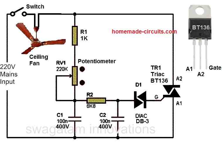
As far as I know single phase induction motors are not self starting, and needs an external force to initiate rotation, so may be your motor already has a capacitor for enabling the initial pickup for the motor.
To control initial start up speed I would recommend trying a phase-chopped triac based circuit, similar to our home dimmer switches but with a heavy duty triac.
You can experiment this by manually controlling a series connected dimmer switch with your motor. If you are able to control the speed with this devices then you can either implement the slow start manually each time you start your machine, or automate it using one of the designs presented in the following article:
https://www.homemade-circuits.com/adding-soft-start-to-water-pump-motors/
I would soon merge this article with the above one since both basically have the same purpose
Let me know if you need any further help:)
Good day Swag. Please what can i adjuat in the circuit to ger 380hz frequency from the pen
Thanks
yes you can get it by adjusting R1, or C2 individually or in a combined way
Dear swag
Will this circuit work with 5vdc? what modfications will i do on the circuit to power it with 5v DC instead of 12Dc thanks
Hi Matthias, It will work with 5V also without any change in the design, you may only have to increase the value of C5 to 220uF or may be more!
Hallo Mr.Swagatam,
thanks for your inspirational article.
I would like to ask you whether it is possible to use an readymade module as a PWM?
Can I use this module for soft start of 3 phase and 1 phase motor? Or will it be better to build a PWM circuit according to the diagram in the article?
Thanks
Michal
Hello Michal, the mentioned module will also work, since SG3525 has an in built soft start facility
i scrolled back up the page and i didn’t see a SG3525 module mentioned anywhere.
The comment was asked with reference to the IC SG3525, which has an in built PWM feature, it is not discussed in the above article.
Hello. I have some questions regarding the dual 555 circuit.
In my box of ICs, i have 1 bipolar NE555N and 1 CMOS TLC555CP. That is all i have in stock.
1a. Could i use the TLC555CP for one of the 555’s.
1b. If yes, should i use it as IC1 or IC2. Which position would be best?
I checked the Ti website and the TLC555CP can sink 100mA of current and source 10mA of current on pin 3.
As you know, the NE555N can sink/source a lot more current.
2. I will be powering the PWM circuit with 12V and using the PWM output to drive a MOC3041 as in your “integrating a zero crossing triac controler” schematic. For Rin of the MOC3041 i have chosen a 3.3K – is that ok?.
I will be using 2 BC548’s in a darlington configuration as per your recommendation and increasing the value of C5 to 1000uF to give a longer soft start duration.
Hi, you can the ICs in any random positions since there are no critical restrictions on them. However, putting the CMOS IC 555 in IC2 position may allow the use of a single BC547 at its control pin instead of a Dralington.
The remaining considerations look OK to me.
Hi. Great web site and thank you for all the valuable information.
Will the triac schematic work with a small synchronous AC motor?
Thank you.
Hi, thanks for liking my website, yes you can use the triac circuit for applying soft start to an AC motor, you can increase C5 value to other levels for obtaining the desired amount of slow start.
Hi Swag.
Actually since it is a synchronous AC motor I am trying to turn it off for 5 sec and then on for 5 seconds, for a duration period of 1 minute and THEN 1.5 MINUTES WITH THE ON-OFF. Is a uC in place of your dual 555 ckt the only way to do this?
Thanks for your help.
Hi Fred, if you want programmable ON/OFF rates varying with time then you will have to use a uC…the above circuit can only produce fixed ON/OFF rates
Hello,
thanks because you share information with as. Your subject about soft start is very good ! If possible to connect, on last schematic (three phase soft starter), induction asynchronous motor 0.25kw 3F/400V. I’m a little concerned about the 360R 1/4W resistor.I’m afraid that too much current will kill MOC3063? I planning to drive that circuit with MCU, which max. frequency can use for PWM for that circuit ?
thanks a lot again on a wonderful post.
Hi, thanks, the current will actually pass through the main external triac, so the MOC will not be affected by the high current. However, perhaps the resistor wattage can be increased to 1 watt or higher for increasing its own safety
Thanks for fast response. I have one more question. I cant find in my country fkpf12n60. What is maximum value for IGT ? I must find replacement…
You are welcome…it’s 30 mA
you can probabaly try this:
https://www.st.com/resource/en/datasheet/btb10.pdf
Hi WordPress,
I am very happy to be interested in you, I am a person who does not have a lot of electronics expertise, I can draw the circuit for you, you can help me see that circuit when it is actually usable. My desired purpose is to soften the engine and adjust the speed when running after every Dc power on / off. and I want you to show me how to turn on / off so it doesn’t affect the board.
Look forward to your help.
Looking forward to your early reply.
Attachments I have sent via the address WordPress
Thank you Phuong, Appreciate your interest in electronics.
You can try the second concept explained in the above article. It will work as per your specifications.
Hello Swagatam,
To minimize space is it possible to replace the PWM generator as 1st circuit in this post with a TL494, if possible could you design the circuit for us please. thanks.
Hi Syarif, you can refer to the last circuit from the following article:
https://www.homemade-circuits.com/tl494-datasheet-pinout-application-circuits/
you can see pin1 which decides the output PWM…if you replace the 100nF capacitor with a 100uF, that may enable to get a slowly rising PWM across the output pins.
Hi Swagatam,
Thank you for your prompt reply, I will try it, thanks again.
Hi Swagatam
Thanks for your design, I have 1500W sliding mitre saw ( Metabo kgs254m) , I looking for circuit to make soft start can I used this circuit?
Thanks
Hi Nima, if the saw is DC, then definitely you can use the concepts explained in the above article.
Thanks for your reply, unfortunately my saw motor is AC, can you design circuit to can used for AC motors please?
I find circuit design in web in link below, biggest problem with this design some components very difficult to find and expensive In United kingdom ,I find review of this design some people said same.
I really appreciate if you can design soft start circuit to work with must power tools and much easier and cheaper please.
Thank you
No problem, you can modify the second circuit from the above article by adding a bridge rectifier with the load (motor) as shown in the following diagram
Thanks, this is fantastic, I have to choose first design or second 48v ?
My I ask you do i need to supply 12v dc to circuit?
Also what resistor capacity (W) I have to use it and what voltage for c1 c2 c3 c4 c5 please .
Thank you
I think the circuit needs a small correction, the motor should be in series with one of the AC lines. Meaning, the indicated motor position must be shorted with wire link, and motor should be positioned in series with one of the lines which is going to the mains inputs.
Yes the circuit will require a separate 12 v DC for operation. All the resistors are 1/4 watt 5%, you can apply the mosfet configuration with the first design also. Capacitors C4, C5 are electrolytic, remaining can be ceramic disc.
With regards to soft start of mitre saw This will only work with input being switched
Do you have a circuit for soft start that will work when output is switched IOW when the circuit sees current drain It will kick in the “delay” or soft start circuit ?
It is possible to modify the above shown design for the purpose, provided the load is also DC load and has a common ground with the PWM circuit.
As mentioned its a mitre saw so its AC not DC
I have a question that refers to old Lionel train motors.
When running a train into a block signal area the power is cut at normal running voltage of around 12 to 16v.
upon restart the voltage comes back on at 12 to 16v sudden and the trains lurch forward.
I would like to know if any of the above circuits can be used to make the train start at a slow pace and creep up on speed for a more realistic look without having to regulate the speed by turning down the transformer?
I am trying to do this inexpensively as there are quite a few areas that will have blocked areas requiring multiple boards made.
Thanks for any help
Paul
Yes definitely the problem can be solved quite cheaply, but before that I must know how the motors in the train are driven? Is it through a MOSFET, a BJT or through a relay??
The power to the track is cut through a relay until the track ahead is clear then the relay switches power back on.
The transformer puts out AC
You can try the following configuration:
I put this circuit together and it works to bring the voltage down in DC.
The power coming from the relay is AC voltage so this circuit did not work for that.
I still am looking to slowly increase the voltage not just lower it
No, the suggested circuit is specifically for creating a slow start to a DC load, it may lower the voltage but only by 1V max, but the effect will slow a start from 0V to maximum.
The delay effect is determined by the value of the capacitor, higher value will give higher delay and vice versa.
Dear Mr Swag ,
I have been following your suggestions regarding soft start for single phase motors . I’m a retired Mechanical engineer , so am a little out of my depth as far as electronics is concerned , tho am ok with mains electricity !
Before I spend any money I want to make sure I have all the information clearly in mind , I hope you will understand .
My situation is I have some angle grinders that jump out of my hands when I switch on ! ! Very dangerous ! ! The switch to turn on is built into the handle of the machine , I can’t see any space to build soft start into the handle ! My Question Is . . . Is it possible to build a unit to plug into the wall outlet that can turn on when I switch on the grinder at the handle ? ? Sorry if this is a silly question , but I would like to know if it is possible before I get into a muddle ! I’ve just thought . . . Do I have to fit a different cable to the grinder ( 5 core ?) So the switch on the grinder will activate the soft start unit ? , I hope this doesn’t make problems . Jim Simpson
Dear Jim, I think the second circuit from the following article will suit your application well, but you must test it with the `100 watt bulb first to confirm the working of the circuit. L1, C1 can be avoided as they are not necessary, 150k can be tried for the resistor R2, although other values can be also tried for optimizing the initial slow start speed:
https://www.homemade-circuits.com/adding-soft-start-to-water-pump-motors/
However this circuit is just a two-step soft start design, which can still produce some jerk to your hand.
This circuit can be built into a box that will fit into the wall socket.
You will not need a 5 core cable for the above design.
The capacitor in series with the 4k7 resistor decides the initial full speed delay. I have selected 100uF for this capacitor which I think is quite less, you can try using a 470uF capacitor instead of the 100uF to get adequate initial delay for the full speed relay activation
is the pcb for the said circuit( pwm soft start) avaliable with you.
if yes kindly get me the price.
I am Sorry, PCB is not available with me for this project.
Hi
I’m interested in building this circuit to soft start a 120volt rv ac unit (13,500 btu). Will this work for that application?
Thx
Bruce P
Hi, it will work, but since your motor is an AC motor and will require an AC supply, you may have to modify the mosfet section in the following manner:
Hi Swagatam,
On Integrating a zero Crossing Triac Controller diagram above, the triac FKPF12N60, there are no clue regarding terminal in (T1 / A1) & terminal out (T2 / A2. My view on the diagram, T1 / A1 goes to load / motor – based on standard triac datasheet. On some articles, termial goes to load / motor should be T2 / A2. Or my view is wrong, please advise.
Thanks.
Hi Awak, in the above MOC opto-coupler circuit, the triac A1 should be towards the motor, and A2 should be towards the phase inputs, according to me.
Thank for advice. I’m not an Electronic Engineer, but I deeply interest in electronic since I was a teenage. So please educate about this. Yes, as read in the articles normally triac current run from A1 to A2 terminal control by triac gate. As your answer above, it runs reversely for opto-coupler, please tutor me regarding this.
Thanks.
You are welcome Avak,
There’s no polarity for a triac conduction. The conduction depends on the AC polarity, which may be from A1 to A2 or A2 to A1, so the triac can conduct both ways.
You can learn more on this from the following article:
https://www.homemade-circuits.com/triac-circuits-working-and-application/
Hi Swatam, I am building a cnc milling machine and I have a 400W 48V spindle and a 500W / 48V power supply. I understand that the second scheme with a large heat sink on the transistor is enough to regulate the speed?
Hi Jacek, that’s right, the second idea can be implemented for your application and used for controlling its speed.
Hello Swagatam. Great article and thank you for your insights! I would like to make or buy a soft-starting device for our Leeson 24V, 3/4 HP, 29A 1800 RPM motor. This motor drives hold plate fridge compressor on a boat. I would like this PWM soft starting device to activate and come up to full motor speed at 5 to 10 seconds. I have some EE beginners skils and can build a circuit but I would also consider a well built reliable device I could buy. What would be your suggestion? Thank you! Serge
Thank you Serge, glad you liked it! Making a practical prototype can be difficult for me due to lack of time, I am sorry about it. Nevertheless the circuit has been tested by me, so you can feel free to build it yourself and check how it responds. If you need any further assistance let me know through comments I’ll try to solve them as soon as possible.
Hi
I have a PWM modulated clutch in my car. It is electro magnetic in operation and is a sealed unit and there is zero documentation.
I suspect the clutch engages to 100% in an instant rather than smoothly ramping up. I wish to build a circuit as a diagnosis tool to prove or disprove my theory.
So, its a 12V power supply and the supply to the clutch is PWM, presumably by the controller PCB. I have no details about the frequency or any other data about the power supply. My suspicions are that this controller is at fault in the modulation phase.
So, I need to instal a simple, and temporary circuit just before the clutch to slowly ramp up the current say over a one or two second period.
I guess my problem is that I need to soft start and already PWM’c current supply. Grateful for any ideas.
Hi, you can probably try the following circuit for implementing the intended soft start on your clutch device. Please test the circuit with a DC lamp first to verify its working.
Woo Hoo!…..
Many thanks..
I’ll give it a try in the next few weeks.
I am glad to help. Let me know if you have any problems.
I’m new to using MOSFET and your article is very helpful.
I am looking at powering a treadmill Brushed 4 HP 90 VDC 12 AMP @ 5200 RPM motor from a 80 V, 6 Ah lithium battery with a IRF3710PbF MOSFET. But I’m worried about the inrush power when the controller signal is 100% at start.
Therefore it seems your double 555 design would solve the issue to ramp up (limit) the power to the motor.
Do you see any issue using your laid out circuit for my application?
Thanking you in advance for your help and guidance.
I see no issues with the above soft start pwm concepts and it can be perfectly used for your application
Awesome! Thank you for your quick feedback.
Will return with the result once put together.
No problem, all the best to you.
Would any of these circuits work for a 2HP 220VAC pump motor?
The above circuits are for DC motors. For AC motors the following concept might work:
https://www.homemade-circuits.com/adding-soft-start-to-water-pump-motors/
I am using a12 v dc 1800 watt Nipon Denso geared car starter motor to pre spin 24 foot rotor blades on my gyrocopter are there any off the shelf 12v soft start controllers that are capable of doing this or will i need to get one specially designed ?
I think you will have to get it specially designed. Or you can build and customize the following concept for your application, it should be able to provide you with the intended results:

I should have mentioned I do not need speed control just soft start as the starter motor does not have sufficent power to get the rotors up to full speed { the starter motor runs out of puff at around 120 rotor RPM} after which the pre spin is turned off then the forward air speed through the rotors will bring them up to flying speed. Is there a circuit that will just give a gradual increase in motor speed without having to turn a potentiometer { speed control not needed }
OK, in that case you can try the following simplified design:
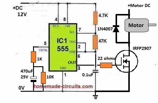
The 470uF capacitor determines the slow start length.
Sir, this circuit is not effective. It reduces all parameters such as rotation speed, starting current, and current consumption. total reduction. Just like reducing the power supply voltage to the motor. Maybe I should try a 2 ic 555 circuit?
LongE, How did you test the circuit?
First you should test without adding the capacitor between pin#5 and ground, just by using the pot.
If still it doesn’t work then your IC or your circuit might have some problems, because adding a pot with pin#5 of the IC should certainly allow the output PWMs to vary accordingly.
great article, very useful, simple and easily explained for less experienced people, I am a passionate electronics beginner and I would like to build a mechanism for roller blinds using a triac, but the motor must be able to rotate in both CW/CCW directions. Using your first one, it turns in one direction, and connect the second triac to control the second one.
Thanks for liking the concept, is your motor an AC motor or DC motor?
If it is a DC motor then transistors can be used for flipping the polarity.
Hello
How nice that you replied so quickly 🙂 great 🙂 it’s an AC TYJ50-8A7 CW/CCW motor and I want to use it to roll up and unwind the blinds
Thanks kris, Ok got it, however PWM cannot be effectively used for AC motors with triacs, so that’s the problem…
Hello Swagatam. Great article and thanks for your insights!.
I need your help with a soft starter diagram for a 8.4V DC motor. According to the above configuration, I do not have a 2.7v zenner diode. I only have 5.1v and 12v types. Regarding transistor BC557, BC547, I have C1815, A1015, how should I fix it? Is it possible that the 2s 18650 8.4V battery is enough to fully power the motor when reaching max speed?.Thank sir.
Thank you LongE,
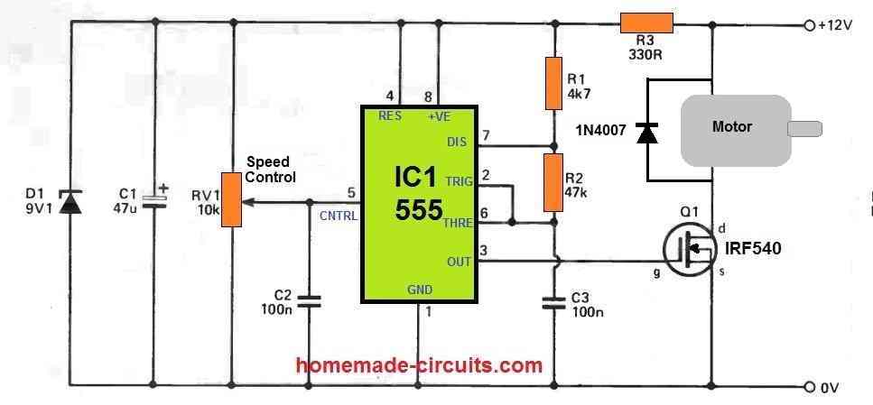
Instead of the above concepts, I would recommend you to first try the following simple design:
In this design just replace the C2 capacitor with a 100uF or a 220uF for generating the soft start.
Furthermore, you can replace the MOSFET with a BJT if required, depending on the current rating of your motor.
2s 18650 8.4V battery should be enough for generating max speed on your motor, assuming the motor current rating is within the battery’s max current delivering capacity….
Thank you sir, So I will change C2 to 220uF and remove D1 Z9,1v ; R3 330 ohms. The no-load starting current of this RS540 motor is 10 Amp and reaches stability at 6 Amp. In my opinion, BJT cannot be used. I’ll try assembling the circuit over the weekend.
No problem LongE, please go ahead, and let me know how it goes…
I would like to use this assembly for my pump, 220 volt 1.5 Ph
Sure, You can try it….
Bro just asking, but can you help make a circuit? a pwm motor speed controller with the soft start?
I’m running 775 and 590 motors but the ones from market lebeled as pwm controller doesn’t seem to like work. when I turn the pot from 0, there’s always a twisting jerk in the motors. i want to eliminate that, and run the motor smoothly.
Sure Bro, I will try to design it for you, please let me know if your motors are AC motors and DC motors?? Then I will configure the circuit accordingly..
No it’s simple dc motor but high power.
Talking about johnson 775 and divyanshi 590 dc motor
OK, then I think you can try the following concept. Just increase the C2 value to 100uF to get a soft start at the start:
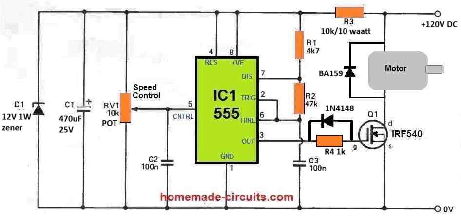
can it handle 24v 20 amp dc?
as my motors are rated for 7 amp minimum when i bought it.
that 12vdc-24vdc , minimum 7 amp, so under load and some upper margin, 20 amp capable I wanna make it
Yes, IRF540 can handle 24V 20 amp load…if possible please add a snubber also across the MOSFET…
https://www.homemade-circuits.com/rc-snubber-calculator-for-mosfets-relay-contacts-and-triacs/
thank for the suggestion. you are my big bro in my hobby. you really are so helpful 😊🙏
No problem Bivash, you are most welcome…
and where do I use mod for direction change? for, forward reverse rotation
If you want a bidirectional motor control then you may have to go for a dedicated H-bridge driver circuit, such as this one:
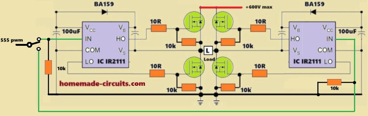
The diagram that you emailed me will unfortunately not work…