Voltage stabilizer in the range of kVAs are powerful AC voltage stabilizer units specially designed for controlling and stabilizing high voltage fluctuations, for high power electrical equipment.
In this article I have explained an easy to build a 7 stage high wattage in the order of 5000 to 1000 watts stabilizer circuit which can be used for controlling our mains AC line fluctuations and for producing very accurate stabilized voltage outputs for our domestic electrical appliances.
Circuit Operation
The proposed Accurate 7 relay OpAmp Controlled Mains Voltage Stabilizer Circuit concept is rather very simple. It uses discrete opamps wired up as comparators to sense the voltage levels.
As can be seen in the diagram, each opamp's inverting inputs are provided with sequentially incrementing voltage reference levels through a series of presets which drops a certain amount of voltage across itself.
Each opamp compares this voltage with the common sample mains AC voltage level supplied to the opamps non inverting inputs.
As long as this sample voltage is below the reference level the respective opamps keep their outputs low and the subsequent transistor relay stages remain inactive, however in case the voltage levels tends to shift from its normal range, the relevant relays trigger and toggle the transformer taps so that the output is appropriately equalized and corrected.
For example if the input AC voltage tends to fall, the upper relays may get triggered connecting the relevant higher voltage taps with the output and vice versa in case the voltage shoots upwards.
Here the opamp output inter-connections makes sure that only one optocoupler and therefore only one relay gets activated at a time.
Parts List
- P1---P8 = 10 K Preset,
- A1---A8 = IC 324 (2 Nos)
- R1---R8 = 1 K,
- All diodes = 1N4007,
- All relays = 12 volts, 400 Ohms, SPDT,
- Opto Couplers are all = MCT2E or equivalent,
Transformer = Pink Tap is normal voltage tap, the upper taps are in the decrementing order of 25 Volts, while the lower taps are in the incremental order of 25 volts.
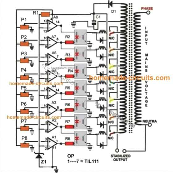
Full circuit diagram of the proposed Accurate 7-Stage OpAmp Controlled Mains Voltage Stabilizer.
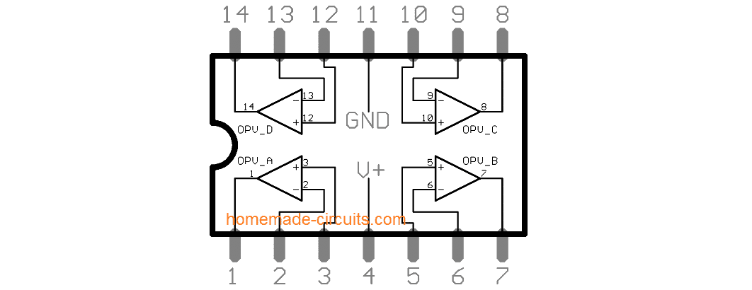
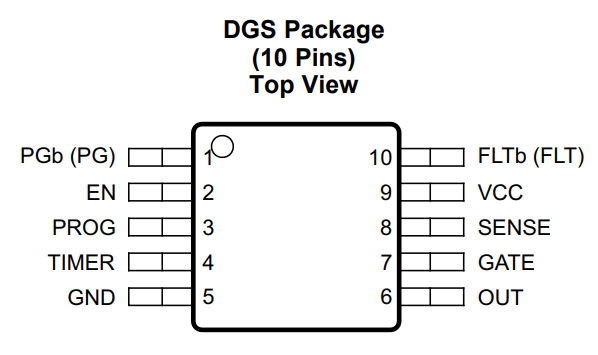
IC LM324 Pinout Details
Circuit Diagram
Upgrading into a Solid State Version using SSR
The diagram below shows a rather simple voltage stabilizer design which can hold huge output power in the range of 5 to 10KVA. The use of SSR or solid state relays makes the output stage easy to configure and very accurate - thanks to the modern SSRs which are designed to trigger massive power in response to smaller input DC potentials.
Circuit Description
The proposed circuit of a simple high capacity automatic voltage stabilizer circuit is easy to understand. All the opamps are arranged in standard voltage comparator modes.
The presets P1 to P7 can be adjusted as per the required tripping points, which will correspond to the output SSR switching and the subsequent transformer tap selections.
The central green TAP is the normal voltage output, the lower TAPs gradually produce higher voltages while the upper TAPs are set for lower voltages.
These TAPs are chosen by the appropriate SSRs in response to the varying AC voltages, thus adjusting the output voltage to the appliances close to normal levels.
This circuit was asked by Mr. Alexandar and the SSR data was provided by him.
Parts List
- R1 to R9 = 1K, 1/4 watt,
- R10 = 10k 1/4 watt
- P1 to P8 = 10K preset,
- C1 = 1000uF/25V
- VR1 = 10K Preset,
- opamps = IC 324,
Transformer = Input 230volts or 120volts, Taps - incrementing/decrementing voltage levels (TAPs) as per individual specs.
SSR = 10KVA/230volts = output, 5 to 32 volts DC = input
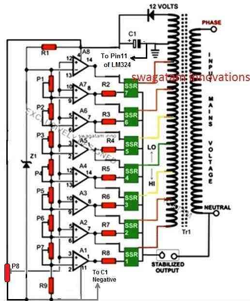
Full circuit diagram of the proposed A Simple 5 KVA to 10 KVA Automatic Voltage Stabilizer Circuit @220 Volts, 120 Volts
Solid State SSR Voltage Stabilizer Circuit Diagram
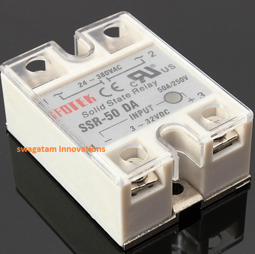
SSR Image

Questions & Answers
Hello Mr. Swagatham, I tried the SSR stabilizer. When I increased the voltage quickly, all the triacs exploded. Can you tell me a way to prevent the triac from exploding? Also, I had used a snubber in the circuit. I would appreciate your guidance. Thank you.
Hi Alo,
If your SSR is getting burnt, it can be due to only one reason, the transformer is not wired correctly and the SSR triacs are getting shorted. Please try with a single winding auto-transformer.
Also please use 3V zener diode in series with each of the outputs of the opamp, for enhanced deadtime and safety.
hi sir have a good day, i was trying to replicate one of your circuits that uses cd4093 but could not implement it on a single sided board, because there just too many of the diode needed when using three ic. so i came across this circuit that uses lm324 and prototyped it on board using single ic and three led as switching and it seems to work for three varying dc voltages, i’ve noticed though that P4 and P3 both control a single Led and second Led is controlled by P2 and third Led by P1. And i’ve used three different batterries since i don’t have a variable power supply, which giving me varying light intensity. i’m actually planning to use it on a multi tapped step transformer. could i lowered down the resistor on output of the lowest ac input to have good light intensity? thanks in advance
Hi Alinader, Each preset will be responsible for toggling the corresponding upper and lower LEDs of the opto.
Yes, you can adjust the opamp output resistor values for getting optimum brightness on the LEDs.
Good day Mr.Swagatam, please in the four step monster power whole house Automatic voltage stabilizer, I notice that, the circuit biasing voltage was taking from a small voltage from the autotransformer winding directly which was rectified with a diode and fed to point B on the circuit.
But, I think the circuit will be live voltage f=from the mains, though DC voltage and could be dangerous.
Can we do a step down transformer to the auto transformer to be controlling the circuit?. Could be a 12volts or 15volts to power the the circuit,
Yout thought is needed as soon as possible.
Thank you sir
The voltage that is fed to the ICs are maybe of 12v. as you can see it got out of the transformer after a very small amount of winding which indicates that it is a low voltage.
pls i need a simple diagram of 5kva automatic voltage regulator not SSR that can power my 1.5HP borehole pump. The voltage should pick from 100v AC supply. Thanks
For this you will need a 6kva transformer, would you be able to afford that?
Good day boss, I can afford the 6kva transformer
Ok great, but if you do not want to use SSR, then do you want to use relays? please let me know.
Sir,
Can I use the above circuit for 1kva stabiliser?
If possible please how?
You can use it for any desired load, by upgrading the relay and the transformer specs appropriately.
Hi there,
Does your circuit require/benefit from an isolation transformer in case of failure?
The transformer used in this design is an auto transformer, it does not have an isolation.
A very informative and practical site for hobbyists. Was going through it for stable power supply ideas and some ideas are really useful. Please make a project (with principles explained) on IGBT based PWM controlled static voltage stabilizer (220 v stable output) for connecting to main home supply (5-10 KVA). Eagerly waiting for the same.
Thank you, and glad you liked the post. I will try to figure the concept you have suggested, and if it’s possible I would surely post the same in this blog.
Ing very grateful for your information I have the pcb but I need the 4-step stabilizer diagram with the cd4093 to know where each component goes. Thank you. Help me. Thank you.
No problem, you can refer to the following post for more info:
https://www.homemade-circuits.com/build-solid-state-scrtriac-controlled/
Swag, all right?
Thanks for your return.
I designed the entire circuit in a simulation software, but the control of the outputs in the trimpots is difficult, while the regulation of each one alters the other.
I designed a 220v transformer, first tape to power the circuit in 12v, tape 02 – 170v – tape 03 – 180v and so on until the final tape of 230v.
Do you have any tips to improve the situation?
I even tried to separate the trimpots so that there is individual voltage correction, but without success, thanks again.
Thank you Lucca, for updating the results.
Only two subsequent opamps will react with each other at a given instant, and this will happen sequentially depending upon the setting of the presets. The presets must be set so that the transitions happen sequentially. Also, only one opamp can be high at any given instant that makes the design quite foolproof.
You can probably try replacing the presets with calculated resistors with incrementing values so that the transitions are sharp and perfectly sequential in response to the voltage fluctuations.
One example using fixed resistors can be seen in the following article:
https://www.homemade-circuits.com/4-led-temperature-indicator-circuit/
Hello how are you? I found the project very interesting and I’m trying to build it. I made a test transformer with 8 tapes, input can vary from 150 to 230v, the tapes correct at 220+-3%, but I’m having some difficulties in the circuit. if i can send me an email so we can exchange ideas.
Hello, thank you and I appreciate your efforts in building this circuit, however troubleshooting a ferrite based inverter can be very difficult without analyzing it practically. Still I will try to help you as much as possible, you can ask your questions here.
Thanks for the feedback.
Is this transformer a ferrite or silicon core?
Iron core transformer.
Swag, Alright?
Where is the R10 located on the circuit?
Did you simulate this circuit in any program? If possible give feedback.
Hello Lucca,
You an ignore, it was probably present in one of the previous diagrams which was modified with the existing ones.
I have simulated these circuits with my knowledge and understanding and according to me there’s no way it cannot work….
I can’t comment on simulators since I never use them
hello Swag, in the above diagram, the value of zeiner diode z1 is not mentioned. what is the value sir.
Hello Olusegun, Z1 can be any value between 3V and 9V, for the reference voltage.
Hi Swag! I have a 10kva , 2 phase stabilier , which has magnetic relays (3 No’s.). The load current required is about 30 amps max. The transformer is step down type. Now I wish to replace the whole circuit with SSR based circuit. Could you please be kind enough to guide me providing the details.
Hi RP, I could not find any SSR having N/O and N/C contacts both, so I am not sure how it can replaced with a relay!
This could be thing maybe i waiting for, i am not a geek but tinker a bit,
i have a 7.5Kv manual voltage stabiliser, using for audio dj amplifier, but when there is sudden voltage swing blew the amp, hence want it MADE TO automatic voltage stabiliser- relay based, i have check the micro controller circuit online but it has only 4+1 relay out, in my manual stabiliser have 8 steps, so your CIRCUIT MAY DO? pls do communicate on my mail jj2apps@gmail.com
Glad you found the article useful. You can definitely give it is try, however the circuit being quite complex is actually not recommended for the newcomers.
thank you Swagatam for replying so quickly, never expected it! , i am interested in the ready microcontroller working kit. relay will buy locally. pls suggest
You are welcome John, however I do not have a microcontroller based circuit with me at this moment. Possibly, I may try to find it and post it in the above article soon
Circuit? No pls, complete board n tested. Need only buy relays. Thanks, if possible, do reply
OK, if I find an appropriate source, will let you know!
I adjusted my factory made stabiliser to lower the output voltage but now I want to readjust as before for high output voltage but couldn’t get it. Please Swag, assist Sir
Seun, without seeing the board it can be difficult to know which presets need to be adjusted and why they may not be working…
yes. that looks much better! lol
There is possibly a resistor missing from the bottom of VR1 to ground in my opinion since there is no voltage divider effect created by VR1 other than with the load to ground formed by the parallel inputs of the 8 op amps +input pins. VR1 is only 1K so a much lower resistor value than that of the 8 parallel +ve input pins would be required. I seriously doubt that this design will work without it since the zener is 6 v, the -ve inputs are between about 5.5 and 0.8 volt while the +ve inputs will be up at about 15v. Perhaps VR1 around 20k and the resistor to ground from it around 10K? R9 seems low at 1k as well. The taps should not be 25 volts apart. They should only be about 10 volts apart unless you live in an area with extraordinarily poor quality power!
Where i live being able to regulate mains inputs like 260 250 240 230 220 210 200 190 to the output you want such as 220 or 230 would be correct and the taps on the extreme ends would never be used. If you live in a rural area with a very long transmission line and extreme voltage drop you may need 15 v taps but it’s hard to see anywhere you would want 200 volts variance (8 times 25) as your range. The trimpots have to be adjusted so there is overlap and NEVER a state where all outputs are off unless Vin is very low and you want brownout protection. I would try : increase R9, add the resistor i mentioned, alter VR1 and lower the tap voltage. A couple of 0.1 uf ceramics from pins 4 and 12 to ground wouldn’t hurt either To bypass spikes and RF noise and protect the I.C. The transformer should have an overheating cutout in it to disconnect the whole thing so it can’t cause a fire in the event of malfunction such as two shorted ssr’s shorting the windings.
i think you are looking at the wrong diagram. VR1 and the SSR’s dont exist on the first version. Im clearly looking at the second version so perhaps look again at my comments
Yes, the VR1 in the second diagram needed a correction, I have changed its name and configuration accordingly.
The preset itself is very much capable of providing a voltage divider effect right between 0 and the max supply voltage. Remember the op amp inputs are high impedance inputs so it really doesn’t mater whether you are using a 1k or a 10k, or a 100k. It is the ratio of resistance between the slider/positive and the slider/negative that matters.
You can add resistors at the positive side and negative side of the presets to squeeze the window of the adjustments, to make the adjustments a little easier, although that is not necessary.
Capacitors can be added across as many nodes as possible to protect against any form of spikes or transients…
Hi sir.
Please help me with the new generation Stabilizer.
igbt based voltage stabilizer
Hi Amin, I do not have this circuit with me at this moment, but if I find I will post it for you….
Please provide a circuit for 220VAC and 110VAC stabilizer having an auto transformer with taping of 94V, 109V,127V, 148V, 171V, 199V, 215V, 231V with relays.
You can try the first circuit from the above article and customize the relay contacts as per the tappings of your transformer.