In this post I have explained a few innovating and simple soft start circuit examples which may be implemented with heavy duty motors so that they are able to initiate with a soft start or a slow sluggish start instead of a sudden, bumpy start
Why Soft Start is Crucial for Heavy Motors
When heavy motor systems or high current motors are involved, initial switch ON current surge often becomes an issue. This surge tends to inflict huge arcing across the pump relay contacts causing corrosion and reduction in its life due to stress, and wear and tear.
The high current arcing not only causes relay contact issues, but also affects surrounding electronic circuits, causing them to hang or get disturbed due to large amount of RF interference generated during motor switch ON.
However safeguarding the costly motor relay becomes the main issue with such situations. Though there are many mechanical contactors available for controlling motor stress, these system are not efficient and are ineffective against the RF emissions.
The simple electronic circuit presented below hopefully is able to eliminate all issues concerned with heavy motor switch ON surge generation and relay contact protection.
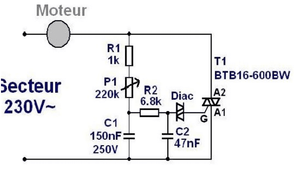
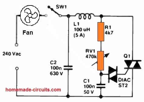
The figure shows a simple dimmer switch circuit incorporating an ordinary triac and diac configuration, which can be very effectively used for adding a soft start to any high current, heavy AC motor.
Designing a Soft Start using Triac Phase Chopping
Here the control pot has been replaced with a LED/LDR box. As we know that in normal dimmer switches, a variable resistance is used for controlling the fan speeds. Here the variable resistance is replaced with a LED/LDR arrangement. It means now the speed of the motor, or in other words, current to the motor can be controlled by controlling the intensity of the enclosed LED through an external trigger.
That's exactly what is done here. When the motor relay is switched ON, either by a switch or through an electronic control circuit such as a water level controller circuit, the LED of the attached dimmer switch is also switched ON simultaneously.
The LED switches ON the triac and the connected motor.
Being a solid state device the dimmer switch acts a little faster than the relay and therefore the motor is first activated through the dimmer triac and just after a few milliseconds the triac gets bypassed by the concerned relay contacts.
The above process completely eliminates any sparking from the relay contact since the triac has already absorbed much of the current and the relay only has to softly takeover the already switched ON motor conduction.
Here the brightness of the opto-coupler LED is crucial, and must be set such that the triac is only 75% ON.
This adjustment will save the triac from initial heavy current transient and help the entire system to last for many many years.
The resistor R4 may be appropriately set for achieving an optimal glow over the LED.
Circuit Diagram
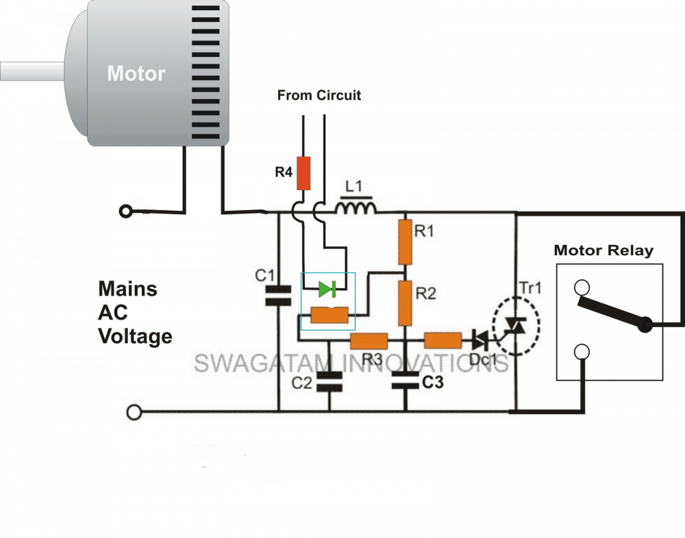
Parts List
R1 = 15K
R2 = 330K,
R3 = 10K,
Diac resistor = 100 Ohms,
R4 = to be adjusted as explained,
C1 = 0.1uF/400V
C2, C3 = 0.1uF/250V,
L1 = 10 amp/220V choke
Triac (Alternistor) = 10 Amp 400V,
Diac = as per the above triac.
Upgrading Triac Soft Start with Relay
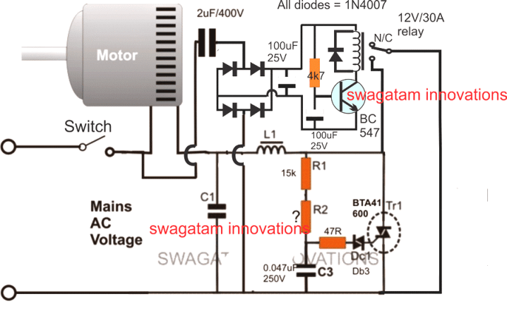
A little inspection reveals that the circuit actually does not require the opto coupler circuit at all. The circuit may be simply arranged in the following manner:
R2 should be selected such that the triac conducts only 75% of the power.
When power is switched ON, the triac provides a soft initial start to the motor until within the next split second when the relay also conducts enabling the motor the required full power. This completely safeguards the actuator contacts from the initial current surges and sparks,
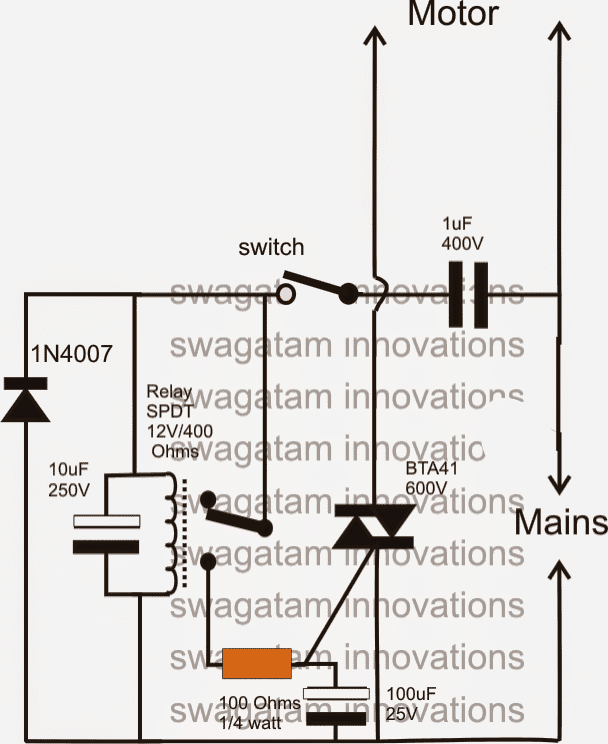
Simplified Soft Start Design
As rightly suggested by Mr.Jim, an initial torque is imperative for initiating a motor optimally especially when it's loaded, if this initial torque is absent. the motor might stall with heavy loads under its belt and might start smoking within minutes.
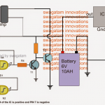
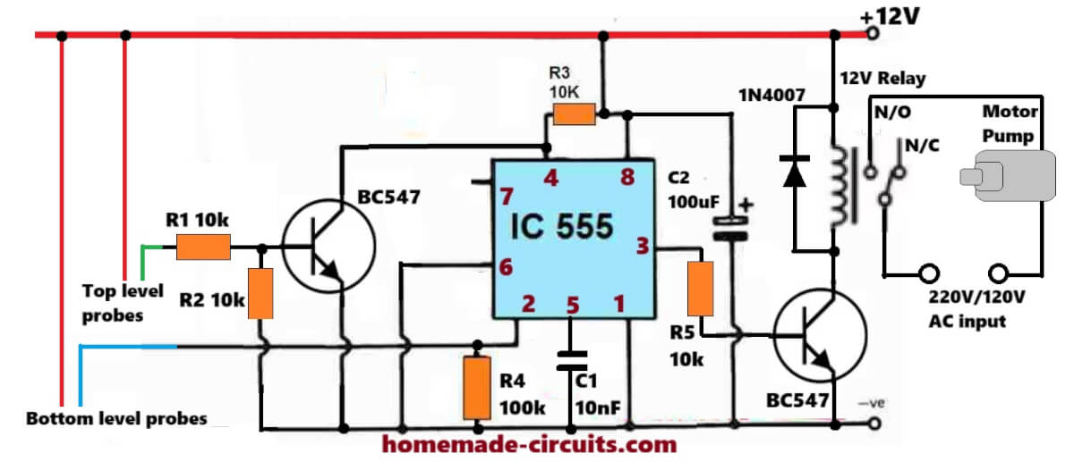
The following circuit is designed for solving both the issues together, it inhibits the initial surge current to the ON/OFF switch and yet allows the motor to start with a "kick" so that it initiates without problems even when it's loaded.
The above design can be even further simplified by removing the relay, as shown below:
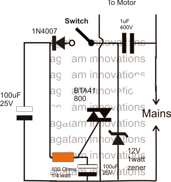
An technicallu more sound PWM based motor soft start circuit can also be tried for getting a better control, a better torque and a reliable startup for the connected motor, even for 3 phase motors.
Soft Start Using Controlled Phase Chopping
Another way of implementing triacs through stepped phase chopping, for initiating slow soft start and slow end or slow stop circuit for heavy machine motors so that the motors are able to go through a gradually start stop actions instead of switching ON/OFF abruptly.
The idea is basically intended to ensure less wear and tear on the motor and additionally save electricity during the course of actions.
The idea was requested by Mr. Bernard Botte.
Dear mister Swagatam,
Sorry for my English , thanks anyway for any answer you will give Before the question. I use different apparatus to handle wood using universal AC motor originally made for a range between 230 to 240 volt 50hz (but I notice in certain part of my country 250V too) because I need a lot off different kind of machine and that was only for hobby.
I buy the cheapest machines I can find (I correct certain mechanical problems) for other machines. I use also a dimmer (home made based on the system used by vacuum cleaner and modified byNINA67 ) and It work great.
The motor run at +/- 18000 : 3 =6000 !!! Knowing the cheap cost of that machine I use it like a “good father” not intensively etcBut one day there was a fume
The machine smoke and i dismount the machine to isolate the motor to evict the fire . (the machine was under warranty but i need to make a lot off kilometers to make an exchange. And there, they don’t tell me it was a well known and reccurent problem … but … they know it! )
In fact when everything was cold . I look the axis who rotate he seems also shooting on the opposite side of the gear belt at every start Like there wasn’t a grower.
I show the motor in a company saling different kind of motor.
They make also refurbishing but they explain to me that it was an “exotic” motor but they set the same diagnostic .Start to fast So come my question: Could you please make a schematic to have a “soft start / soft ending ” for different universalmotors in fact if i use my dimmer system based on BTA 16 800 cw (better than the other mentioned above) it seems ok but i have only made 3 of them . I’ll want to integrate that in every big machine .
And use only the on/off switch.I want use thus a button to “switch on” and one to “switch off” or an on/off switch.
But also a potentiometer to select the minimum level (depending the power of each motors) when the motor start running and a potentiometer to select the timing (555) between the slow start and the full speed (maybe also shortcut the triac with a relay to have full speed an a green led if it is relevant (but it will be nice) for the switch off the timing maybe reduce. Why at the end because the extra current and problems binded.
Note : I have seen this application with “fpla” or dedicated processors but I am sure it can also be done with discrete components.Why i can not do that : because I never study the motors correctly but I know for example that it is not correct to start the motor with a zero crossing system because It give a maximum current and that make the same trouble (FIRE!) with the couple at start and max current …
I have seen this request in other forum touching other job mechanic wood etc … with no answer and people say also if it work with a potentiometer but when you change from a machine to another you can make mistakes etc…Regards Botte Bernard (Belgium)please don’t put my adress on the net Nb i like also in your presentation the datasheet because it’s no so easy to have it without paying
Bernard Botte
Designing the Stepped Phase Control Circuit
The requested idea of a soft start, soft stop motor switching circuit can be implemented using a simple triac based dimmer switch concept, as presented in the following diagrams:
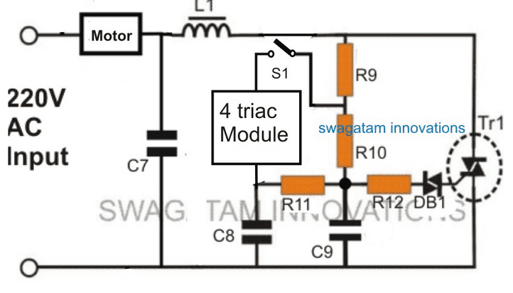
Referring to the above diagrams, the first diagram shows a standard light dimmer or a fan dimmer switch circuit using a heavy duty triac BTA41A/600.
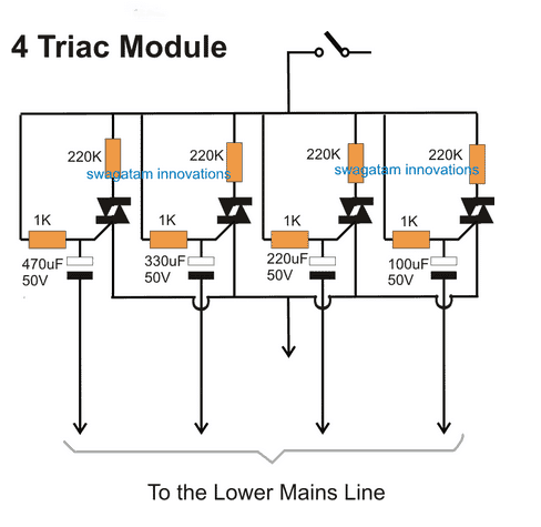
The section which indicates the “4 triac module” is normally occupied with a potentiometer for enabling a manual speed control adjustment, wherein a lower resistance adjustment generates higher speed on the fan motor and vice versa. In this soft start, soft stop design, this pot section is replaced with the indicated 4 triac module which can be elaborately visualized in the second diagram.
Here we see 4 triacs arranged in parallel having 4 individual 220K resistors at their upper MT1 arm, and 4 individual capacitors at their gates with different values, and with a sort of sequential order of high to low. When S1 is switched ON, the triac having the lowest value capacitor switches ON first, enabling a relatively slow speed start on the motor due to switching of the relevant 220K resistor at its MT1.
Within a few millseconds the next subsequent triac conducts which has the next smaller value, and adds its own 220K resistor in parallel with the earlier 220K resistor, allowing the motor to gain some more speed. Identically, the third and the fourth triacs also sequentially switch ON within the next few milliseconds, thereby adding two more 220K parallel resistors in the range, which finally allows the motor to reach its maximum speed.
The above sequential speed increase on the motor allows the motor to achieve the intended slow start switch ON, as desired by the user.
Quite similarly when the switch S1 is turned OFF, the relevant capacitors switch OFF in the same order but in a descending manner, which inhibits the motor from a sudden stop, instead it causes a step wise slow stop or slow end on its speed.
Feedback from Mr. Bernard:
Dear mister Swag, First of all, thanks for your fast answer. Because you tell me you have a timing problem I have changed my operating system to linux mint 18,1 ‘Serena’ so i haved to re-install all the program I need and test it (setup it!) So apparently everithings seems working OK ! About the first schematic I notice you don’t give any value to the upper side schematics so I pick it up from « How to Make a Simplest Triac Dimmer Switch Circuit »
Parts List for the above enhanced fan dimmer circuit(C1) C7 = 0.1u/400V
(C2, C3) C8,C9 = 0.022/250V,
(R1) R9 = 15K,
(R2) R10 = 330K,
(R3) R11 = 33K,
(R4) R12 = 100 Ohms,VR1 = 220K, or 470K linear => Replaced by genial 4 triacs module
Diac = DB3,
Triac = BT136 => BTA41 600
L1 = 40uH
About the second schematic so simple solution i never have dreamed !!! to be tested asap Genial! we say in French.
I doesn’t know that you can use polarized condensators for such AC applications! And also that 50 volt was sufficient! I you have a moment to explain why -
Anyway maybe i’ll try it this weekend if i have all the component. I prefer use new capacitors my stock never change since 1993!
In fact i was trying different ways using for example opto triac (MOC) but i also need to pick the freq of the AC network, also another based on your schematic Kiln Temperature Controller Circuit but with up down counter 4516b and 555 etc,etc so complicated
Many thanks
Regards
B.botte
My Response:
Thanks dear Bernard,
The image which you had inserted in the conversation did not get attached properly and therefore it was not showing, but I have corrected it now and have posted it back in the article.
I have rated the caps at 50V because R9 is supposed to be a 33K or a 68K resistor which will drop the current significantly and not allow the capacitors to burn, this is my understanding.
I have used polarized capacitors because the gate of a triac works with a DC drive, but yes you are right, in order to make it DC for the capacitors we need to add a 1N4007 in series with the gate 1K resistors.
Now with regards to this design, if suppose the idea does not operate very smoothly or fails to produce the expected results, we could modify the existing gate drive for the 4 triacs into optocoupler based drivers, and perform the same sequential delayed switching but through an external DC circuit.So this circuit ultimately has the potentials to deliver the intended results, either this way or that way.Regards Swag

Questions & Answers
Hello Mr. Swagatam
How can I use a soft starter 4 triac circuit for three-phase power?
Thank you very much for your kind help.
Hi Muller, sorry, I have no idea how the 4 triac circuit can be customized for a 3 phase version…
Good Day
I have a 2,2kw single phase motor that drives a comprssor. As I have a inverter at home the inrush current keeps tripping the inverter.Will your circuit work with a 2,2kw motor
Thanks Gary
Hi Thanks for the information,just two questions.
1 What does the coil R1 do as I do not see its contacts
2 how do I work out R2
sorry I am not an expert on electronic circuits
Gary
Coil L1 and C1 are there to suppress external noise transmission. Since the slow start operation is supposed to be only for a few seconds, you can eliminate the L1, C1 parts.
You can start R2 with a 100k resistor and replace the motor with a incandescent 100 watt bulb, and check the brightness. It should around 70% of it total brightness, if not then adjust the 100k R2 value until an approximately 60 to 70% brightness is achieved…during this time keep the relay section disconnected.
Yes, the above circuits will work to solve your problem, if the compressor motor is a capacitor start type motor.

I would recommend the following design: Make sure to select R2 appropriately…
YES I HAVE ALREADY ASSEMBLED THE 2 CIRCUITS AND THEY WORK
https://www.homemade-circuits.com/how-to-make-simplest-triac-flasher/
https://www.homemade-circuits.com/simple-ceiling-fan-regulator-circuit/
but with the SAME PROBLEMS = VARIATION of VOLTAGE at the OUTPUT
according to the VARIATION of the VOLTAGE of the MAINS at the INPUT
IT DOES NOT STABILIZE at 35v
this
is the same as this one with minimal changes

and I CANNOT USE POTENTIOMETER
SEVERAL PEOPLE WITHOUT SCHOOLING USE THE MACHINE
LOW INCOME COMMUNITIES = RECYCLING CENTER
so REMEMBERING the VARIATION of the ELECTRICITY GRID
110v varies between 107v to 127v
220v varies between 212v to 232v
how to ADD a ZENER or SOMETHING SIMILAR

to FIX at 35v at the OUTPUT in these 2 CIRCUITS
No, these two diagrams are not the same…they are completely different.
In an AC dimmer circuit, if the input voltage changes then the output AC will also change it cannot be controlled with a zener diode.
If the 35V is DC then it can be stabilized to a fixed 35V…
in the PREVIOUS QUESTIONS
I am always making a REFERENCE of 35v OUTPUT also in ALTERNATING CURRENT
that is, a SIMPLE DIMMER with STABILIZED OUTPUT
in BRAZIL TRANSFORMERS are things from the MOVIE JURASIC PARK
If you want a AC dimmer circuit, you can try one of the designs from the following articles:
https://www.homemade-circuits.com/how-to-make-simplest-triac-flasher/
https://www.homemade-circuits.com/simple-ceiling-fan-regulator-circuit/
very bad google translation
or you didn’t understand my question
this is nothing more than a DIMMER
with ZENNER to keep it at 12v
1-how to ADD a 110/220v SWITCH in this same circuit and which components to add/change???
2-if you CHANGE the ZENER to 35v will the OUTPUT also be FIXED at 35v???
Thanks again
It is not a dimmer circuit, it is soft-start Triac switch with delay circuit.
The circuit will work for both 120V and 220V inputs so need of any switch.
The zener diode has nothing to do with the output voltage, it is just for stabilizing and rectifying the triac gate voltage.
Hi Mr. Swagatam
my English is very bad
(text written in Google Translate)
Here in BRAZIL the ELECTRICITY GRID is a BIG GARBAGE
110v varies between 107v to 127v
220v varies between 212v to 232v
I use a MACHINE that has a WIRE RESISTANCE
(shower type) 35v 300w
with the VARIATION of the GRID this RESISTANCE BURN OUT of nowhere
in this SIMPLE CIRCUIT

is it possible to ADD a 110/220v SWITCH
or make this GRID CHANGE AUTOMATIC???
and the ZENER can LIMIT=FIX the VOLTAGE OUTPUT at up to 35v
even with the VARIATION of the ELECTRICITY GRID
if you can SHOW the COMPLETE CIRCUIT in an IMAGE I would appreciate it
my electronics are basic / just circuit assembly
and component replacement
Thank you for your attention
LUIS BUENO
99% RECYCLED-Brazil
Hi Luis,
A 35V load will certainly burn if it is used with a supply of 110V or 220V, so you must operate it with a regulated supply of 35V only.
If you use a 35V supply then no changeover or surge control circuit would be required.
However to convert a 110V or 220V to 35V 300W you would require a large transformer.
Let me know if you can procure this transformer…
In the Option 2, can I add an MCU switching option at the 47Ohm resistor with an optocoupler like PC817. Then, the Switch to the motor will close for all time. By allow current at the resistor (47Ohm), the BTA41 will be triggered.
I am thinking of this to make a compact SoftStarter for the single phase submersible pump so it can be controlled via ESP32. Also, I dont see RC snubber in the option.
Please advise with thanks!
An MCU might not work since it cannot control the triac with a 75% or 50% power output.
Only a triac dimmer setup as shown in the diagram can be used to implement the above.
You can add an RC snubber to the triac, or use a triac which has an in-built snubber circuit.
Hi Swagatam,
I have made a dimmer Using BTA41 with H11AA as the ZCD using the option 2 controlled by an ESP8266 promin D1. I also have a dedicated Soft starter (a Chinese brand) at hand using SSR. What I am wondering is: the Chinese one have functions to delay the starting up in xx seconds (means at the end of that time range, the voltage will ramp up to the full voltage from the beginning set level . i.e 50% of main voltage). So far as I understood, using triac mean cut off power provided to the pump at some segment from zero cross point and increase the duty cycle along the progress of the defined time. Does it mean the Chinese soft starter will do the same?
The reason I am asking is whether it would be okay for using the dimmer approach (typically the same as option 2) to control the soft starting up of the submersible pump using Esp32/8266? I knew that dimmer can not be used with regular AC fans but for light deeming only.
Best regards
Hi Dang,
I guess you are referring to the Design#1 from the above article, which incorporates a PWM approach through an opto-coupler?
Yes, your assumptions are correct regarding the soft-start using a controlled duty cycle. The Chinese circuit could also be doing the same.
If you are using Design#2 then the opto coupler is not required and it cannot be interfaced with an MCU.
The first circuit can be interfaced with a PWM MCU or any ramping PWM source.
An AC dimmer is specifically intended to be used with regular AC fans, provided they are capacitor-start type and not BLDC.
I’ve just joined your site today.
I’m keen to build the circuit with four triacs. I’ve purchased the components required to build this circuit.
I’m just unclear on some details. In the second diagram it shows four arrows pointing down and says “To the lower mains line.” There’s a shorter arrow pointing down in the middle of the four longer arrows. Where is this supposed to connect to?
Also, does the switch to start this circuit need to be a 10 amp?
And in the first diagram it shows a circle around Tr1. Does this signify anything?
Thanks.
Hi, sure, you can try it, but please be aware that the design is based on my assumptions only, so i am not confident whether it will work or not.
The short arrow will go to the junction of R11, C8.
The longer arrows will go to the bottom common line which connects with C8, C9.
The switch can be a 1 amp switch, that’s enough.
The circle indicates that the triac Tr1 might need a heatsink, depending on the load power spec.
Ten months since I placed my first comment. It’s taken me this long to get around to finishing building this circuit, based on your schematic above.
I fired it up today, and nothing at all happens. I’ve connected the circuit to a small motor out of a fan heater. The motor works fine without the circuit. I’ll go through all of my connections to look for faults.
I read above the following:
“I have used polarized capacitors because the gate of a triac works with a DC drive, but yes you are right, in order to make it DC for the capacitors we need to add a 1N4007 in series with the gate 1K resistors.”
I didn’t follow this part as they weren’t included within the circuit diagram. Do I need to re-do the whole triac module with four 1N4007 diodes?
Many thanks!
Initially, can you please remove the 4 triac module entirely and replace it with a pot as shown below, and check whether moving the pot varies the motor speed or not?

That’s not the circuit I built. It’s this one, and the four triac module.
Yes, the pot in the above circuit is replaced with the 4 triac module, so temporarily please remove the 4 triac module and replace it with a pot to check if the circuit works in the basic mode or not?
My bad. Upon doing some more continuity testing on my circuit board, I found that cap C7 was not connected to the motor and L1. Really silly of me to not notice that, but it’s all about learning.
There was another track I had found earlier also not connected.
After this latest “debug” the motor finally runs, but it runs without the switch going from between R9 and R10 being activated. I guess I’ll have to do some more checking of all my soldering joins. 🙂
OK, no problem!
R10 must be a high value resistor of around 330k or 470k. Did you use this?
Hi Swagatam, I’m still working my way through trouble-shooting the circuit I built. I haven’t tried using a potentiometer yet. I’ve copied the image of the first circuit and annotated the component values onto the image, to confirm I have used the correct ones. I’m confused about one of the components used. In the original image it says the Diac = DB1. However in the parts list is says DB3. Which is the correct one please?
Hi Stu,
DB3 is the correct one, and is easily available.
Let me know if you any further doubts or questions.
HI Swagatammy ? is i have deep well pump 120 voltscan i install a soft starer and if wher can i found them
thanks
Hi Mario,
You can add one of the above soft start circuits to your 120V deep well motor, however you will have to first build the circuit and verify its functioning on a workbench, I am not sure whether this circuit is available ready-made or not.
Hi Swagatam;
I found a motor P/N: KM-36F1-500 allegedly it is for the water meter purpose and it has mini gear box. Some sellers introduce it as 3 V and others do 12 V. The coil resistance is about 5 or 6 ohm. How I can decide on proper voltage? Best Regards
Hi Suat,
You can start from 3V and slowly increase the voltage and check at what voltage the motor starts warming up. If the motor starts warming up at a certain voltage level that will indicate a high voltage for the motor. You can reduce the voltage by 1V from that level to ensure the correct voltage for the motor.
Hello, I want to thank you for this article. I do need clarification on my specific situation. I have a 240V 60Hz submersible water well pump that I run with a 4000 Watt engine generator. The inrush is too great for the generator but I can turn the pump switch on and off rapidly to keep the generator from choking off until the pump starts spinning enough for the generator to handle the load. Obviously the turn solution is a larger generator but I think a slow start circuit may replicate what I am doing manually with the on/off switch and save me some money. My question is because this pump uses 2 hot wires plus neutral, do I replicate the slow start circuit on both of the hot legs or do I just need the one circuit?
Thanks for any help you can provide.
Hello, yes you can use two relays, or a single DPDT relay. However, you can also try 3 relays, meaning a relay for the neutral wire also, to make things entirely safe.
Hi Swagatam,
On Simplified Soft Start diagram above, the current run through the triac is only a few second before passed back by relay, for motor less than 1 HP, can I replace triac by an SCR? If so, any circuit change?
Thank You.
H Awak, I think that is possible. You can use any 300V, 8 amp SCR for the purpose. Use of SCR will allow a better slow start for the motor, since only the half AC cycles will be passed to the load thereby causing slower start for the load.
Thank a lot Swagatam, I will love this curcuit that will solve my water pump problem.
My pleasure Awak.
Hello,
I have 3hp 220V single phase motor for table saw.. currently starting with 40uf cap. for soft start from Q&A below I understand scheme 2 is best. as I have very little knowledge in electronics.. could you help –
1. what resistance should be R2?
2. what trigger voltage of diac?
3. will starting capacitor still be needed?
Thank you for a great and inspiring website!
Jonatan
Hello,
the starting capacitor is supposed to be a part of the motor, it is not associated with the dimmer circuit.
R2 will need to be experimented to find which value generates around 60% of speed on the motor without the relay assembly.
Hi I’m trying to find a suitable cct to enable a starter motor (on a classic Norton motorcycle) to soft start. It runs at 12v and 50A DC quite successfully but the mechanical system wears due to the shock load and a soft start would enable the system to cope better.
Many thanks
Hi, You can try the second design from the above article:
https://www.homemade-circuits.com/pwm-motor-soft-start-circuit/
If you can build it correctly it will do the job for your as intended.