In this post I have explained an effective PWM motor soft start circuit which can be used for enabling heavy motors with a soft start and thus prevent the equipment from drawing dangerous high currents.
Why a Soft Start
High wattage motors such pump motors or other forms of heavy industrial motors tend to draw huge current during their initial power switch ON, which in turn impacts the associated fuses and switches adversely causing these to either blow of or degrade overtime. In order to remedy the situation a soft start circuit becomes highly imperative.
In a few of my previous articles I have explained regarding a related topic, which you may learn comprehensively through the following posts:
Soft start circuit for pump motors
Soft start circuit for refrigerators
Although the above designs are quite useful, these may be considered slightly low tech with their approach.
In this article we'll see how the process may be implemented using a much sophisticated PWM based motor soft start controller circuit.
Using PWM Concept
The idea here is to apply a gradually incrementing PWM to a motor each time it's switched ON, this action allows the motor to attain a linearly increasing speed from zero to maximum within a stipulated period of time, which may be adjustable.
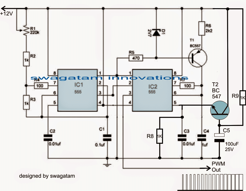
Note: Please use a Darlington BC547 configuration at pin#5 of IC2 instead of a single BC547. This will produce a more effective response compared to a single BC547
Example circuit for a variable 48V motor controller with soft start
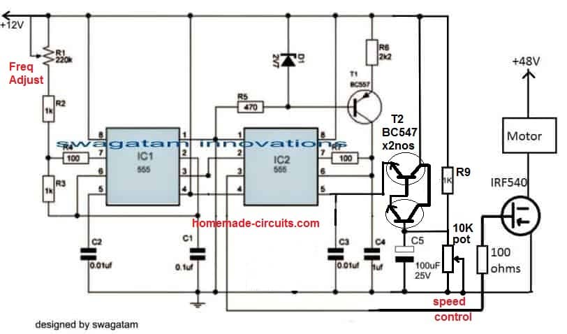
How it Works
Referring to the figure above, the production of the linearly incrementing PWM is achieved with the help of two 555 IC, configured in their standard PWM mode.
I have already discussed the concept elaborately in one of my earlier articles explaining how to use IC 555 for generating PWM.
As may be witnessed in the diagram, the configuration employs two 555 ICs, IC1 being wired like as astable, while IC2 as a comparator.
IC1 generates the required clock signals at a given frequency (determined by the values of R1 and C2) which is applied to pin#2 of the IC2.
IC2 utilizes the clock signal to generate triangle waves across its pin#7, so that these may be compared with the potential available at its control voltage pin#5.
Pin#5 acquires the required control voltage via an NPN emitter follower stage made with the help of T2 and the associated components.
When power is switched ON, T2 is fed with a ramping or a gradually increasing voltage at its base via R9, and due to the proportionate charging of C5.
This ramping potential is appropriately duplicated across the emitter of T2 with respect to the supply voltage at its collector, meaning the base data is converted into a gradually increasing potential ranging from zero to almost the supply voltage level.
This ramping voltage at pin#5 of IC 2 is instantly compared with available triangle wave across pin#7 of IC2, which is translated into a linearly incrementing PWM at pin#3 of IC2.
The linearly incrementing process of the PWMs goes on until C5 is fully charged and the base of T2 attains a stable voltage level.
The above design takes care of the PWM generation each time power is switched ON.
Video Clip:
The following video shows a practical test result of the above PWM circuit implemented on a 24V DC motor. The video shows the PWM pot adjustment response of the circuit on the motor, and also an additional battery indicator LED response while the motor is switched ON and OFF.
Integrating a zero Crossing Triac Controller
In order to implement the PWM motor soft start circuit effect, the output from pin#3 of IC2 is required to be applied to a triac power driver circuit, as shown below:
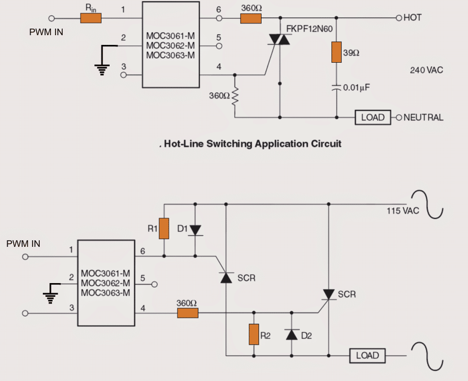
The above image shows how the switch ON soft start PWM control may be implemented on heavy motors for the intended purpose.
In the image above we see how triac driver isolators with zero crossing detector can be employed for driving the motors with the linearly incrementing PWMs for executing a soft start effect.
The above concept effectively takes care of the start ON overcurrent situating on single phase motors.
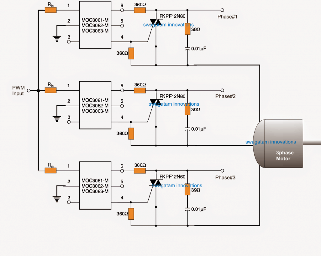
However in case a 3 phase motor is used, the following idea can be used for implementing the proposed 3 phase soft start on motors.


Questions & Answers
sir i saw your article for 1watt led driver Transformerless circuit.
https://www.homemade-circuits.com/2012/03/how-to-make-simplest-1-watt-led-driver.html
i this you used 1uf/400v PPC capacitor for producing 350mA current to drive 1 watt led.
but in your 2nd article for Calculating Capacitor Current in Transformerless Power Supplies.
https://www.homemade-circuits.com/2015/01/calculating-capacitor-current-in.html
you said 1uf/400v PPC capacitor can produce approx 69mA current.
then how it is possible 1uf/400v PPC capacitor can produce 350mA current to glow 1watt led.. if 69mA current is used to glow LED then led glow very dim.
plz explain me. i cant understand
Yes that's right, the proposed circuit will light up the LEDs at 70mA……….to counter this you can use 4 LeDs (1 watt) in series to produce an equivalent light of a 1 watt LED….4 LEDs will mean more money spent on the LEDs, but since it will not demand the need of heatsinks and special aluminum back PCB, so the cost will balance out ultimately
sir previous i glow 3 led of 1watt in series through 12V 500mA local ac adapter. but the cost of this adapter is approx 80rs.. sir can u give me 12V or 18V 500mA ac adapter circuit.? which i can build easly at home at cheap price..
thnkx in advance.
Rahul, Rs.80 is also cheap, making it at home will cost almost this much…the transformer will cost around Rs.40, and the rest Rs.15/- so that's Rs.55 plus a lot of hard work…
anyway, you can try the following circuit:
https://www.homemade-circuits.com/2012/02/how-to-make-current-controlled-12-volt.html
thanku sir..
i saw your another smps led driver circuit.
https://www.homemade-circuits.com/2014/02/simple-1-watt-to-12-watt-smps-led.html
this two diode are not available in market.
1. ST1MDICT
2. STTH1R06A.
Any alternative of this two diode.?
plz tell me..
and if i make this circuit it get work on 220/230VAC mains ???
Hello Rahul, you can use 1N4007 for ST1MDICT, and BA159 for the other one.
yes it's designed to work with any input between 80V and 270V AC/DC
Plz tell me the ckt pf 220v ac to 220v dc with dc voltage regulator
you can try the following circuit:
https://www.homemade-circuits.com/2015/05/smps-mains-voltage-stabilizer-circuit.html
hi Swagatam. i want to know that the circuit mentioned has any affect on electricity consumption? as motor needs more current in starting phase? if yes then can this circuit be used with air conditioners compressor?
Hi Muhammad, yes the current will be initially low and will gradually increase as the PWMs widens so this will enable a slow start or a soft start to the motor.
the time delay can be altered by altering the value of C5 appropriately
thanks for the reply swagatam. so can i use this circuit with my ac? i am also trying to make stablizer for my ac as those available in markets are very expensive. which of ur stabilizer designs will work with that and what rating of auto transformer should be made for said purpose?
yes you can use the above designs with any motor as per the indicated methods.
here's one stabilizer circuit which you can try for your preferred application
https://www.homemade-circuits.com/2011/12/how-to-make-accurate-7-stage-op-amp.html
thanks for the reply Swagatam. so can i use this circuit with my ac? i am also trying to make stabilizer for ac as those available in market are expensive. which of your stabilizer designs should i consider and what should be the auto transformer rating for the said purpose? plz also let me know that can we convert normal ac into inverter ac?
ac for air conditioner
and is it possible to convert normal ac into inverter air conditioner?
it looks like it can used like an inverter AC, but it will need to be thoroughly tested first and experimented so that the results become perfectly verified.
you will need the assistance of an expert engineer for implementing the tests.
I understand the first circuit sir.please give the information about a second circuit sir.I am planning to implement it on my college lab as my mini project. Please reply sir
the second circuit is meant for AC operated motors, the PWM from the first circuit is fed to pin1/2 of the optocoupler in order to implement the soft start over the connected AC motor on the right side with the triac stage
Sir I have some doubt please clarify it. In our college while performing the experiment we use auto transformer as a starter by adjusting there tappings we can start the ac motor smoothly. Disadvantage of auto transformer is its more costier. While seeing this circuit I hope that its cost less while comparing to auto transformer so that I planned to implement it. By pwm technique we need to adjust the pulse given to a motor at the starting and finally width of a pulse becomes maximum so that motor starts smoothly as per your first circuit how can I vary the pulse in a first circuit I need to use a pot for controlling the reference voltage?
2)sir please give detail information about optocoupler I didn't know any think about this please share any other website link about optocoupler.I need a detail information about the optocoupler u mentioned here.please help me sir. I am new to electronics but I have a eagerness to do it
Vijay, you can vary the PWM manually by replacing R9 with a 1K pot, and by eliminating C5.
Opto-couplers are devices which enable isolating two stages in a circuit where the two stages may be at extreme levels and needs to be completely isolated….for example in SMPs the output DC is controlled by the input AC stage through a feedback from the DC stage to the Mains AC stage through an optocoupler.
the MOC series which is shown in the above article is a more advanced opto, since it has a feature called zero crossing detector….you can check the datasheet of this part for a detailed info.
Thank you very much sir for a detailed info.I appreciate your fast reply sir.keep it up sir.we need a person like you for our doubts
you are most welcome!
Hello sir, i'm interested in using this design on an old monarch lathe. It's a large machine running 230v three phase power, would this design work in that application?
Hello Thomas, according to me it should work.
but make sure you confirm the PWM circuit first using a scope and only then integrate it with the last opto circuit
…also make sure the triacs are adequately rated for handling the machine current.
Has it been practically tried with the triac and the opto? Or tried just till the 555 output. .
no, the opto section is not yet tried practically, but according to me it will work without any doubt
Sir, opto coupler with zero cross detection is not working for pwm input with frequency oh 10Khz
Swaroop, use a Darlington transistor for T2, and increase the value of C5 to 1000uF and check again.
Hello Swagatam, first of all BIG THX for your awesome work!
I am going to build a 1-phase-to-3-phase AC motor inverter. It will use a separate opto-isolated IGBT driver on 20 VDC. The diagram above could be used as the initial logic circuit to supply the driver with PWM signal. I am wondering how would your diagrams change if I intend to use 5V logic circuit instead of 12V. Any suggestions?
Thank you Julio, the first circuit can work with any voltage between 5V and 15V, so there's nothing that would need to be changed for a 5V operation, if possible use the CMOS (7)555 ICs instead of the indicated analogue 555 ICs, for getting perfect results.
in fact I am thinking about using a 556 IC. It's two 555 timers in one package, isolated, only sharing Vcc and GND. I have to check if there's a CMOS version of that. Thank you.
OK, thanks!
I'm a noob, but maybe it will help others wondering like me:
I checked on my parts supplier website. They have two kinds of 555 and 556 ICs – 4.5-18V 0.5MHz or 2-18V 2.7MHz. While not specified (on their webpage), those second ones are CMOS. Seemed like an overkill at first for 20KHz, but now it makes perfect sense. Thank you again.
you are welcome julio!
Mr Majumdar can i use the above soft starter circuit to an underwater pump 30hp?the voltage is 400V 50hz 3 phase..is there any problem with the starting current?
Mr.Giannis,the first and the second circuits are confirmed but the last circuit is not yet tested…however I believe it would work as proposed in the article….you can try it out there's no harm in it.
The triacs could be replaced with the following one for max safety and reliability:
https://www.homemade-circuits.com/2012/12/high-current-triac-bta41600b-datasheet.html
Ok ill try it..Thank you very much!
good day sir., i would like to ask if you have a complete calculation of the ckt i want to how did you arrive with those components im an electrical student i only have little knowledge of electronics. thank you sir
the subject can be quite extensive, not possible to explain in few sentences, because there could be strings of explanations one relating to the other and will need to be too elaborate.
ok sir. thank you…sir i did simulate the pwm but i didnt meet the expected output…i did follow the connection.
Jemimah, simulation results are never reliable, please build it practically and check with a scope.
thank you sir i will make as soon as possible and tell you the result…sir i would like to ask what is the process in the triac power driver? what is the use of the triac and optocouplet that it can create a soft start in motor?.. thanks sir
the opto coupler acts like a buffer in between the PWM source and the triac and makes sure that the triac is driven perfectly by considering and adjusting many parameters which relieves the user from designing precision external triac driver stage and related protection circuitry.
good day sir..based on my research, there s already a triac inside the optocoupler, so why use another triac that is connected to pin4? thanks sir.
the internal triac is a low power triac and cannot be used for powering heavy loads.
sir, in the three phase soft start ckt, what is the value of the resistor connected in pin 1?
it can be any value between 1k and 10k
good day sir.we already construct the pwm and the circuit for three phase, we applied it into a lamp instead of a motor..why is it that the circuit did not work on a lamp?
that's not possible, in fact an incandescent lamp would be more responsive to a PWM dimming….however if you are referring to a CFL then may be it could be a valid occurrence.
sir regarding to her question..the output of the pwm is directly 12v output…why is it so?
because the supply is 12V so the output from the IC will also be at 12V
Good day sir. Sir I want to ask about the comparator. Can I ask for its calculation?
Good day Rea,
you can find the details here:
https://www.homemade-circuits.com/2011/12/constant-torque-dc-motor-speed.html
good day sir. why is it that the output voltage that is to be supplied to the motor is only 7volts, the 3 wires connected to the motor are all 7 volts.
good day ecnemay,
are you referring to the third circuit?
did you connect mains 3 phase across the shown points in the third circuit? please elaborate on this?
good day sir, we checked again the voltages of the three wires connected to the motor, it all turned out 210V. the tester we used in which it reads 7V is damaged.sorry 🙂
OK that's fine…thanks for updating the fact.
good day sir.. what are the specifications of the motor used in your design?
good day ecnemay, all DC motors will work with the the first circuit after a transistor driver stage and AC motors with the second and the third circuits.
power of the motor will depend on the rating of the power devices used
sir if you are going to run a motor using this design, what motor will you use? in terms of its power. .
and also sir, if we used 0.5hp induction motor, do we have to change the ratings of the components (e.g. resistors/ capacitors)? or do we have to modify the circuit.
you can run a 100 watt motor with the second and the third circuit
sir, what are the voltage ratings of the three 0.01microfarad in ckt 3. we used 25v capacitor but it burnt out. we replace it with 0.01microfarad 200v capacitor, but there is no output voltage when it is connected to the load. if it has no load, the output voltage is 230v balance. what do you think is the problem in your ckt..? why is it that the voltage is zero when connected to the load. thanks.
ecnamay,
the voltage rating of the capacitor should be obviously high, since you are working with mains voltage. it should be 400V in the input is 230V…
You might have done something seriously wrong or or may your parts are of low quality and that's why not working.
the circuit idea is perfect and will work immediately but only if it's done by proper understanding.
we tried it in a single phase motor, it did work but no changes in its starting current.
did you confirm whether the first circuit was correctly built or not? and whether it was generating the PWMs or not?
Dear i'm having 330ohm instead of 360ohm is it enough? In the third circuit…
yes that will do!
Hi, could you tell me what the value and wattage of R1 + 2 should be in the third circuit? Also the amp rating of D1 + 2. I will be using the circuit to soft start a 1 1/2 HP pool pump, 120 VAC 12.5 FLA.
Hi, all resistors can be 1/4 watt rated, the diodes can be BA159
What about the values of R1 + R2 ?
360ohm 1/4 watt will do for both
Hi mr. Swatagam
Could you pls. give the parts spec. for the 110v " Hot line switching circuit" the one with the SCRs
or if i could use the 220v circuit for 120v line what would be changed for that?
(Benchsaw 110v 12amp)
Your input is very well appreciated.
Roger
Hi Mr.Roger, R1, R2 can be 360 ohms 1/4 watt and the SCRs rated at 15 amps
I believe that the 220V version using triac would also work normally with a 120V input and loads
thanks, much appreciated
Hello, i am using your circuit to soft start a engine starter (car), but it is going from 0 to 12V really quickly, changing R1 and R3 to 1M went from 1ms to 32ms of rising time, but this is too much low for me yet, i need it to be around 2-3s of rising time. Do you know what i could do ?
Really thanks in advance.
Hi, R1 is not related to PWM adjustment, you should try increasing the value of C5 for getting lengthier soft starts…if possible use a Darlington for T2 for a better response
Swagatam, I have been reading your design for a PWM-based soft start for a motor. I really like the 2 x 555 design (which, I guess, could be implemented with a 556 dual timer chip). What puzzles me is the interface between this PWM circuit and the mains electricity. The output of the PWM circuit is asynchronous with the mains, but the 3061 forces synchrony with the mains (50Hz in my case) through the zero-crossing detector. You didn't give the frequency of the oscillator, but I presume it is faster than the mains. I don't doubt that you have tested it, but I can't see how it works. As my motor is a universal motor (in a table saw), and would run quite happily on DC, would it not be a better idea to rectify the mains for the motor, then use the PWM to switch an IGBT on the earth-side of the motor? That way, the mains frequency doesn't really come into the question. I guess it would need a transistor between the timers and the IGBT – even though the gate is insulated.
Thanks Mij,
you are right the design looks quite complex to interpret and set…. the PWM is actually asynchronous with the 3 phase cycles that's the real issue. yes The frequency will need to be around 4 to 5 times faster than the 50Hz or 60Hz.
I have been struggling with a simlar issue in the following article too:
https://www.homemade-circuits.com/2016/07/3-phase-induction-motor-speed.html
and therefore the mosfet bridge driver concept appears to be a much easier option than through triacs, I'll try to update one soon here.
In fact the following concept could be tried for implementing a PWM soft start using mosfet drivers
https://www.homemade-circuits.com/2016/12/diesel-generator-rpm-controller-circuit.html
this shows a single phase control, but the same could be implemented using a 3 phase driver IC.
T1 is for ensuring that the PWM do not get affected with a fluctuating DC supply to the circuit….if your DC is constant you can remove the T1 and the associated parts…
Hallo. I have two questions.
Would be possible use the 3 phase softstart use in Europe? There is 3 phase voltage 3x 400V.
And, I'm not sure, what is PWM input in left side of the circuit. Is possible use a switch?
Regards,
Mike
Hello, yes the design can be used for any 3 phase induction motor in any country, the PWM input is derived from the first circuit..and this must be set correctly for achieving the soft start.
hii
can u please tell how much apprpx. current can be reduced if we use it with single phase induction motor 3 hp runnig amp at full load is 15amp.
the current will start from minimum and then settle to the specified normal value (15 amp) with this soft start circuit, however the above design needs some corrections , I'll try to do it soon.
Hi Swagatam, glad to come across your site. Thanks for posting all good ideas. I have a question on the above PWM Motor SoftStarter circuit.
Can I replace FKPF12N60 with BT139 / BTA16/600B etc. ???
Thanks Chandra, it’s my pleasure!! yes you can try a higher rated triac, because I am sure the MOC is rated to produce at least 30mA output to trigger these triacs satisfactorily.
Thank you very much Swagatam for quick response.
you are welcome Chandra!!
Sir, can i use the above soft starter circuit for 10HP 3 Phase motor instead of using star, and after soft start can i bypass?
Swaroop, you can try it, by suitably adjusting the PWM duty cycle…
use a Darlington for T2 and use 100K for R9
ok thank you sir.
Hello. Very interested in your PWM generating circuit. Your motor driver circuits with the triac and the SCR are for AC motors. Like your correspondent who wants to soft start a car starter motor, I require to soft start the starter on a motorcycle. Both of us need a DC driver circuit providing rather large currents. Can you help please.
Could you please specify the motor specifications, is it a DC motor?? If it is then you can easily drive it by usingg a TIP35 transistor with pin#3 of IC2 in the first diagram, and by attaching motor between the positive battery supply and collector of the transistor…the emitter will connect with the ground of the motorcycle or the battery negative, and the base of the BJT can be connected to pin#3 through a 220 ohm 1 watt resistor
Hi,
Could you please tell me the value of resistor Rin.
Thanks,
Mohan
you can try 4k7 resistors
Hi Sir Swagatam, we have an electric tricycle with a 500W 48v differential motor with 3 speed switch and powered by a 48v 20Ah battery.
Would you please recommend a suitable soft start circuit for this kind of motor ( differential )
if ever, should i power it separately or just tap it to one of the 12v from the 48v battery supply?
Hi Amor, although I do not know much about differential motors, I believe the second circuit from the above article will be able to implement the required slow start to your motor perfectly, you can give it a try…
Thank you Sir Swagatam, is there any replacement for the mosfet IRF540? what about F9540N?
about the watt ratings of the resistors, are they all 1/4 watt?
Hi, F9540N is same as IRF9540N which is the P version of the IRF540, it won’t work since the soft start action would be simply reversed…it may work if a NPN BJT is used as the buffer in the middle
Good day Sir Swagatam,
how could i integrate the above 2nd circuit in a electric rickshaw unit that has a 3 speed and a reverse functionality? does the soft start also affect the reverse mode?
it is okay to charge the battery (48v ) from ac outlet while the soft start circuit permanently connected?