The IRF540N is an advanced HEXFET N-channel power mosfet, from International Rectifier. The device is extremely versatile with its current, voltage switching capabilities, and thus becomes ideal for numerous electronic applications.
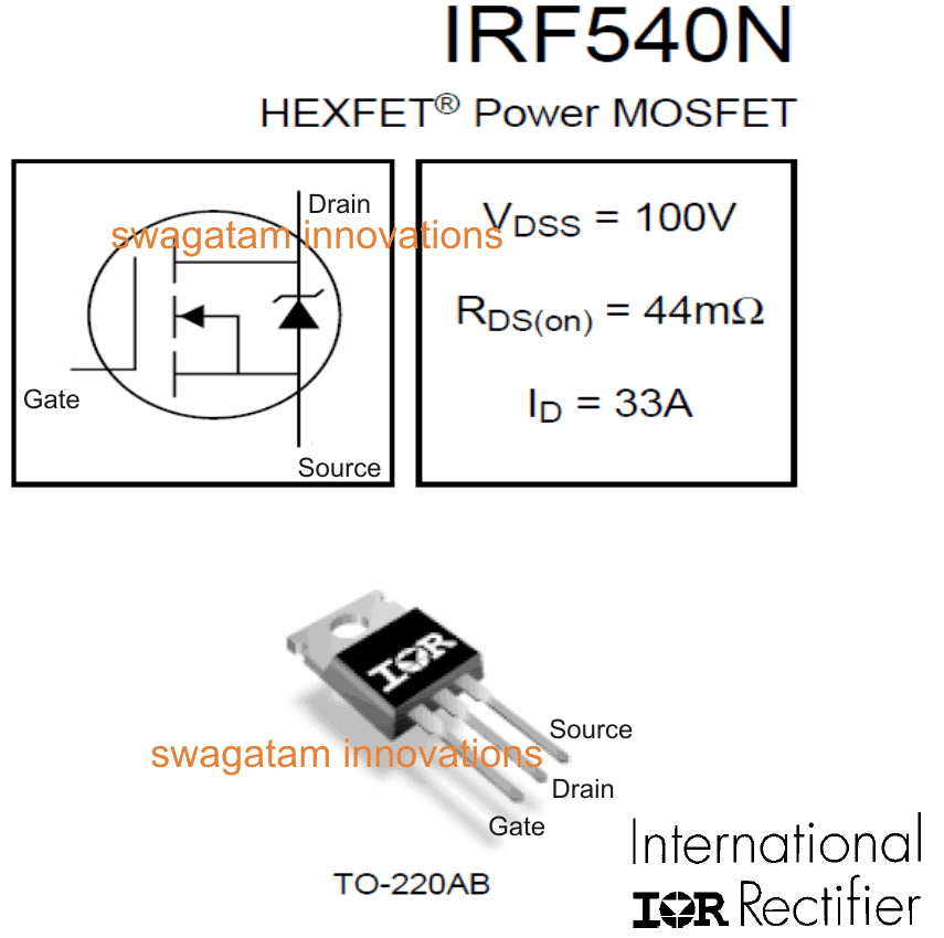
The datasheet and pinout details of the device has been explained in the following article.
Main Features:
- Sophisticated, cutting-edge processing technology used.
- Extremely low resistance across load path. Flexible dv/dt plot.
- Operating temperature tolerance capacity as high as 175 degrees Celsius.
- Very fast switching capability.
- Fully resistant against avalanche or peak surge currents.
Pinout Image
Maximum tolerable limits of IRF540N are stated as under:
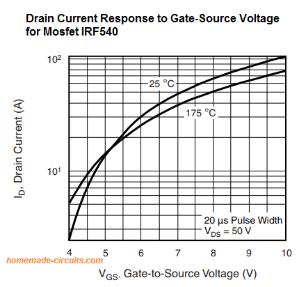
ID = 33 Amps Max at 10V (VGS), It’s the maximum current handling capacity of the device across the drain to the source, via the load, with gate voltage at 10V, at normal temperatures (25 to 35 degrees Cel.)
IDM = 110 Amps Max, It’s the maximum current handling capacity of the device across the drain to the source, via the load, in a pulsed mode (NOT continuous).
PD = 130 Watts Max, The maximum power the FET can dissipate with and infinite (cool) heat sink
VGS = 10 Volts typical +/-20%. It’s the maximum trigger voltage that may be applied across the gate and the source for optimal performance.
V(BR)DSS= 100 volts, It’s the maximum voltage that may be applied across drain to source of the device.
Applications Areas
This device is best suited for high power DC switching applications, such as in high current SMPS power supplies, compact ferrite inverter circuits, iron core inverter circuits, buck and boost converters, power amplifiers, motor sped controllers, robotics etc.
How to Connect IRF540N MOSFET
It’s quite simple, and must be done as explained in the following points:
The source should be preferably connected to the ground or the negative line of the supply.
The drain should be connected to the positive terminal of the supply via the load which needs to be operated by the device.
Finally, the gate which is the trigger lead of the device should be connected to the trigger point of the circuit, this trigger input should be preferably a +5V supply from a CMOS logic source.
If the trigger input is not a logic source make sure the gate is permanently connected to ground via a high value resistor.
When the device is being used for switching inductive loads like a transformer or a motor, a flyback diode should be normally connected across the load, with the cathode of the diode connected to the positive side of the load.
However, the IRF540N has a built in avalanche protective diode, therefore typically an external diode may not be required; it may be incorporated in case you wish to provide extra safety to the device.
Application Circuits
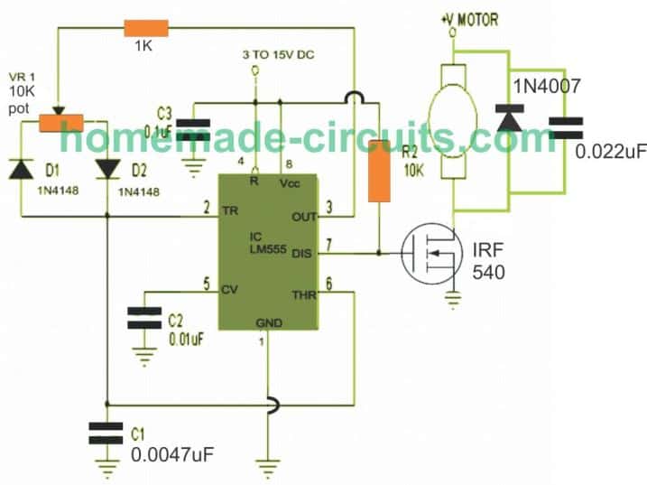
Motor Control: All motor control applications require the power device to be rugged, high current, and high voltage rated, and also with a high speed switching. The IRF540 satisfies all these criteria and becomes perfectly suitable for all DC motor control designs, as depicted below:

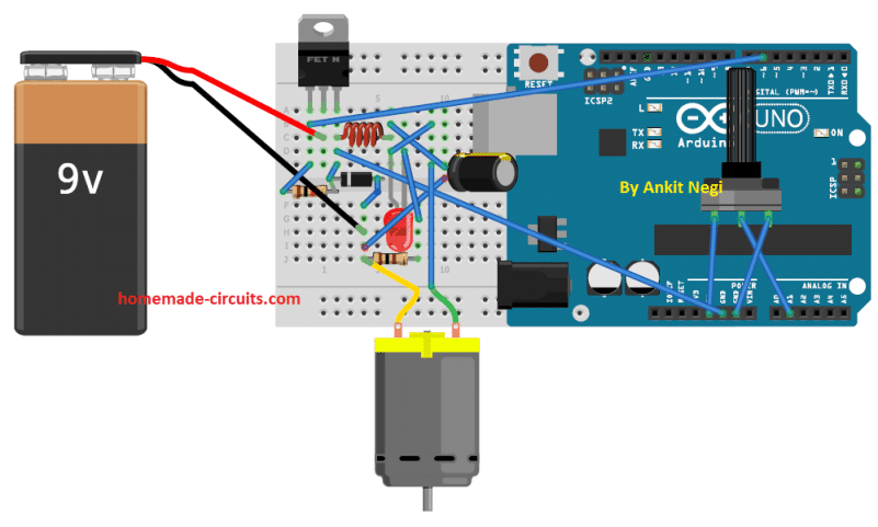
Buck Converter: Buck converter cannot work with devices rated with ordinary voltage, current and switching levels. The IRF540 as we have discussed in the above datasheet and features is equipped adequately to work under moderately high voltage, high current and outstanding switching speeds, which makes it a perfect candidate for all buck boost switching applications.
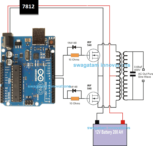
Power Inverter: IRF540 are rated with massive power which allows it to be ideally used for making power inverters as shown below. The complete code can e found in this artcile.
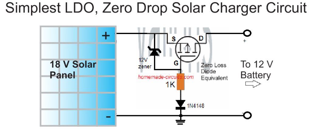
Zero Drop Solar Switch: Solar panels today are rated massively, and this calls for controller with substantial power handling capacity. The IRF540 become highly suitable for all high power solar controller applications simply due to its impressive power switching capabilities.
Corrections to the above explanations is welcome.


Questions & Answers
sorry, i did not understand your question….
Sir is there anything wrong with connecting two or three irf3205 fet in parallel in an inverter that is supposed to work on 12v 36amp battery? If yes suggest the mosfet and the number to connect in parallel as i only want 300watt at the output and (2) how can i know a 350va transformer by just physically looking at it.
victory, single IRF3205 mosfets would be enough for achieving the required 300 watts…more in parallel won't be required, just put these on good heatsinks.
you can expect a 350vA trafo to be minimum 8 to 12kg heavy
sorry, I can't figure it out, looks difficult
Sir,
Pls give me circuit dia of irf540 inorder to control speed of a dc fan (12 v )
Dhanlal, you can try the following design
https://www.homemade-circuits.com/2012/05/make-this-pwm-based-dc-motor-speed.html
Dear Sir
We need a MOSFET with following specifications to be used in High voltage inverter circuit
a) Vds:500v
b) ID: 50Amps continuous
c) Fast Switching
d) upto 175 degree Celsius
Hi Mohinder,
you can try the following mosfet
STY60NM50
But a suitable heatsink will be mandatory, just as for any other mosfet
says 33amp at a maximum of 10 volts. not 100
Thanks sir, please how many watt 33amp is equal to, am guessing 330w right? What am trying to understand is how many Watt’s is irf540?
Andrew, multiply the Vds and Id ratings of the mosfet, that will give you the maximum wattage handling capacity of the mosfet, provided its temperate is not allowed to 60 degrees Celsius through proper heatsink.
I applied 12v 62A battery as load to IRF540N attached to heatsink yet my IRF540N was extremely hot, the circuit is about high voltage cut of in battery charger. The input voltage is 15V
use more cooling through fan or water…or use more number of MOSFeTs in parallel….
I really appreciates your effort, to having dedicated your life to be a blessing to we, the your generations. Sir can you please enlighten me on how to build a cycloconverter for carrying (lowering) AC frequency
Thank you for your appreciation, If possible I’ll to post a related article on this topic.
Good evening Mr.swagatam.
1.Can I use irfz44n inplace of Irf540 in 12v dc motor speed controller. 2.can I use irfz44n inplace of irfz24n in 12v dc motor speed controller
Good evening BLV, yes you can use the mentioned MOSFET.
Thank you very much for the prompt reply. By your reply I understand that irfz44n can replace both irfz24n and irf540.Iam correct?
Yes, you are absolutely right, assuming your load operating voltage is less than 40V
I once again thank you for the prompt response. I really appreciate your good work in helping people
You are most welcome!
Good day Mr. Swagatam. Pls wat will be the drain current if I used a 5v gate voltage on irf540 MOSFET……
I couldn’t find the formula to calculate it myself
Hello Vichye, The drain current will depend on the drain load and the RDSon resistance of the MOSFET. However at 5 V the MOSFET can heat up….you must use a minimum 9V or 12V.
???????? I used irf540 MOSFET
I’m trying to control (select a tab) on a resistor ladder by using a UNO to read a 1-5VDC output from a tank sensor, then based on the mapped output select a tab on a 30 to 240 resistor ladder. I am trying to present a resistance to a resistance to a gauge to indicate the level in the tank. I am experminting with relays, but would like to move to an all solid state circuit and am trying to figure out how to use something like an IRF540N. Am i way off base or do you have any eamples that you can point me to to help me better understand how I might accomplish this? Many thanks, enjoy you website.
Sorry, I am having difficulty understanding your circuit setup. If you can show the setup through a schematic diagram, then perhaps I might be able to figure out an appropriate solution using MOSFETs
sir Swagatam….
I just wanna know the difference between this mosfet
IRf540n and A2099 in inverter
Hi Klinton, I cannot find the datasheet of the MOSFET A2099 so i can’t identify its specifications.
Sir can I use irf540n for series voltage regulators
Hi G Suresh, yes you can use it but with a MOSFET the output source voltage might be around 3 to 5V lower than the input voltage.