Zener diodes that are normally available are mostly 1/4 watt or 1/2 watt types. And it is quite valid since the basic function of zener is to create stabilized reference voltage. Zener diodes are not designed for current regulation directly.
However, for some applications where shunting excess voltage and current is necessary a high current or high watt zener diode becomes useful.
The 1N53 series provides a complete range of high watt zener diodes specially created for high current and voltage regulation.
The maximum power is 5 watt and voltage is upto 200V. Dividing the wattage with the voltage rating of the diode gives its effective current handling capacity.
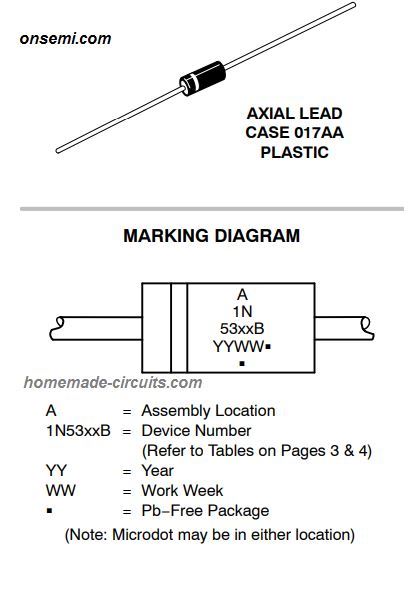
The pinout and marking diagram are shown below:
Main Features can be studied as given below:
Voltage Range − 3.3 V to 200 V
ESD Rating of Class 3 (>16 kV) per Human Body Model
Surge Handling Capacity of up to 180 W for 8.3 ms
Maximum Steady State Power Dissipation @ TL = 25°C, Lead Length = 3/8 in Derate above 25°C is 5 watts
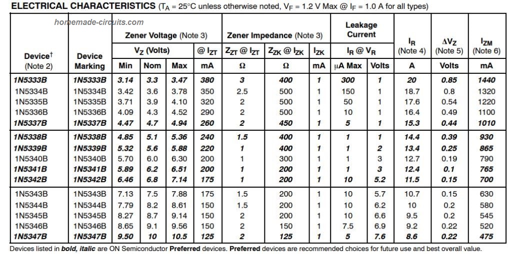
ELECTRICAL CHARACTERISTICS
The following list gives the various symbols used for indicating the electrical parameters and tolerance levels of the device. (TA = 25°C unless otherwise noted, VF = 1.2 V Max @ IF = 1.0 A for all types).
- VZ = Reverse Zener Voltage @ IZT
- IZT = Reverse Current
- ZZT = Maximum Zener Impedance @ IZT
- IZK = Reverse Current
- ZZK = Maximum Zener Impedance @ IZK
- IR = Reverse Leakage Current @ VR
- VR = Breakdown Voltage
- IF = Forward Current
- VF = Forward Voltage @ IF
- IR = Maximum Surge Current @ TA = 25°C
- VZ = Reverse Zener Voltage Change
- IZM = Maximum DC Zener Current
By referring to the above symbols we can easily check the voltage and current specifications of the high power zeners diodes from the following table. This table can be used for selecting the preferred zener diode as per our requirements:
TOLERANCE AND TYPE NUMBER DESIGNATION: The JEDEC type numbers shown above symbolize a tolerance of ±5%.
ZENER VOLTAGE (VZ) and IMPEDANCE (IZT and IZK): The zener voltage test condition and its impedance can be learned from this data:
Current IZ is applied 40ms ±10% before the measurements.
Mounting terminals are positioned 3/8″ to 1/2″ above the inner margin of mounting clips to the diode case (TA = 25°C +8°C, −2°C).
SURGE CURRENT (IR): Surge current is defined as the maximum peak, non−recurrent square−wave current having a pulse width, of 8.3 ms that can be tolerated by the device.
The information available in the following image can be referred to identify the maximum surge current for a square wave of any pulse width between 1 ms and 1000 ms.
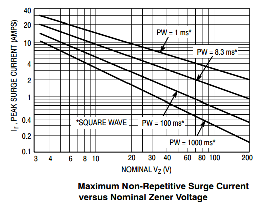
This may be implemented by plotting the relevant points on logarithmic paper. The above figure shows an example result for a 3.3 V and 200 V zener.
VOLTAGE REGULATION (DVZ): The voltage regulation specifications for this series can be studied as given below:
VZ measurements are established at 10% and subsequently at 50% of the IZ max value as per the info provided in the electrical characteristics table. The time duration for the test current for each VZ reading was recorded as 40 ms ±10%.
How to Identify Maximum Current Handling Capacity
MAXIMUM REGULATOR CURRENT (IZM): This can be calculated by referring to the maximum voltage of a 5% type unit. Meaning this is applicable only to the B−suffix device.
The effective current handling capacity IZM for any of these high current zener diodes cannot be exceeded the over 5 watts divided by the actual VZ of the device. With a condition where TL = 25°C at 3/8″ for the device body.
Meaning, suppose you are using a 3.3V zener, then the maximum tolerable current for this device can be calculated by dividing 5 with 3.3. That's equal to around 1.5 amp.
† The “G’’ suffix tells us about Pb−Free package or Pb−Free packages that are presently available.
High Current Zener Diode Application
As stated earlier a high current diode can be used in applications where power dissipation may be OK and not a factor to be considered.
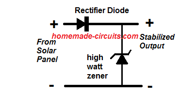
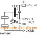
Solar Panel Output Control
For example it can be used for controlling a solar panel output effectively without involving complex and expensive controllers. The following image shows the bare minimum setup required for implementing a panel output control using a high power zener diode.
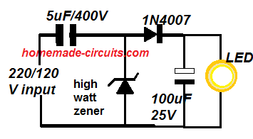
Simple LED Driver
A high current diode can be also effectively used for manufacturing cheap yet highly reliable LED drivers, as shown below:
Over to You
OK so this was a short description regarding the specifications of high watt zener diode IN53. The tutorial explained us regarding the electrical features, tolerance, and how to use this type of zener diodes in practical application designs. I hope you liked. If you have any further doubts or suggestions, you may express them through comments below.


Questions & Answers
Hi Swagatam,
I have a challenge for you.
I have a boost converter that I want to charge a 9V NiMH battery from.
(forget about what is driving the booster, it’s not relevant)
A 9v NiMH needs 12.8 volts to charge it, but the battery can have residual voltage. So for example, let’s say the battery has 8 volts.
Lets say the storage capacitor on the output side of the booster has 22 v.
Wouldn’t the Vz have to be 12.8 plus the residual voltage to charge properly?. In this case Vz = 20.8V ? What would the circuit look like if you wanted to be really thrifty and not limit the voltage on the storage capacitor or lose its charge to ground during regulation?
I would send you a diagram of what I was thinking but I don’t know how to attach anything to a comment.
Hi Cris, that makes sense, to limit the voltage to 12.8V the zener voltage must be also 12.8V. However if the circuit has some additional configurations such as a voltage divider network, or if the zener is connected through a feedback etc, then the zener voltage might need to be higher.
Unfortunately an image upload feature is not available in this comment section.
Hi. I wonder if you can help me.
I have an input voltage which ranges from 0v to 20v
I need a device that will give me 0v from 0-18v and then 18-20v above 18v
Current is low in the region of 250mA
I thought I could do this using Zener diodes but I’m getting confused.
Thanks for your help
Paul
Hi, how is it possible with zeners? Can you please explain. I don’t think zeners can help? You will need an LM338 regulator and an opamp circuit for toggling the current.