• Skip to main content
  • Skip to primary sidebar

Homemade Circuit Projects

Get free circuit help 24/7

New Projects | Privacy Policy | About Us | Contact | Disclaimer | Copyright | Videos 

Op Amp Basics | 555 Circuits | Hobby Circuits | LED Driver | For Beginners | Basic Circuits | Transistor Circuits | Voltage Regulators 

You are here: Home / 741 IC Circuits / Op amp IC 741 Datasheet, Pinout, Applications

Op amp IC 741 Datasheet, Pinout, Applications

Last Updated on September 4, 2023 by Swagatam 1 Comment

The 741 is a popular general-purpose operational amplifier (op-amp) IC that was introduced by Fairchild Semiconductor in 1968. It has since become one of the most widely used op-amp ICs in the world, due to its versatility and low cost. Below is a typical datasheet for the IC 741:

Table of Contents
  • General Specifications:
  • Pinout Configuration:
    • Features:
    • Applications:
  • Offset Nulling
    • How to Eliminate 741 Offset Voltage Problem
  • IC 741 Voltage Regulator (Application Circuit)

General Specifications:

  • Supply voltage: +/- 10 to +/- 18V
  • Input voltage range: +/- 15V
  • Output voltage range: +/- 14V
  • Input current: 500 nA
  • Output current: 25 mA
  • Unity gain frequency: 1 MHz
  • Slew rate: 0.5 V/us
  • Input resistance: 2 MOhm
  • Output resistance: 75 Ohm
  • Voltage gain: 200,000

Pinout Configuration:

The pinout details for the IC 741 are as given below:
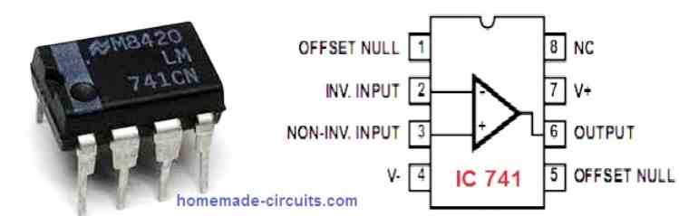
caution electricity can be dangerous
  1. Offset null
  2. Inverting input (-)
  3. Non-inverting input (+)
  4. V- (negative power supply)
  5. Offset null
  6. Output
  7. V+ (positive power supply)
  8. NC (no connection)

Features:

  • High gain (typically 200,000)
  • Wide input voltage range
  • Low input bias and offset currents
  • High output current
  • Compatible with industry-standard TTL and MOS logic
  • Short-circuit protection

Applications:

  • Amplification of analog signals
  • Filtering and signal conditioning
  • Oscillators and waveform generators
  • Voltage regulators
  • Comparator circuits
  • Audio and video signal processing

For more IC 741 application circuits you can refer to the following article:

Simple 741 Circuits
IC 741 Multimeter Circuits
IC 741 Power Supply Circuits

Note: This datasheet is for general reference only, as specific features and specifications may vary depending on the manufacturer and version of the IC. It is important to consult the datasheet for the specific IC being used in any given application.
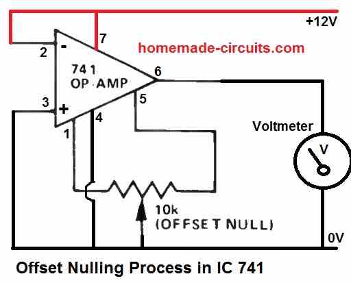
Offset Nulling

The operational amplifier (op-amp) of IC 741 uses a method called offset nulling to reduce or eliminate the input offset voltage.

When the input voltages are the same (that is, when there is no differential input voltage), a very tiny voltage may exist between the op-amp's inverting and non-inverting inputs.

In situations where great precision and accuracy are required, this offset voltage might lead to errors in the op-amp's output.

In other words, the offset voltage can cause the output voltage of the 741 to be somewhere between 0.5 V or 2 V when it is actually supposed to be zero. Meaning, in situations where the op amp output is supposed to show 0 V at the output pin#6, it might instead show a voltage higher than 0.5 V, which can be very undesirable.

How to Eliminate 741 Offset Voltage Problem

The 741 op-amp has two pins with the label "OFFSET NUL" to reduce or remove this offset voltage.

You simply have to connect the two outer pins of a 10 K preset across the OFFSET NUL pinouts of the 741, which are pin#1 and pin#5, and connect the center pin of the preset to the ground line of the op amp.

Next, connect a voltmeter across the pin#6 and ground of the op amp and slowly adjust the 10 K preset until you get a perfect zero volts at the output of the 741 IC.

Remember the above procedures will need to be done while the IC is powered ON with DC. Without supply voltages the above process will not work.

The complete circuit diagram for implementing the offset nulling in IC 741 is shown in the following circuit diagram:

IC 741 Voltage Regulator (Application Circuit)

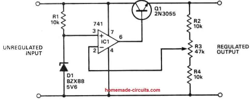
This is a voltage regulator circuit using IC 741 and 2N3055 transistor. Non-inverting pin of 741 is clamped to a 5V zener at the unregulated DC side of the power supply.

The inverting input pin is configured as the feedback and is connected to the slider arm of a pot, the outer pins of the pins are connected to the output regulated DC supply rails.

The output of the op amp 741 is connected to the base of a 2N3055 transistor.

The collector of the transistor is connected to the unregulated + DC input supply, while the emitter forms the output which supplies the regulated DC output.

The output regulated DC voltage can be changed by adjusting the pot value.

You'll also like:

  • 1.  IC 741 Low Battery Indicator Circuit
  • 2.  55V 110A N-Channel Mosfet IRF3205 Datasheet
  • 3.  50 Amp Transistor MJ11032, MJ11033 Datasheet, Pinout
  • 4.  Opamp Hysteresis – Calculations and Design Considerations
  • 5.  IC 4018 Datasheet, Pinout Function Explained
  • 6.  Make a Workbench Multimeter With the IC 741

About Swagatam

Swagatam is an electronic engineer, hobbyist, inventor, schematic/PCB designer, manufacturer. He is also the founder and the author of the website: https://www.homemade-circuits.com/, where he loves sharing his innovative circuit ideas and tutorials.
If you have any circuit related queries, you may interact through comments, and get guaranteed replies from the author.

Have Questions? Please Comment below to Solve your Queries! Comments must be Related to the above Topic!!

Subscribe
Notify of
1 Comment
Newest
Oldest
Inline Feedbacks
View all comments


Primary Sidebar

Categories

  • 3-Phase Power (15)
  • 324 IC Circuits (19)
  • 4017 IC Circuits (52)
  • 4060 IC Circuits (27)
  • 555 IC Circuits (99)
  • 741 IC Circuits (20)
  • Arduino Engineering Projects (83)
  • Audio and Amplifier Projects (126)
  • Battery Chargers (83)
  • Car and Motorcycle (96)
  • Datasheets (78)
  • Decorative Lighting (Diwali, Christmas) (33)
  • Electronic Components (101)
  • Electronic Devices and Circuit Theory (36)
  • Electronics Tutorial (121)
  • Fish Aquarium (5)
  • Free Energy (34)
  • Fun Projects (14)
  • GSM Projects (9)
  • Health Related (22)
  • Heater Controllers (31)
  • Home Electrical Circuits (107)
  • How to Articles (20)
  • Incubator Related (6)
  • Industrial Electronics (28)
  • Infrared (IR) (40)
  • Inverter Circuits (98)
  • Laser Projects (13)
  • LED and Light Effect (98)
  • LM317/LM338 (22)
  • LM3915 IC (25)
  • Meters and Testers (69)
  • Mini Projects (150)
  • Motor Controller (69)
  • MPPT (7)
  • Oscillator Circuits (25)
  • PIR (Passive Infrared) (8)
  • Power Electronics (35)
  • Power Supply Circuits (86)
  • Radio Circuits (10)
  • Remote Control (50)
  • Security and Alarm (66)
  • Sensors and Detectors (131)
  • SG3525 IC (5)
  • Simple Circuits (75)
  • SMPS (29)
  • Solar Controllers (63)
  • Timer and Delay Relay (55)
  • TL494 IC (5)
  • Transformerless Power Supply (9)
  • Transmitter Circuits (42)
  • Ultrasonic Projects (17)
  • Water Level Controller (45)

Calculators

  • AWG to Millimeter Converter
  • Battery Back up Time Calculator
  • Capacitance Reactance Calculator
  • IC 555 Astable Calculator
  • IC 555 Monostable Calculator
  • Inductance Calculator
  • LC Resonance Calculator
  • LM317, LM338, LM396 Calculator
  • Ohm’s Law Calculator
  • Phase Angle Phase Shift Calculator
  • Power Factor (PF) Calculator
  • Reactance Calculator
  • Small Signal Transistor(BJT) and Diode Quick Datasheet
  • Transistor Astable Calculator
  • Transistor base Resistor Calculator
  • Voltage Divider Calculator
  • Wire Current Calculator
  • Zener Diode Calculator

© 2023 · Swagatam Innovations

wpDiscuz