In this project we are going to step down 12 V DC to any DC value between 2 and 11 V. The circuit which steps down the DC voltage is known as buck converter. The output voltage or step down voltage needed is controlled using a potentiometer connected to Arduino.
By Ankit Negi
INTRODUCTION TO CONVERTERS:
There are basically two types of converters:
1. Buck converter
2. Boost converter
Both converters change the input voltage according to the requirement. They are similar to a transformer with one main difference.
Whereas transformer steps up/ down an A.C voltage, D.C converters step up/ down D.C voltage. Main components of both the converters are:
- A. MOSFET
- B. INDUCTOR
- C. CAPACITOR
BUCK CONVERTER: as the name itself suggest, buck means to lower down the input voltage. Buck converter gives us the voltage less than the input D.C voltage with high current capacity. It is a direct conversion.
BOOST CONVERTER: as the name itself suggest, boost means to increase the input voltage.
Boost converter gives us the D.C voltage more than the D.C voltage at input. It is also a direct conversion.
** in this project we are going to make a buck converter circuit to step down 12 v D.C using arduino as a PWM source.
CHANGING PWM FREQUENCY ON ARDUINO PINS:
PWM pins of arduino UNO are 3, 5, 6, 9, 10 and 11.
To perform PWM, command used is:
analogWrite( PWM PIN NO,PWM VALUE);
and the PWM frequency for these pins are:
For Arduino Pins 9, 10, 11, and 3---- 500Hz
For Arduino Pins 5 and 6---- 1kHz
These frequencies are fine for general purpose use like fading a led. But for circuit like buck or boost converter, one need high frequency PWM source (in the range of tens of KHZ) because MOSFET need high frequency for perfect switching and also high frequency input decreases the value or size of circuit components like inductor and capacitor. Thus for this project we need high frequency PWM source.
Good thing is that we can change the PWM frequency of PWM pins of arduino by using simple code:
FOR ARDUINO UNO:
Available PWM frequency for D3 & D11:
//TCCR2B = TCCR2B & B11111000 | B00000001; // for PWM frequency of 31372.55 Hz
//TCCR2B = TCCR2B & B11111000 | B00000010; // for PWM frequency of 3921.16 Hz
//TCCR2B = TCCR2B & B11111000 | B00000011; // for PWM frequency of 980.39 Hz
TCCR2B = TCCR2B & B11111000 | B00000100; // for PWM frequency of 490.20 Hz (The DEFAULT)
//TCCR2B = TCCR2B & B11111000 | B00000101; // for PWM frequency of 245.10 Hz
//TCCR2B = TCCR2B & B11111000 | B00000110; // for PWM frequency of 122.55 Hz
//TCCR2B = TCCR2B & B11111000 | B00000111; // for PWM frequency of 30.64 Hz
Available PWM frequency for D5 & D6:
//TCCR0B = TCCR0B & B11111000 | B00000001; // for PWM frequency of 62500.00 Hz
//TCCR0B = TCCR0B & B11111000 | B00000010; // for PWM frequency of 7812.50 Hz
TCCR0B = TCCR0B & B11111000 | B00000011; // for PWM frequency of 976.56 Hz (The DEFAULT)
//TCCR0B = TCCR0B & B11111000 | B00000100; // for PWM frequency of 244.14 Hz
//TCCR0B = TCCR0B & B11111000 | B00000101; // for PWM frequency of 61.04 Hz
Available PWM frequency for D9 & D10:
//TCCR1B = TCCR1B & B11111000 | B00000001; // set timer 1 divisor to 1 for PWM frequency of 31372.55 Hz
//TCCR1B = TCCR1B & B11111000 | B00000010; // for PWM frequency of 3921.16 Hz
TCCR1B = TCCR1B & B11111000 | B00000011; // for PWM frequency of 490.20 Hz (The DEFAULT)
//TCCR1B = TCCR1B & B11111000 | B00000100; // for PWM frequency of 122.55 Hz
//TCCR1B = TCCR1B & B11111000 | B00000101; // for PWM frequency of 30.64 Hz
** we are going to use pin no. 6 for PWM hence the code:
//TCCR0B = TCCR0B & B11111000 | B00000001; // for PWM frequency of 62.5 KHz
COMPONENT LIST:
1. ARDUINO UNO
2. INDUCTOR(100Uh)
3. SCHOTTKY DIODE
4. CAPACITOR (100uf)
5. IRF540N
6. POTENTIOMETER
7. 10k, 100ohm RESISTOR
8. LOAD( motor in this case)
9. 12 V BATTERY
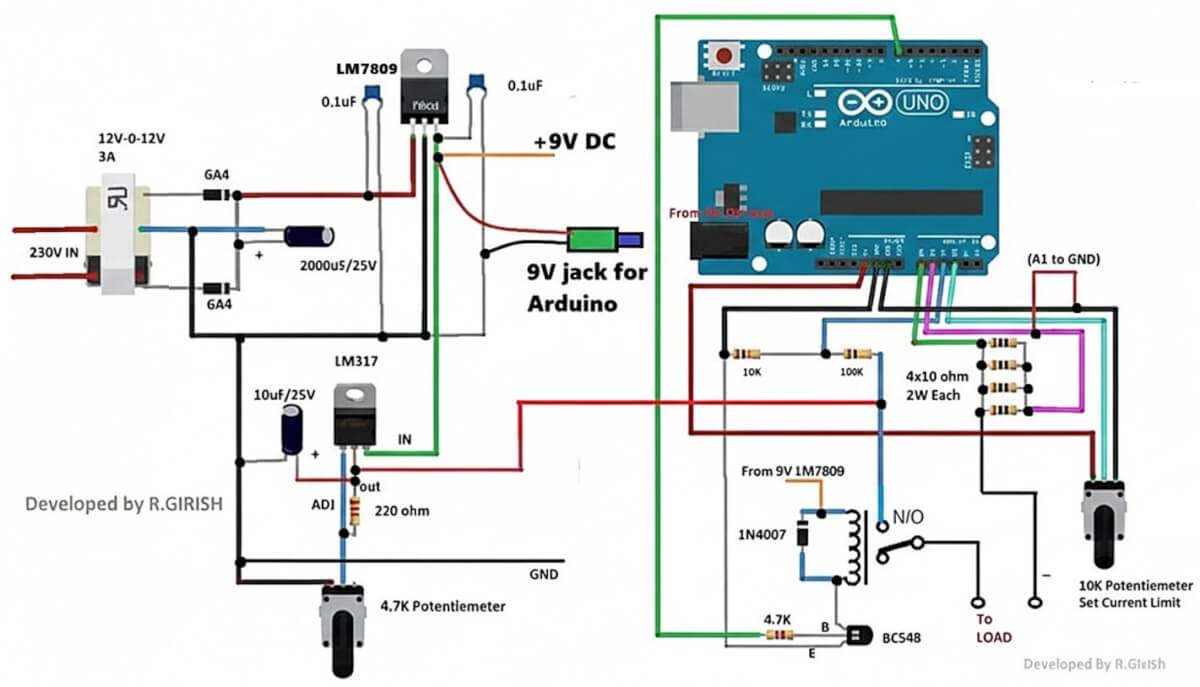
CIRCUIT DIAGRAM
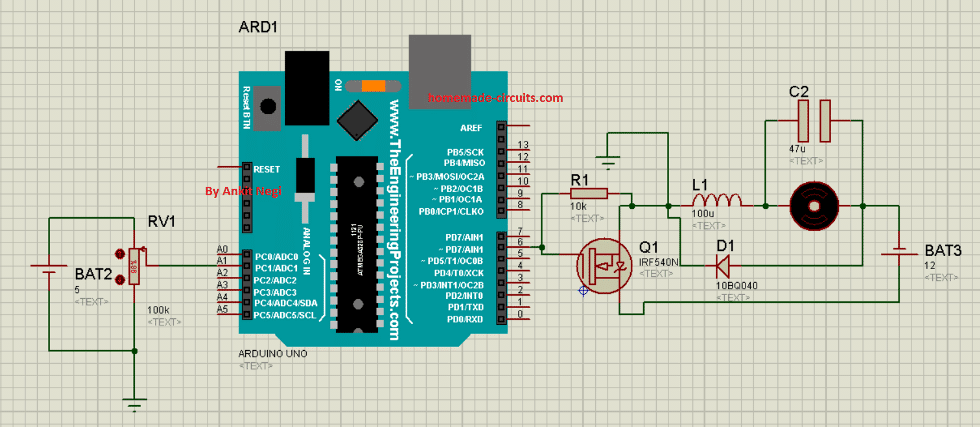
Make connections as shown in circuit diagram.
1. Connect end terminals of potentiometer to 5v pin and ground pin of arduino UNO respectively whereas its wiper terminal to pin analog pin A1.
2. Connect PWM pin 6 of arduino to the base of mosfet.
3. Positive terminal of battery to drain of mosfet and negative to p-terminal of schottky diode.
4. From p-terminal of schottky diode, connect load (motor) in series with inductor to source terminal of mosfet.
5. Now connect n-terminal of schottky diode to source terminal of mosfet.
6. Connect 47uf capacitor across motor.
7. At last connect ground pin of arduino to the source terminal of mosfet.
Purpose of MOSFET:
Mosfet is used to switch the input voltage at high frequency and to provide high current with less dissipation of heat.
Purpose of arduino:
For high switching speed of mosfet (at frequency 65 KHz approx.)
Purpose of inductor:
If this circuit is run without connecting an inductor, then there are high chances of damaging the mosfet due to high voltage spikes on terminal of mosfet.
To prevent mosfet from these high voltage spikes it is connected as shown in figure since when mosfet is on it stores energy and when mosfet is off it give away this stored energy to the motor.
Purpose of Schottky diode:
Assume schottky diode is not connected in circuit. In this case when mosfet is switched off inductor releases its energy to load or motor which have very slight effect on load because there is incomplete loop for current to flow.
Thus schottky diode completes the loop for current to flow. Now a normal diode is not connected here because schottky diode have low forward voltage drop.
Purpose of led: to indicate step down voltage across load.
Purpose of Potentiometer:
Potentiometer gives analog value to arduino (based on the position of wiper terminal) according to which pwm voltage is received by gate terminal of mosfet from PWM pin 6 of Arduino. This value ultimately controls the output voltage across load.
Why resistor is connected between gate and source?
Even small amount of noise can turn on the mosfet. Hence a pull down resistor is connected between gate and ground i.e. source.
Program Code
Burn this code to arduino:
int m ; // initialize variable m
int n ; // initialize variable n
void setup()
{
pinMode(6,OUTPUT) ; // set pwm pin 6 as output pin
pinMode(A1,INPUT) ; // set analog pin as input pin
TCCR0B = TCCR0B & B11111000 | B00000001 ; // for PWM frequency of 62.5 KHz on pin 6( explained under code section)
Serial.begin(9600) ; // begin serial communication
}
void loop()
{
m= analogRead(A1) ;// read voltage value from pin A1 at which pot. wiper terminal is connected
n= map(m,0,1023,0,255) ; // map this ip value between 0 and 255
analogWrite(6,n) ; // write mapped value on pin 6
Serial.print(" PWM Value ") ;
Serial.println(n) ;
}
CODE EXPLANATION
1. Variable x is voltage value received from pin A1 at which pot’s wiper terminal is connected.
2. Variable y is assigned the mapped value which is between 0 and 255.
3. **as already explained in above section for circuit like buck or boost converter, one need high frequency PWM source (in the range of tens of KHZ) because MOSFET need high frequency for perfect switching and high frequency input decreases the value or size of circuit components like inductor and capacitor.
Thus we are going to use this simple code to generate pwm voltage of approx. 65 kHz frequency:TCCR0B = TCCR0B & B11111000 | B00000001 ; // for PWM frequency of 62.5 KHz on pin 6
How it Works:
Since Potentiometer gives analog value to arduino (based on the position of wiper terminal), this determines pwm voltage value received by gate terminal of mosfet from PWM pin 6 of Arduino.
And this value ultimately controls the output voltage across load.
When mosfet is on inductor stores energy and when it switches off this stored energy is released to the load i.e. motor in this case.
And because this process takes place at very high frequency we get a step down D.C voltage across motor which depends on the wiper terminal’s position as mosfet is a voltage dependent device.
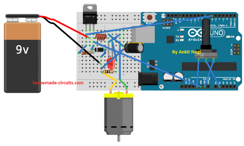
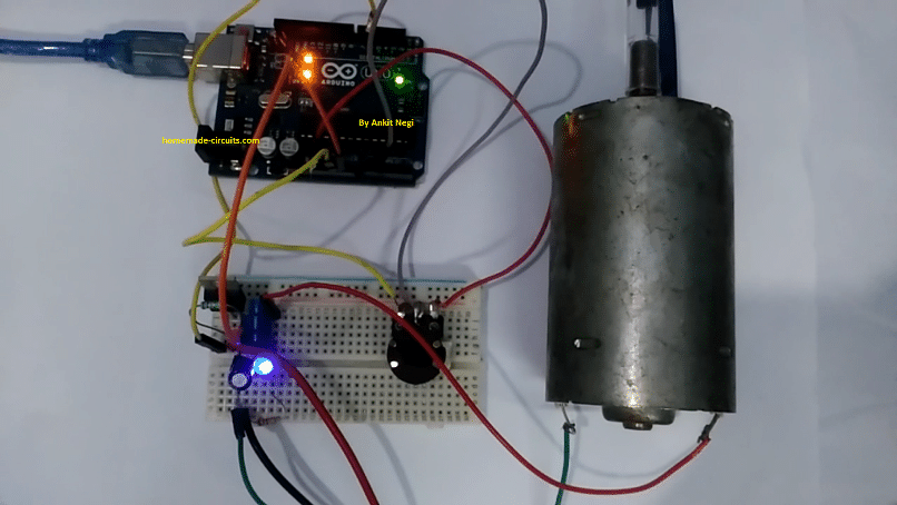
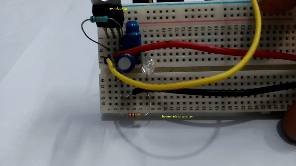
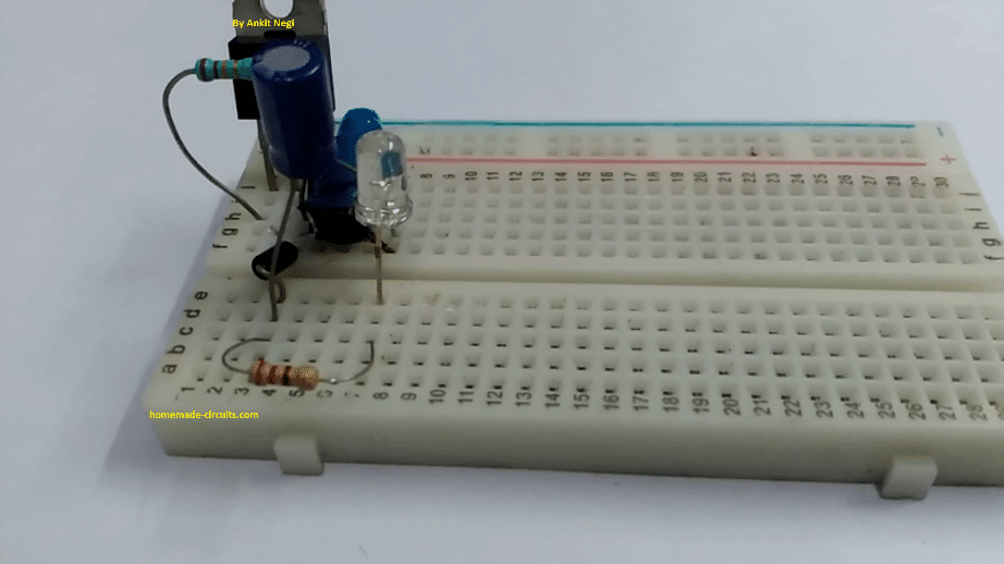
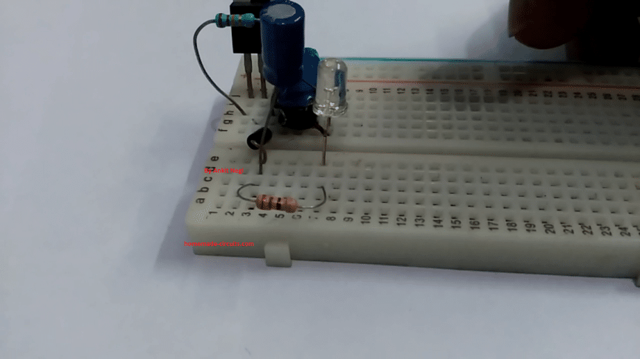
Prototype Images:

Questions & Answers
I have assembled the Proteus diagram, following the list of components you provided previously, but the motor turns very slowly or does not turn at all. I also tried to follow your more pictorial design in Tinkercad, but that didn’t work either. Could you please send me a more updated diagram or tell me exactly which components you used?
Hi, I think you should build and test the circuit practically, because as you can see the design has been tested practically and successfully by the author of the article…so it has to work…
This project is interesting and simple, but you should alert that Arduino ground level is floating, so preventing Arduino from being powered using a DC-DC converter that share the same ground of the main 9 or 12 volt source.
Thank you for your feedback, that’s right, the Arduino ground must be attached with the battery ground so that the system can work correctly.
Hi Dear
Swagatam
Iam looking for a non microcontroller based12volt dc pwm motor control circuit along with tachometer including 4 digits 7 segment display.can you provide the circuit please.
Thanks & have a nice day.
Hi Abir, I have a microprocessor PWM motor controller explained in this artice:
https://www.homemade-circuits.com/high-current-motor-control-using-arduino/
A tachometer circuit is also there but it is not LCD based
https://www.homemade-circuits.com/tachometer-using-arduino/
If I add voltage feddback from resistor network and current feedback from acs712, is it possible to charge batteries with constant current and voltage, that I require?
please explain the set up elaborately.
dear swagatam
nice day sir.,
I used a 4060 ic and connected the terminals as it required to duplicate the sine wave pulse of speed sensor to start my cruise control unit, but it doesn,t work!, can you suggest another circuit to amplify the frequencies of speed sensor in order to start the device? I hope you solve my problem, grateful to your effort sir .
ok sir, I will re-test the circuit, but I want to ask you about pin#12(reset) which I connected in ground, can I left it without connection?
thanks sir.
pin#12 must be strictly connected to ground, otherwise the circuit will not respond.
Hi Tarek, if it did not work for you, then you should investigate why it did not work, because my suggestion is as per the adtasheet of the IC.
Pin#11 is the frequency input of the IC 4060, and an external frequency can be fed at it this input to get different baud rates across the 10 outputs of the IC.
you must confirm the results on table first, using a frequency meter, and then go for the actual integration…
sorry, I do not have any other idea other than this this one.
I would ask you sir for the data sheet of 4060 ic to determine the terminals numbers to avoid wrong connection, thanks sir.
The connections suggested by me for your specific application is correct, because you are using an external oscillator.
sorry sir ., (pin#9 and pin#10) in 4060 ic no connection ?
thanks sir for your kind help .
For your application, pin#9/10 can be left unconnected.
dear swagatam
how are you sir ,
please help me, my vehicle speed sensor signal produce 6000 pulses per kilometer , and i have a cruise control unit , and i want to used it in my car , but the cruise control unit requires speed signal 16000 pulses per kilometer to start . can i make a circuit to convert or increase the signal pulse wave of my vehicle speed sensor ? can you help please , thanks very much sir .
sorry sir ., (pin#9 and pin#10) no connection ?
thanks sir for your kind help .
Tarek, you can try a 4060 IC for this.
connect its pin#12 and pin#8 to ground, pin#16 to positive, and feed the 6000 input to its pin#11.
now heck the frequencies across its various outputs, you may find one of the outputs producing the required multiplied output, or something around the required value.
1. where can I get the inductor of micro Henry value?
2. Arduino PWM frequency is changed to approx. 65 kHz, What max.value we can achieve?
1. I took it out from a circuit board of an old ups. You can easily find it in SMPS also or you can just buy one.
2. 65KHZ is Maximum frequency which arduino can provide.
I hope this helps
I’ll forward this to Mr. Ankit, he will hopefully answer them soon.