An electrical relay consists of a electromagnet and a spring loaded changeover contacts. When the electromagnet is switched ON/OFF with a DC supply, the spring loaded mechanism is corresponding pulled and released by this electromagnet, enabling a changeover across the end terminals of these contacts. An external electrical load connected across these contacts are subsequently switched ON/OFF in response to relay electromagnet switching.
In this post I have explained comprehensively regarding how relay works in electronic circuits, how to identify its pinouts of any relay through a meter and connect in circuits.
Introduction
Whether it’s for flashing a lamp, for switching AC motor or for other similar operations, relays are for such applications. However young electronic enthusiasts often become confused while assessing the pin outs of the relay and configuring them with a drive circuit inside the intended electronic circuit.
In this article we’ll study the basic rules that will help us to identify relay pinouts and learn regarding how a relay works. Let’s begin the discussion.
How a Relay Works
The working of an electrical relay can be learned from the following points:
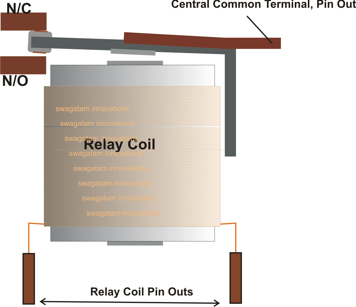
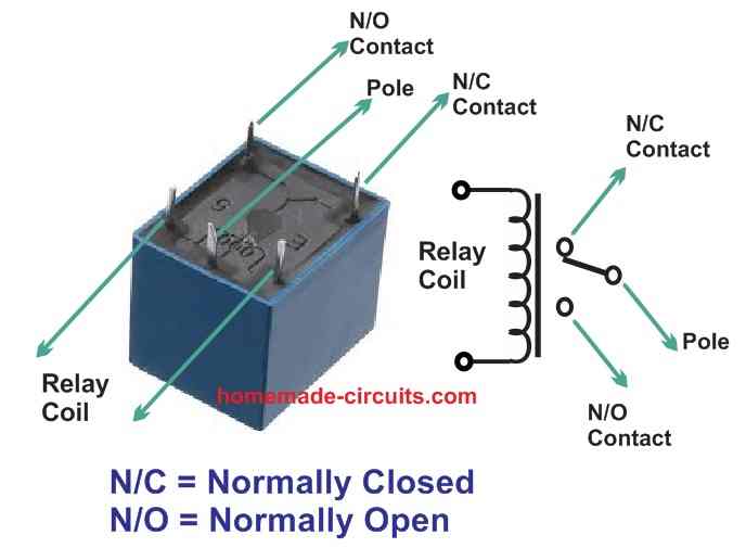
- A relay mechanism basically consists of a coil and a spring loaded contact which is free to move across a pivoted axis.
- The central pole is hinged or pivoted in such a way that when the relay coil is powered with voltage, the central pole joins with one of the side terminals of the device called the N/O contact (Normally Closed).
- This happens because the pole iron gets attracted by the relay coil electromagnetic pull.
- And when the relay coil is switched OFF, the pole disconnects itself from the N/O (Normally Open) terminal and joins itself with a second terminal called the N/C contact.
- This is the default position of the contacts, and happens due to the absence of an electromagnetic force, and also due to the spring tension of the pole metal which normally keeps the pole connected with the N/C contact.
- During such switch ON and switch OFF operations it switches from N/C to N/O alternately depending upon the ON/OFF states of the relay coil
- The coil of the relay which is wound over an iron core behaves like a strong electromagnet when a DC is passed through the coil.
- When the coil is energized the generated electromagnetic field instantly pulls the nearby spring loaded pole metal implementing the above explained switching of the contacts
- The above movable spring loaded pole inherently forms the main central switching lead and its end ts terminated as the pinout of this pole.
- The other two contacts N/C and the N/O form the associated complementary pairs of relay terminals or the pin outs which alternately get connected and disconnected with the central relay pole in response to the coil activation.
- These N/C and N/O contacts also have end terminations which move out of the relay box to form the relevant pinouts of the relay.
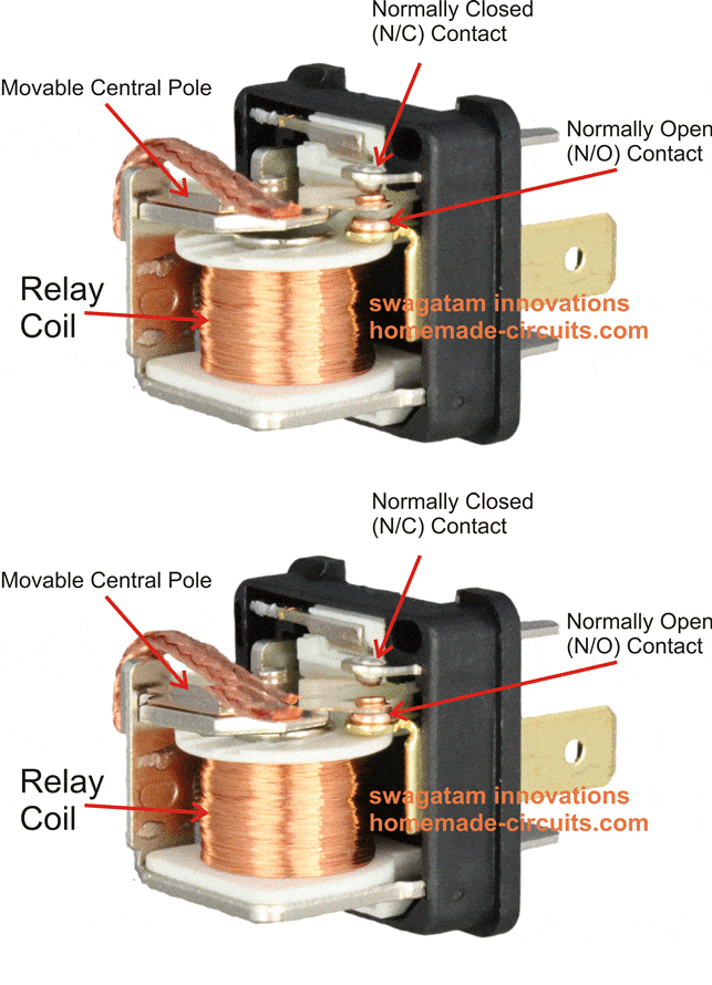
The following rough simulation shows how the relay pole moves in response to the electromagnet coil when switched ON and OFF with an input supply voltage. We can clearly see that initially the central pole is held connected with the N/C contact, and when the coil is energized, the pole is pulled downwards due to the electromagnetic action of the coil, forcing the central pole to connect with the N/O contact.
Video Explanation
Thus basically there are three contact pinouts for a relay, namely the central pole, the N/C and the N/O.
The two additional pinouts are terminated with the coil of the relay
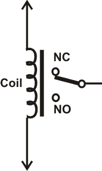
This basic relay is also called a SPDT type of relay meaning single pole double throw, since here we have a single central pole but two alternate side contacts in the form of N/O, N/C, hence the term SPDT.
Therefore in all we have 5 pinouts in an SPDT relay: the central movable or switching terminal, a pair of N/C and the N/O terminals and finally the two coil terminals which all together constitute a relays pin outs.
How to identify Relay Pinouts and Connect a Relay
Normally and unfortunately many relays don’t have there pinout marked, which makes it difficult for the new electronic enthusiasts to identify them and make these work for the intended applications.
The pinouts that needs to be identified are (in the given order):
- The coil pins
- The Common Pole pin
- The N/C pin
- The N/O pin
The identification of a typical relays pinouts may be done in the following manner:
1) Position the multimeter in the Ohms range, preferably in the 1K range.
2) Begin by connecting the meter prods to any of the two pins of the relay randomly, until you find the pins which indicate some kind of resistance on th meter display. Typically this may be anything between 100 ohm and 500 Ohm. These pins of the relay would signify the coil pinouts of the relay.
3) Next, follow the same procedure and proceed by connecting the meter meter prods randomly to the remaining three terminals.
4) Keep doing this until you find two pins of the relay indicating a continuity across them. These two pinouts will be obviously the N/C and the pole of the relay, because since the relay is not powered the pole will be attached with the N/C due to internal spring tension, indicating a continuity across each other.
5) Now you need to simply identify the other single terminal which may be oriented somewhere in across the above two terminals representing a triangular configuration.
6) In most cases the central pinout from this triangular configuration would be your relay pole, the N/C is already identified and therefore the last one would be your relay's N/O contact or pinout.
The following simulation shows how a typical relay may be wired with a DC voltage source across its coils and a mains AC load across its N/O and N/C contacts
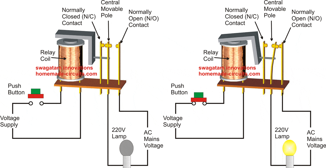
These three contacts may be further confirmed by powering the relay coil with the specified voltage and by checking the N/O side with the meter for a continuity..
The above simple procedure could be applied for identifying any relay pinout which may be unknown to you, or unlabelled.
Now since we have thoroughly studied how a relay works and how to identify the pinouts of a relay, it would be also interesting to know the details of the most popular type of relay which is mostly used in small electronic circuits, and how to connect it.
If you want to know how to design and configure a relay driver stage using a transistor, you can read it in the following post:
How to make a transistor relay driver circuit
A Typical Chinese Make Relay PinOuts
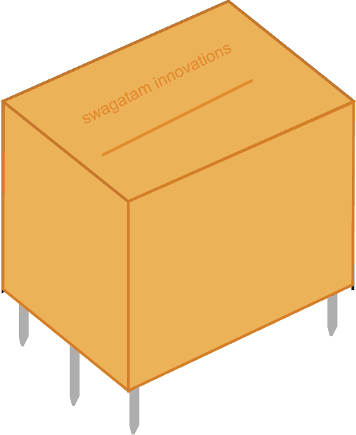
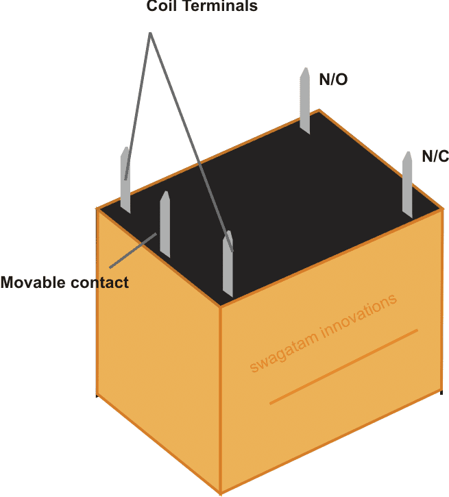
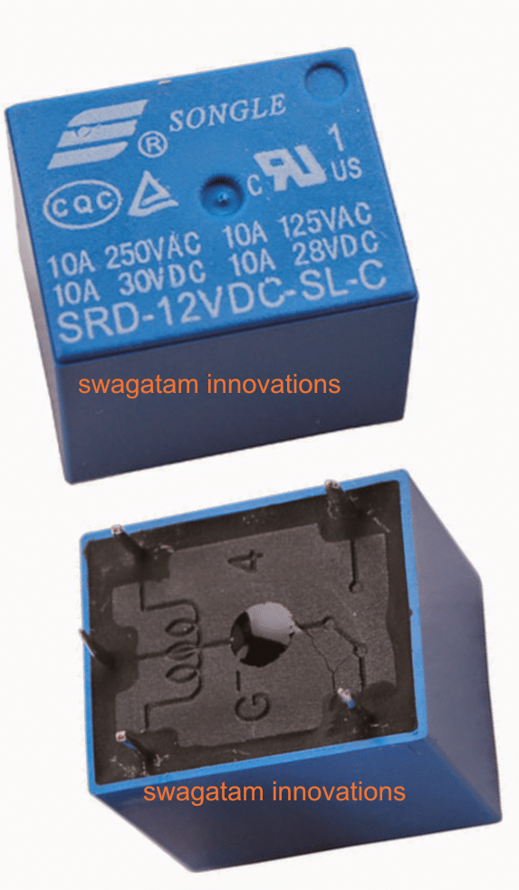
How to Wire Relay Terminals
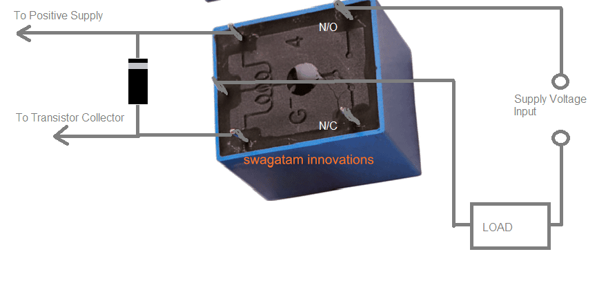
The following diagram shows how the above relay may be wired with a load, such that when the coil is energized, the load gets triggered or switched ON through its N/O contacts, and through the attached supply voltage.
This supply voltage in series with the load may be as per the load specifications. If the load is rated at DC potential then this supply voltage could be a DC, if the load is supposed to be an AC mains operated then this series supply could be a 220V or 120V AC as per the specifications.
Why is a Diode so Crucial across a Relay Coil
Whenever a relay is used in a circuit, you might have noticed a rectifier diode or a capacitor compulsorily connected parallel to the relay coil.
This diode is called the flyback diode or the freewheeling diode. It is basically introduced to protect the driver transistor from the dangerous reverse back EMF of the relay coil.
You might have wondered, why is a diode always seen across a relay coil? The following section explains why a flyback or a freewheeling diode is so crucial across a relay coil.
The answer lies in the fascinating yet a potentially destructive property of inductors.
We know that, just like capacitors inductors also store electric current (DC) inside its winding. Larger the winding, larger the amount of DC voltage its stores.
A relay coil is also an inductor which has a significantly high number of turns in its winding, and therefore its capacity to store a DC voltage is proportionately huge.
When the relay transistor is switched ON, the relay also switches ON, and it stores a calculated amount of DC voltage within its winding.
Now, as soon as the transistor is switched OFF, the potential across the relay coil is removed. In this situation, the DC voltage stored inside the relay coil has to escape somehow. It tries to discharge through anything that's connected with it. This is known as the relay reverse back EMF, which may have a reverse voltage that's many times larger than the actual DC voltage fed to the relay coil.
Since the driver transistor is connected with the relay, this large reverse EMF tries to force through the transistor emitter/collector. The word "reverse" is used because this back EMF is negative in polarity. Being negative in polarity this back EMF tries to force through the emitter towards the collector, causing an instant damage to the transistor.
In order to neutralize the above reverse back EMF a flyback diode or a freewheeling diode is always connected across a relay coil. This diode can be a simple 1N4007 diode for most of the relays (upto 30 amps).
As long as the relay remains switched ON through the driver transistor, the diode remains negatively biased and has no effect on the operation of the relay. However, when the relay is switched OFF, the diode becomes forward biased for the reverse EMF kicking out from the relay coil.
This back EMF now finds an easy path through the forward biased diode and short circuits through the diode. In this way the dangerous relay coil reverse EMF is neutralized and short circuited through the diode which totally safeguards the driver transistor from any possible damage.
If a diode is not available a high value electrolytic capacitor can be also used. The capacitor can function in the same way. It allows a reverse short circuit path for the back EMF and protects the transistor from getting damaged.
What if a Driver Transistor is not used and the Relay is Operated Directly from a Power Supply?
Even in this situation a freewheeling diode must be connected across a relay coil. Because the reverse back EMF from the relay coil may still have the potential to force enter the power supply or any associated circuitry and cause damage to the vulnerable electronic parts.
How to Calculate relay Flyback Diode
This may not be easy actually, because there are no easy formulas to calculate the relay flyback diode.
However, the rule of thumb is that, the reverse EMF current can be never higher than the actual current rating of the relay coil. Although the voltage could be many times higher.
A 1N4007 fits the bill for almost all relay driver applications (below 24 V and above 100 Ohm relays)
This is because a PIV of a 1N4007 is 1000 V and the current handling capacity is 1 amp. For most applications, the back EMF from a relay coil can never exceed the above ratings of the 1N4007 diode.
Even for a massive 12V 100 ohm relay, its coil current would be:
I = 12 / 100 = 120 mA. Thus the back EMF current will be much smaller than this. A 1N4007 will be perfectly able to handle this reverse current.


Questions & Answers
hello sir,
i came across someone’s designed relay board using octocouplers. in this they have attached two diodes, one from common terminal to nc terminal and other one from common terminal to no terminal. no is connected to -ve power supply so pside is connected to no, and nc is connected to +ve power suppy that is why n chalnnel is connected to nc. Do you know the reason of doing so?
Hello Divya,
The diodes could be transient type snubber diodes to suppress arcing across the relay contacts.
Sorry, I could not understand your following sentences, if possible please clarify more:
no is connected to -ve power supply so pside is connected to no, and nc is connected to +ve power supply that is why n chalnnel is connected to nc…
Hello Swagatam,
I hope you can advise me or assist me with my camper project(hobby) with the below scenario
I want to use a timer relay off delay for my camper safety which is, 2 cameras: one is working with the reverse wire trigger, and the second with the door opening and the output is a screen monitor to be delayed off for X (amount of time).
I have used 2 timer relays delay-off, each for a camera and the mentioned triggers but the problem is the power feeds back/ interferes with the other in the output and I can’t separate the camera triggers which should be on only when triggered either reverse or door opening separately.
How do I make this project work?
timer delay off= t= x (seconds/minutes delay off)
Regards
Markus
hi bro how are you
Hello Markus,
I will have to see the schematic diagram of your design to understand the problem.
So, if possible please send the schematic diagram to my email ID, I will try to figure it out for you.
Dear Sir,
I am confused as to whether I need a 12 volt 4 pin, or 12 volt 5 pin relay.
What I want to do is to add a switched 12 volt supply on my (2008) XT250 motorcycle to feed a dual USB plug plus at the same time a feed to a TomTom Rider 550 GPS.
I believe that I need to connect a relay to the registration rear plate light to turn on the relay when the bike key is turned on.
The YouTube video also suggested using a zip-tie to attach the relay to the bike frame. Is this OK or will there be too much vibration. i.e. what should I do?
Thank you.
Regards,
Robert.
Hi Robert,
You can use a 4-pin relay but a 5-pin is better because it is easily available, and having one N/C contact in spare won’t effect anything.
If you are worried about the vibrations, do not buy the small cube type relay with 400 ohm coil resistance, buy the one which has lower coil resistance maybe around 100 and 200 ohms. Lower coil resistance would mean larger coil current and more powerful contact activation which will not be affected by the vibrations.
Dear Sir,
1) Is a Narva 68028 suitable?
2) If not, what should I buy.
Thank you.
Robert, , and check whether it is affected by the vibrations or not.
I would suggest you to first try a standard
If yes only then you can look for other alternatives.
However the Narva 68028 is not suitable, because its rating is too high, which is not required.
Yes agreed so I revaluated what the circuit is doing.
At 3500 rpm there are 3 groups of 2 magnets rotating.
the Triger for the relay is hall sensor 180° apart under the coils of which only 2 are the Triger that open and close the Relay.
So at 3500 rpm the switching time is 10,500.
With 1 rpm the Switching Time/min is 3.
Gregg
OK, thanks for the clarification, understood now.
However, at this rate I don’t think the relays would last very long.
Yes agreed, somewhere below 3000 rpm maybe a comfortable region.
But for now I will try your homebuilt 12v ssr MOSFETs, the store bought ones just don’t work with my application.
Sure, you can try it. Let me know if you have any problems.
Hi Swagatam
I wanted to ask you about the Relay Data Sheet reference to:
Iam using the 3v relay
Operation Time 10msec Max.
Release Time 5msec Max.
Max. ON/OFF Switching
Mechanically 300 operation/min
Electrically 30 operation/min
My question is, am I to understand, the relay can open and close 300 times per min?
Hi Gregg,
Yes, if the datasheet says 300 operations per minute that means closing and opening 300 times. One close/open = one operation.
That’s what I thought also, but even in there data doesn’t make sense to me, and here is why.
Operation Time 10msec Max
Max. ON/OFF Switching
Mechanically 300 operation/min
Electrically 30 operation/min
There are 100 (10msec) per sec. And 6000 per min.
In my own experiments I am getting 21000/min ON/OFF operation Switching Time/min, before the relay gets kind of hot.
Thanks for your response.
Gregg Pierce
Your calculations look correct, but how did you check 21000/min ON/OFF operations? Because 21000 number is huge.
The datasheet could be suggesting the safest range of the operation, without causing considerable stress on the relay.
Swagatam
So I did some recalculations and testing with and without the load, the load being 10 to 12v.
every time the magnet passes the hall effect the relay opens and closes and with 6 magnets that is 6 operations per rotation. Also I took the shell off so I could better understand the relay workings. I could touch and hold it while in operation and a comfortable range for my purposes was 2200 to 2500 rpm.
probably not what the relay was designed for but for now it works me, till I can build a homebuilt ssr.
Thanks Gregg
Thanks Gregg, for updating the results. Glad it is working for you at the moment. Do let us know if you happen to test the results using an ssr.
This is very similar to my circuit, which I will try to explain the best I can. But my question was to the “stackoverflow” people was all I wanted to do was to replace the 5v mechanical relay with a 2N7000 homemade circuit or just buy one. They started asking alot of questions that I could not answer or have the time for.
Anyway here is my circuits, One to operate the coil to open the N/C contacts and a separate power source to drive the load.
I have through trial and error found this works for me. The coils which are 6ea placed 60 deg. apart in a circular fashion about 4″ apart on a 6″ board. The A144 hall sensors 6ea are placed inside the coils.
There is a small rotor made of plastic that hole the neodymium magnets 12ea 6ea on top and 6ea underneath also at 60deg apart like a sandwich. A simple motor so far.
The operation is this, I hand start the rotor and the magnets S pole rotates across the coil and the A144 hall sensors all at the same time but through experimentation I find i only need two of them which are 180deg apart. When the magnets pass the A144 hall sensors that opens the N/C contacts of the relay
So I know that motor can rotate faster with an mosfet, ssr, homemade circuit.
Thanks Gregg
Thanks for sharing your experience. Yes a MOSFET based relay is always better and more efficient than an electromechanical relay.
However, I could not understand your question, or the problem you are facing.
Simply, I guess my question is replacing the mechanical relay with a mosfet.
Currently, the one I’m using is the 2N7000.
I guess I should make a drawing and send it that would be more clearer.
I have an article on this subject which explains how to use MOSFETs to build solid-state relay, here’s the link:
https://www.homemade-circuits.com/12v-dc-solid-state-relay-ssr-100-amps/
The above concept is designed to work with DC supplies only.
However 2N7000 can handle only 200mA, so make sure to replace it with a higher rated one, depending on your load current spec.
Thanks Saad, Glad you found it useful.
Thank you, glad you liked it!
I want/need a relay that is normally closed. When power, 12V , is applied to the “trigger” the relay opens.
You can try the following schematic:
Can I make a toggle switch circuit with relay? I mean, By using just on/off (push button) switch to control LEDs? Ex. When I switch on a circuit, the LEDs stay lit even if I release my fingers from on/off switch and when I touch the switch again the LEDs will be turned off.
Yes you can, using the concepts explained in the following article:
https://www.homemade-circuits.com/build-these-simple-flip-flop-circuits/
I have a 5 pin relay which I would like to wire normally closed (Power to the instrument) and opened by applying a ground. Possible?
Yes, that’s possible. Use an NPN transistor to power the relay. Let the transistor be powered through a base resistor connected to the positive supply.
In this position grounding the transistor base will turn OFF the relay.
what is rectification failure relay, how it works and what are example of this?
thanks swagatam,
it is over now. Every thing is oky, the diagram illustrates the real function of a relay.
kind regards.
Godwin.
Thanks Godwin, Glad it helped!
hi, swagatam
The article was well understood. But my question is how does a relay sources a current in a circuit? As i, get you, expressed only in switching circuits.
thanks.
your friend in electronics.
Godwin.
Malawi.
Thank you Godwin,

The relay switches current and voltage through its contacts, as shown in the following GIF image:
That’s a good presentation
Thanks
Last two days I’m watching videos on youtube trying to understand the relay. Luckily I found your valuable post on the internet and I’m really benefited from your post here. Thanks for this post from you.
Thank you, and Glad you found the post useful!
Dear Sir,
What is the transistor and diode values and I want to use this open sliding gate (Ac motor) with Fingerprint(DC 12v) device so please tell me how can do it
Thanks
Hi Chandana,
For a relay the transistor can be a 2N2222, and the flyback diode across the relay coil can be a 1N4007 diode.