A PIR motion sensor alarm is a device which detects the infrared radiation from a moving human body and triggers an an audible alarm.
In this post I have explained 5 simple motion detector circuits using op amp and transistor. We also discuss the pinout details of the standard passive infrared (PIR) sensor RE200B.
We will Learn:
- How to use a PIR sensor device to Detect human body infrared.
- How to use a PIR module as a Security Burglar Alarm Circuit
- How to use a PIR to switch ON lights when a human presence is detected.
- How to apply a PIR to detect an object in industrial applications
The first circuit uses an op amp, while the second design works with a single transistor and relay for detecting the IR radiation from a moving human body and activating the a relay activated alarm.
What is a PIR
PIR is the acronym for Passive Infra Red. The term "passive" indicates that the sensor does not actively take part in the process, meaning it does not itself emit the referred infra red signals, rather passively detects infrared radiations emanating from warm blooded animal in the vicinity.
The detected radiations are converted into an electrical charge proportional to the detected level of the radiation. This charge is then further enhanced by the built-in FET and fed to the output pin of the device which becomes applicable to an external circuit for further amplification and for triggering the alarm stages.
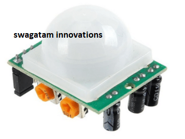
PIR Pinout Details
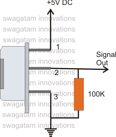
The image shows a typical PIR sensor pinout diagram. It's quite simple to understand the pinouts and one may easily configure them into a working circuit with the help of the following points:

Technical Specifications of the PIR Sensor
- Sensor Type: Passive Infrared (PIR) sensor element.
- Sensitive Area: 2 elements.
- Spectral Response: 5 µm to 14 µm (infrared wavelength range).
- Output Voltage: Millivolt-level signal (0.4 mV pp typical).
- Offset Voltage: 0.1 volts (typical).
- Supply Voltage: 2 to 15 volts.
- Operating Temperature: -30°C to +70°C.
- Field of View (FOV): 138°.
Connections:
- Pin 1: Drain.
- Pin 2: Source.
- Pin 3: Ground.
Test Conditions for Output Voltage:
- Supply voltage: 5 volts.
- 100k load resistor from pin 2 to pin 3.
- Infrared source: Hand moving 6 inches from the sensor.
Pinout Details
As indicated in the following diagram, PIN#3 of the sensor should be connected to the ground or the negative rail of the supply.
Pin#1 which corresponds to the "drain" terminal of the dvice should be connected to the positive supply, which must be ideally a 5V DC.
And pin#2 which corresponds to the "source" lead of the sensor must be connected to ground via a 47K or 100K resistor. This pin also becomes the output pin out of the device and the detected infrared signal is carried forward to an amplifier from pin#2 of the sensor.
1) PIR Human Movement Detector Circuit using Op Amp

In the above section I have explained the datasheet and the pinouts of a standard PIR sensor now lets' move on and study a simple application for the same:
The first PIR circuit diagram for sensing moving humans is shown above. A practical implementation of the explained pin-out details can be witnessed here.
In the presence of a human IR radiation, the sensor detects the radiations and instantly converts it into minute electrical pulses, enough to trigger the transistor into conduction, making its collector go low.
The IC 741 has been set up as a comparator where its pin#3 is assigned as the reference input while pin#2 as the sensing input.
The moment the collector of the transistor goes low, the potential at pin#2 of the 741 IC becomes lower than the potential at pin#3. This instantly makes the output of the IC high, triggering the relay driver stage consisting of the another BC547 transistor and a relay.
The relay activates and switches ON the connected alarm device.
The capacitor 100 uF/25 V makes sure that the relay remains ON even after the PIR is deactivated possibly due the exit of the radiation source.
The PIR device discussed above is actually a core sensor and can be extremely sensitive and difficult to optimize. In order to stabilize its sensitivity the sensor should be suitably enclosed inside a Fresnel lens cover, this will additionally enhance the radial range of the detection.
If you are unsure about using an uncovered PIR device, you can simply go for a readymade PIR module with a lens and other enhancements, as described below.
Calculations
PIR Sensor Output Voltage Range:
The PIR sensor (RE200B) gives out about 0.4 mV (peak-to-peak) when it senses movement.
To connect it to the op-amp comparator you might need to boost this signal to a level that can be detected using a BJT preamplifier.
If we use an amplifier that increases the signal by 1000 times, the new amplified signal will be:
Vout_PIR = 0.4 mV × 1000 = 0.4 V (peak-to-peak).
Comparator Circuit Design:
Use an op-amp like LM358 as a comparator.
Reference Voltage (Vref): Choose a reference voltage slightly higher than the ambient noise level. For example:
Vref = 0.2 V.
Connect the amplified PIR sensor output to the non-inverting input (V+) of the op-amp.
Apply the reference voltage to the inverting input (V-).
Comparator Output Logic:
When V+ > V- (PIR detects motion), the op-amp output goes high (Vout = Vcc).
When V+ < V-, the op-amp output goes low (Vout = 0).
Relay Triggering:
Use the op-amp output to drive the relay through an NPN transistor (e.g. BC547).
Calculate the base resistor (Rb) for the transistor.
Assume:
- Relay coil voltage (Vrelay): 12V.
- Relay coil current (Irelay): 50 mA.
- Transistor current gain (hFE): 100.
- Op-amp output voltage (Vop): 5V.
Base current (Ib):
Ib = Irelay / hFE
= 50 mA / 100
= 0.5 mA.
Base resistor (Rb):
Rb = (Vop - Vbe) / Ib
= (5 - 0.7) / 0.5 mA
= 4.3 kΩ.
Choose Rb = 4.7 kΩ (nearest standard value).
Power Supply Requirements:
PIR Sensor: 5V supply.
Op-Amp: 5V supply (ensure it is within the op-amps operating range).
Relay: 12V supply (use a separate supply with a flyback diode across the relay coil to protect against voltage spikes).
Flyback Diode:
Use a diode like 1N4007 across the relay coil.
Ensure the diodes reverse voltage rating is greater than the relay supply voltage (e.g 12V).
2) PIR Motion Detector and Security Alarm Circuit
The following PIR motion sensor circuit can be easily built using the following basic set up and applied as a anti-theft alarm circuit.
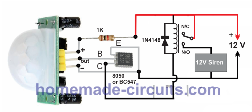
As the figure shows, the PIR only requires a single 1K resistor, transistor and a relay to be configured externally. The siren can be either built at home or purchased ready made.
The 12v supply can be from any ordinary 12V 1 amp SMP circuit.
Video Demo
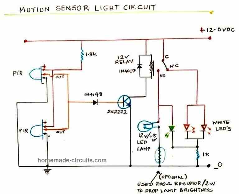
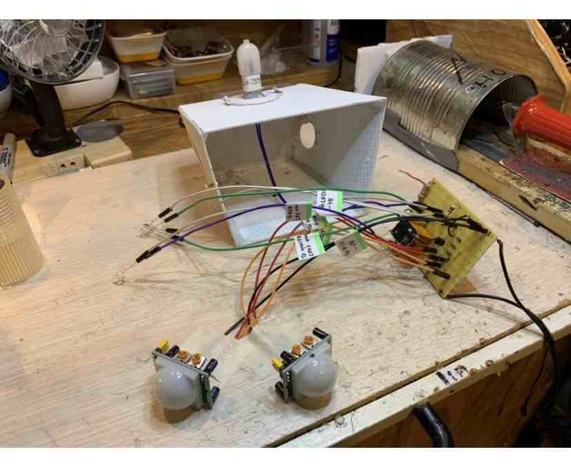
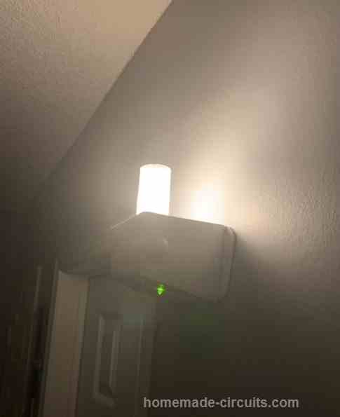
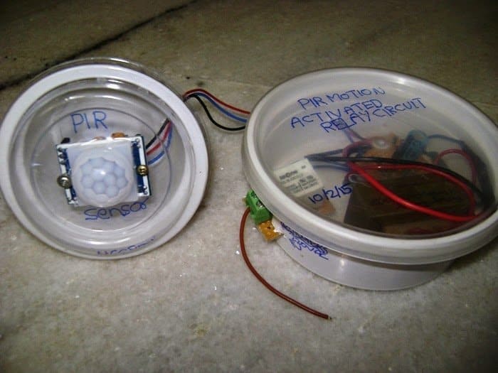
3) Human Presence Detector using Two PIR Modules
The above explained PIR motion detector circuit can be also built using 2 PIR sensors in parallel for a 360 degree human presence detection.
This idea was tried and tested successfully by Mr. V.
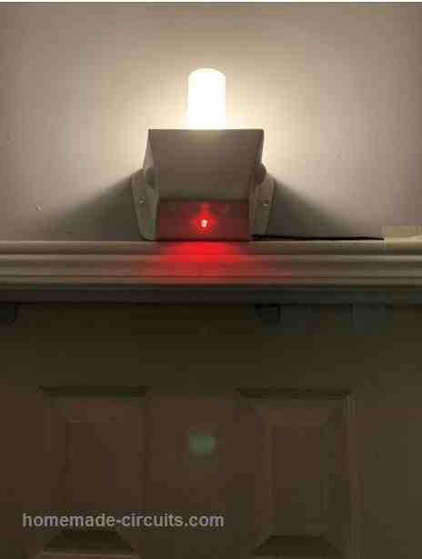
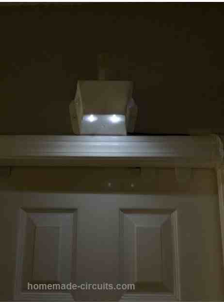
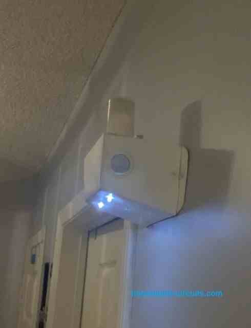
Th device was installed above one of the door entrances for illuminating the passage automatically whenever a human approach was detected by the PIR sensors.
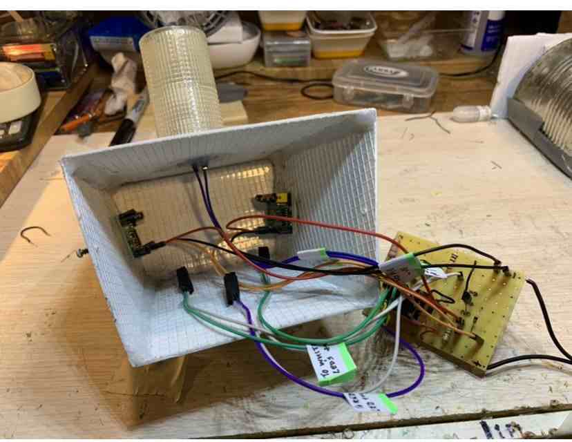
The following amazing circuit diagram and the tested prototype images were contributed by Mr. V.
Let's have a look at them.
How to increase the Range of the PIR
The following information was sent by Mr. V. Hope this will help the users to adjust the range of the PIR to its maximum capacity.
Just this bit of info, I was playing around with the PIR Sensitivity Potentiometer and I realized it practically that if you turn the adjustment clockwise the sensitivity & Range increases, unlike what is given in the product description, it says turn Counterclockwise for max sensitivity. I tried it gradually in different positions & with it turned to about the 3 O’clock position, clockwise I get a Range of about 16 feet. I did not go max.
However the PIR should not be in an area with very bright light as it becomes unstable, it should be guarded or shaded from bright light.
Hope this was helpful,I did a check on 5 pieces & all responded the same way, I was very disappointed with the Range earlier now I’m happy. The timer pot is good, keeps to time set.
4) Another Simple PIR Based Alarm Circuit
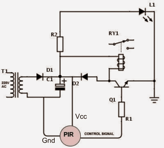
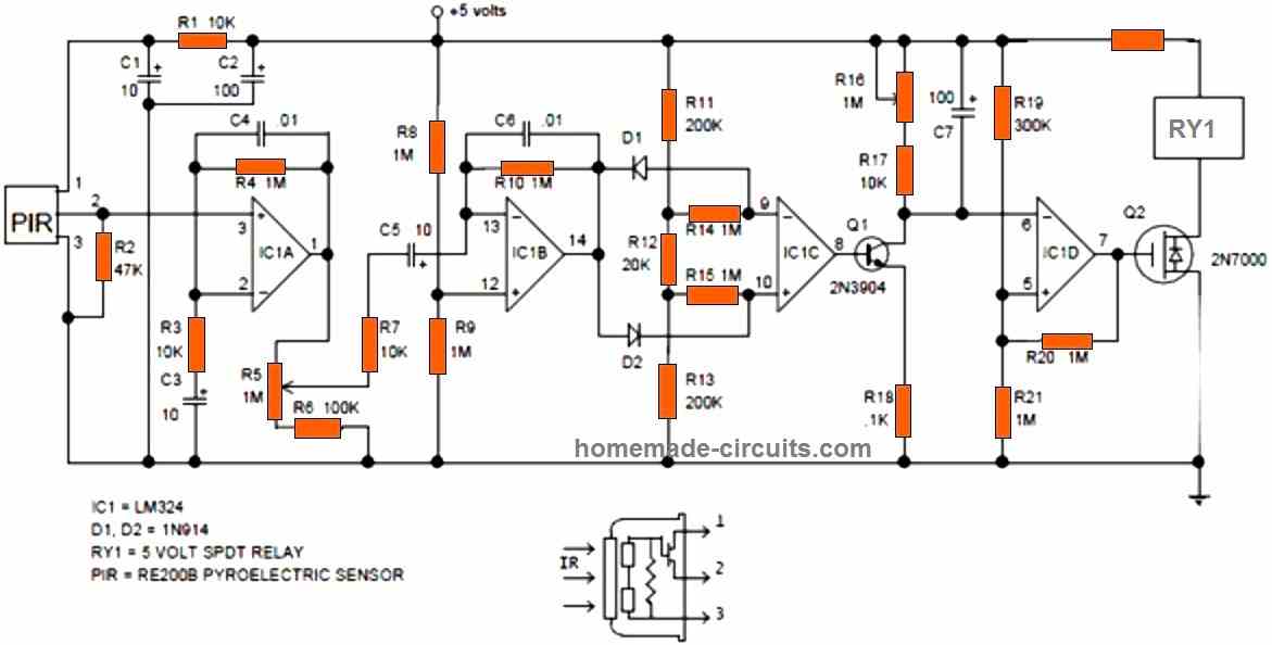
The fourth idea below explains a simple PIR motion detector alarm circuit which can be used for activating lights or an alarm signal, only in the presence of a human or an intruder.
How it Works
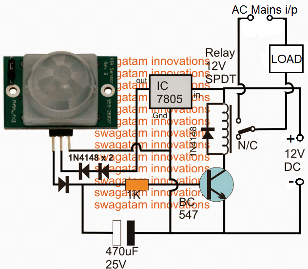
Here is a simple circuit that activates a relay alarm when a living being (a human) is detected by the PIR sensor. Here PIR stands for Passive Infrared sensor. It doesn’t produce any infrared radiations to detect the presence of a living being but on the other hand it detects the infrared radiations released by them.
This circuit uses a HC-SR501 IC which is the heart of the circuit. Initially when the moving object is detected by the sensor, it produces a small signal voltage(usually 3.3 volts) which is fed to the base of the transistor BC547 through a current control resistor and hence, its output goes high and it switches the relay on.
A more Comprehensive Diagram can be Visualized below:
Relay Wiring
This relay can be configured to be used with a electrical bulb or a tubelight, night lamp or anything else that works on 220VAC.
This circuit is mostly used in gardens, so that at night, when we go for a walk in the garden, the circuit switches on a light automatically and it remains lit until we are in the sensor’s vicinity and it gets turned off when we move away from that place and hence reducing the electricity costs.
Here’s a back view of the sensor HC-SR501…
HC-SR501 Pinouts
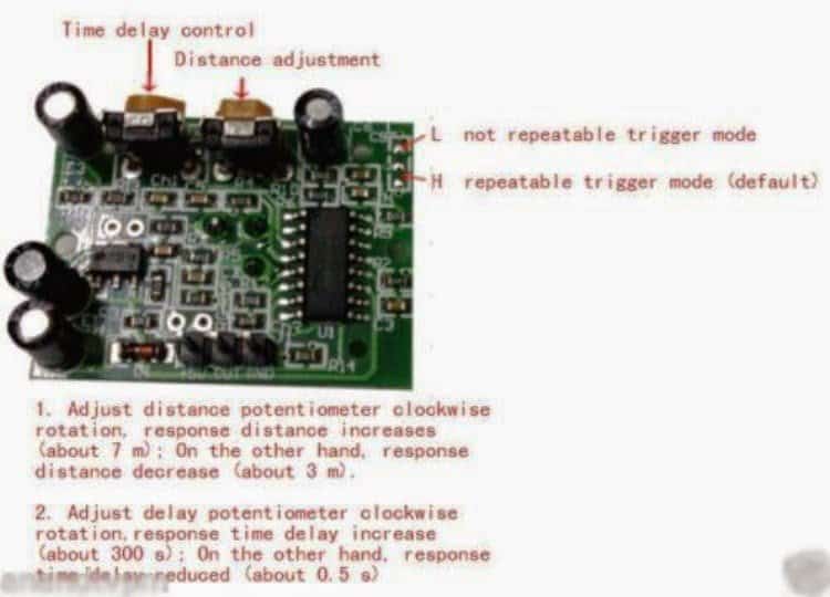
PIR Sensor Front View:
The sensor consists of two preset resistors which can be used to control the delay time and sensing range.
The delay potentiometer can be adjusted to decide the time for which light remains on.
The sensor when purchased, it comes with the default mode ‘H’ which means that the circuit switches on the light when somebody moves within the zone and it remains on for preset time and after the preset time lapses, if the sensor could still detect motion, it does not switch the light off in the absence of a moving target, it switches off the light.
Here are the technical details of the sensor HC-SR501
- Working voltage range: 4.5VDC to 12VDC.
- Current Drain: <60uA
- Voltage output: 3.3V TTL
- Detection distance: 3 to 7 metres(can be adjusted)
- Delay time: 5 to 200 seconds(can be adjusted)
One of the disadvantages PIR sensors is that its output goes high even when a rat or a dog or some other animal moves in front of it and it switches on light unnecessarily.
In cold countries, the sensor’s sensing range increases. Due to low temperature, infrared radiations released by humans travel more distances and hence causing unnecessary switching of lights.
If installed in backyards, there are chances of activating of light when a car passes by because the radiations emitted by hot engine of car fools the sensor.
PARTS LIST:
- D1, D2 - 1N4007,
- C1- 1000uf, 25V,
- Q1 - BC547,
- R1 - 10K,
- R2 - 1K,
- L1 - LED(green)
- RY1 - Relay 12V
- T1 – Transformer 0-12V.
After completing the construction of the circuit, enclose it in a suitable casing and use a separate casing for the sensor and connect the sensor to circuit using long wires so that you can place sensor at the place you wish like in a garden and circuit will be inside so that the circuit is protected from weather.
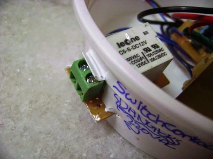
And remember to use a separate PCB for relay.
Also, don’t forget to use a suitable relay with correct current and voltage rating. You can use a terminal block which connects to the relay’s switching contacts, and arrange it as shown in image so that you can change the electrical device connected to relay contacts easily.
Usage of this sensors save electricity to great extents. It could reduce your electricity bills too!
“PLEASE SAVE THE POWER FOR THE NEXT HOUR!”
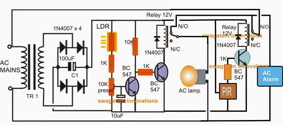
If the above PIR moving human detector design is intended to be used with an alarm and a lamp such that both the loads operate during night but the alarm only during day, then the diagram may be modified in the following manner. The idea was suggested by Mr. Manjunath
5) Industrial Application
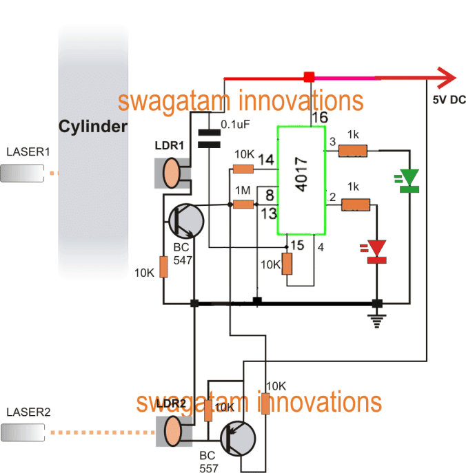
The 5th circuit diagram below shows an industrial motion sensor circuit using a couple of LDRs, an IC and a few other passive components. The circuit senses the movement of a cylinder illuminating the appropriate LEDs for the required detection. The idea was requested by Mr.Hasnain.
Technical Specifications
I have sent you request on Google account, i am not sure that you got my messages or not, so i am sending you my problem here again, please help me out i shall be very thankful to you, i hope you will understand my problem and solve it...
sir it is related to motion sensing, and i have no knowledge about sensors, that which type i should use..problem : there are two levels, ( level means height), level A, and level B. height A > height B.i want to use sensors at these levels, so from now i will say sensor A and sensor B..
i have two indication lights RED and GREEN there is a cylinder that moves from up to down and then down to up and so on..first it will move from up to down and will come in front of sensor A.
( at this time RED light should turn ON and GREEN turn OFF) and moving downward cylinder will come in front of sensor B.
( this should make no difference, i,e RED should remain ON, and GREEN should remain OFF ).
then cylinder will start moving upward, first it will move away from sensor B.
( at this time RED should turn OFF and GREEN turn ON), then moving upward cylinder will move away from sensor A,
( this should make no difference. i,e RED should remain OFF and GREEN should remain ON)..then again repeat.
The Circuit Design
The proposed idea is quite straightforward and can be understood with the following points:
When power is switched ON, the IC is reset through the 0.1uF capacitor ensuring the green LED illuminates first.
At this position both the sensors sensorA (LDR1) and sensorB (LDR2) are able to receive the lights from the relevant laser beams focused at them.LDR1 switches ON BC547 transistor while LDR2 does the same for BC557 and keeps it triggered.
Due the above actions the transistor BC557 passes the supply voltage to pin#14 of the IC. However since LDR1 ad BC547 are also conducting this potential gets grounded, and the net potential at pin#14 remains at logic low or zero.
Now as the cylinder lowers and comes in front of LDR1, it blocks the beam making LDR1 resistance high, shutting OFF BC547.
This allows the voltage from the BC557 to hit pin#14 producing a forward sequence at the output of IC which results in illuminating the red LED and shutting off green LED.
The cylinder continues its downward motion and comes in front of LDR2 blocking its beam and lowering its resistance, this stops the transistor from conducting such that the potential at pin#14 of the IC is again switched back to zero, however this action does not effect the IC since it's specified to respond only to positive pulses.
Next, the cylinders reverts and starts moving upwards and in the course unblocks the LDR2 beam allowing the BC557 to conduct, and yet again the positive pulse from the transistor is allowed to hit the IC pin#14 resulting in the restoration of the previous situation i.e. now green LED illuminates and the RED shuts off.As the cylinder moves past LDR1, BC547 also switches ON, but produces no effect due to the same reasons as explained above.
The above motion detection cycle keeps repeating in response to the specified cylinder movement.
Circuit Diagram
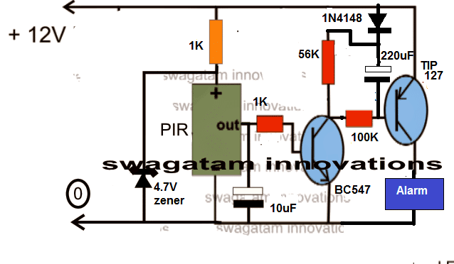
PIR Security Alarm with Delay Effect
When the PIR is triggered, the BC547 switches ON which in turn prompts the TIP127 to switch ON. However, due to the presence of the 220uF capacitor the base emitter voltage of this PNP transistor is unable to attain the required 0.7V quickly, and the LED does not light up until the 220uF is fully charged.
When the PIR is switched OFF, the 220uF is able to quickly discharge through the 56K resistor, rendering the circuit in a standby position quickly. The 1N4148 diode ensures that the circuit works only as a delay ON PIR circuit and not as a delay OFF.


Questions & Answers
Dear Mate need a motion detector circuit unit outside in the drive way and alam inside the house using 12V battery and must be able to detect 40m, please need a circuit diaghram?
Hi Hendrik,
I guess the following concept should be able to fulfill your 40 meter distance specification:
https://www.homemade-circuits.com/how-to-connect-and-use-rcwl-0516-microwave-sensor/
Make sure to put an extra long antenna to the existing one.
If it doesn’t solve your requirement, in that case you can try the industrial grade Doppler radar modules like the CDM324
Can’t wait to say how grateful and excited stumbling on to this site has made me. I will make a time to return as I have an allied question: How does the wireless connection and message encoder system work for wireless PIR’s when there is more than one to learn?
Thank you for your feedback, I am glad this site helped you, however currently I have no information regarding How the wireless connection and message encoder system work for wireless PIR’s.
I will keep looking for it and update in case I find anything useful….
Hi,
I have an RE200B PIR sensor, and I was able to get it working by connecting a 1nF capacitor and a 100K ohm resistor. I also have a transistor and an op-amp for amplification, but I’m finding it difficult to design an amplifier circuit that properly amplifies the output from my RE200B sensor.
Since this is my graduation project, understanding how to build the amplifier circuit would make a huge difference. Is there a tutorial video that explains how to do this on a breadboard?
Any guidance would be greatly appreciated!
Hi,
A single BJT should be enough to amplify the RE200B sensor output for the IC 741. If you are still having difficulty in toggling the BJT, you can modify the BC547 with two BJTs configured in Darlington mode and check the response.
Can you give me a circuit diagram for it please
You can try it in this way:

Hey sir, greetings from Brazil! I have a question regarding the first section, but first a bit of background. I am by no means an engineer, I am simply a college cs student, so my knowledge of electrical engineering is very, very, limited. I have bought a PIR sensor (specifically the ZRE200GE but without the fresnel lens) and I have bought a few op amps and transistors for this project. My goal is just to illuminate the shoe room of my house, so it doesn’t have to be anything fancy. My questions are: can I complete this project without using a fresnel lens since accuracy is not of the highest order? How would I go about connecting a PIR sensor to an Arduino? Would I only need the PIR sensor, op amps, transistors, and wires?
Thanks again for your time, you must be a very busy man!
Hey Eduardo,

Yes you can try the following design without the fresnel lens, although in that case the circuit could become too sensiitive.
If you are having the correct Arduino code then you can use it with the sensor without the lens. In that case the opamp circuit might not be needed.
Just always make sure to connect a high value resistor of 2k—-10k in series with the (+) input of the sensor, to limit the current to the sensor and prevent false triggering of the circuit.
Hi Swagatam,
I found a mistake on my PCB. It is now working fine. Thanks for your quick response!
That’s good Norman, Glad it is solved now!
Hi Swagatam,
I have a 501 PIR circuit that turns on a 5v cooling fan. The cooling fan is actually turned on and off by a 555 monostable. I bread boarded the circuit and it works perfectly. I PCB’d it and the PIR never turns off. Any ideas as to why the PIR never turns off. I tested two different 501 PIRs on the bread board and both work perfectly. When installed on PCB they never turn off.
Hi Norman,
Please try adding a 1k resistor in series with the Vcc supply of the PIR and check the response.
Let me know if it works or not?
Dear Sir , You always deserve the thumbs up for very fast and correct reply. I keen to know that your circuit design:
2) PIR Motion Detector and Security Alarm CircuitUpper of that page . Is it possible to remove relay and directly connect a 12v Siren here to make this circuit cost Savings .
Thank you Jobayer,
Yes, that’s possible. You can replace the BC547 transistor with a TIP122 and activate a siren directly between its collector and the positive supply.
dear sir…
i was trying to replace variable resister on PIR module HC-SR501 for distance….unfortunattly silver coated is removed and unable to find path…please guide me where i can connect VR for diatance
thanks
Hi Ghulam, can you please check the PCB and tell me where the 3 contacts of the VR are leading to, for example IC inputs, transistor base, ground or Vcc etc?
sir i tried but couldnot found the path, timer VR is ok, only distance VR coated removed,
Sorry, but without knowing the components associated with the VR it is impossible to tell the exact connections of the VR tracks.
Hello, how to adjust circuit no.1 so that the PIR only responds at night?
Replace the IC741 pin2 resistor with 100k resistor, replace IC741 pin3 preset with a 100k preset.
Connect an LDR between pin3 and ground of the IC741.
If you find the circuit too sensitive consider reducing the 100k resistor value across the PIR sensor pinouts.
Hi sir Salute to your spirit
Sir I have 36 solar panels and recently there are solar panels robberies in our area so I want you to take out your valuable time and set up a circuit for me which is perfect in all respects. And perfect for thieves of all mindsets
I eagerly await
I Will do
Sorry for weak English
Thank you Swasti,
There are a few options, such as vibration sensor, motion sensor, and PIR sensor.
You have posted another comment on another post, so I will try to specify the one which is more appropriate under that comment.
Sir engineer Swagatam
I recently purchased a PIR sensor. when I searched for a circuit diagram on your website to find and assemble a circuit to alert me if a cat comes down from the tree into the yard where my pigeons live, I noticed that it’s shape, and all components are exactly the same as the one that you have published a very good article about: SR501 ( https://www.homemade-circuits.com/pir-sensor-datasheet-pinout-specification-working/); along with a circuit diagram, and that you have referred one of your visitors to the second circuit which is composed of one S8050 or BC547 transistor and a relay. A customer reported that it works with 5 to 12 volts but it is better to use 5 volts.
would you please confirm if this circuit would be suitable for my needs?
yours truly
Ersa
Thank you Ersa,

I guess you are referring to the following design:
I have tested this circuit myself thoroughly with 12V and did not find any problems with a 12V DC and a 12V relay.
However you can also try a 5V supply with a 5V relay, it should still work.
Just be careful with the pin connections of the transistor since 8050 pinouts are exactly opposite to a BC547 pinouts.
Thank you very much dear Swagatam. I hope it will react to the Cat the same as human beings. God bless you.
You are most welcome Ersa, Yes a cat should be detected since a cat also radiates body heat in the form of infrared emission, just like a human being.
Dear Sir Swagatam
Hello. Hope you are healthy. It is working well. Thank you for publishing this excellent circuit.
Truly yours
Ersa
Thank you Dear Ersa, for updating the information. I am so glad it is working for you. Please keep up the good work.
Hi Swagatam,
In my house, I have installed the HC-SR501 PIR modules with a relay modules to activate the lights during the motion detection in 10 different places in my house. After some days/months, I noticed the false trigger in some of the PIR modules modules. Some modules are keep on fluctuating between high and low, and some modules are always in high only. Then I replaced them with the new PIR modules and the cycle repeats the same like working good for some days/months and giving problem after that. Am not able to find out the solution for this problem. So now I decided to make a own circuit with IC555 as monostable (for timer) integrating with core PIR D204S. But am not able to integrate PIR D204S with IC555 to activate the relay. So I tried your first circuit from the above but no luck. And also Am confused on choosing the correct core PIR for my circuit.
1. Kindly suggest which core PIR from the below three I can use for my purpose, or suggest me a correct one from your side.
D204S
PIR Sensor G2x2
D204B
2. How to integrate the core PIR with IC555 monostable to activate the relay.
Kindly help.
Hi Sriram,

Please do not try the PIR without the fresnel lens it will give you lots of problems, because it is highly sensitive and can produce erratic results without the lens. Moreover the core PIR module cannot be integrated with a 555 monostable directly. You will need the following elaborate circuit to make it work correctly.
Instead you can make the following circuit, this has been thoroughly tested by me, and it works without any issues.:
Please note that an 8050 has been in the schematic, if you BC547 the emitter collector pin connections will be opposite
Thanks you for the suggestion. Will try on that.
No problem.
Dear Mr. Swagatam!
I have a PIRMINI-SR505 sensor. I need a circuit which give a short pulse anytime when anybody approach the sensor. The length and the frequency of the pulse is not important. I want to use this pulse to reset a counter or drive a Latch.
I hope you can help me.
Thanks.
Your Hungarian reader: Federics István.
Thank you Federics,
You can try the following design, it should do the job for you.
One further Question, What is the number of the Ready Made PIR module in No 2 so that I can locate it to purchase several’
Many thanks for your help
Athol
The number is HC-SR501
Can I use your first or other circuits in the following application. Sensor to turn on a low voltage motor then turn it off when the person has walked passed and continue in this manner as more people pass by. This is in a daylight situation only.
Yes, you can do it.
I would recommend circuit 2) which is a fully tested:
Très fantastique. Merci infiniment pour tes efforts. Ahmed du Maroc
You are most welcome!
Your tutorial is fantastic.i enjoyed the PIR circuits detailed diagrams
Thank you!!! Glad you found it helpful.
where can i find a li-ion battery charger circuit
12 volt dc battery
5 to 8 amp charging with auto cutt off
You can refer to the last relay circuit from the following article. Replace the relay with a 12V relay, and use a supply Dc that suits your battery.
https://www.homemade-circuits.com/usb-automatic-li-ion-battery-charger/
Dear Mr. Swagatam,
Thank you so much for these innovative tutorials. I’ve a critical interest ( obsession) in electricity. I want to learn from the scratch. May you please give me your contact WhatsApp or. And also I was wondering that from where do you get those electric circuit components, I meant , for instance, Like the resistors, PIR, LED etc.
Many Thanks, your response has been appreciated very much!
Thank you Emmanuel,
I understand your requirement. If you have any queries or doubts you an ask them through comments, I will try to solve them for you.