The following email discussions were sent to me by Mr John Sweden who is one of the avid readers of this blog, here he explains about an USB isolator device, and how it may be incorporated while using an oscilloscope with a PC, in order to safeguard the oscilloscope and the test circuit from accidental high volatges. I have explained more.
Circuit Concept#1
Some time ago I purchased a Digitech 40MHz Dual Channel USB Oscilloscope that i would now like to learn to use with a PC via USB.I had heard that one must use extreme caution when placing the oscilloscope probe earth of this (and any) oscilloscope on the test circuit if that test circuit is also brought to mains earth potential by plugging it in to a USB port to power it.A wrong move could zap the test circuit and possibly the oscilloscope 🙁 A video by Dave of EEV Blog explains the dangers more clearly than I can.One answer to this problem would be to place a USB Isolator between the usb input of the test circuit and the PC. An example of such an isolator is shown here: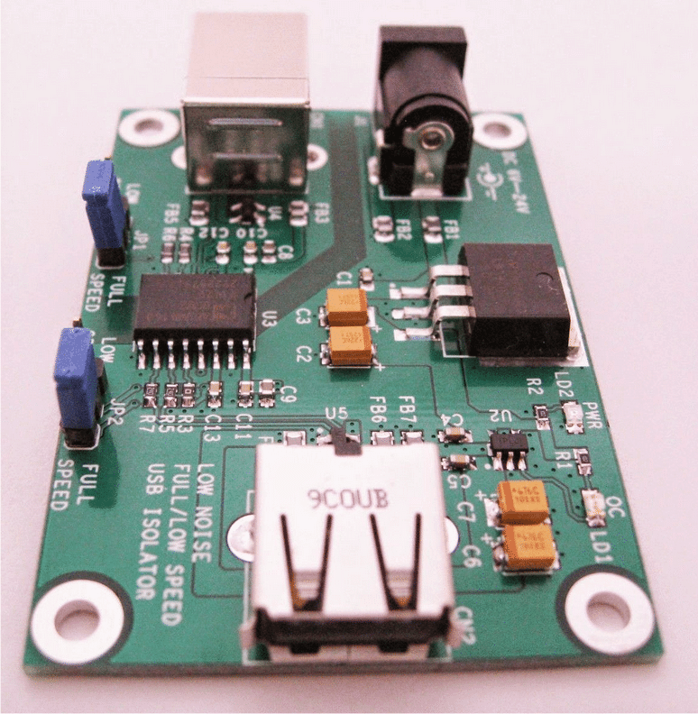
Analyzing the Circuit Idea
Thanks John,
Yes it's definitely an interesting concept to investigate.
However, tt seems to be a difficult circuit and I don't think I would be able to design this one. Let me try, I'll let you know if I happen to crack it.
Best Regards.
Circuit Concept#2
Hi Swagatam,I finally tracked down a schematic of the isolator. Unfortunately the one given to me was small and not clear. Tried to sharpen in Photoshop but it is still poor. It will give you an idea.Details:Low Noise USB Digital Isolator ModuleDescription This module is designed based on ADUM4160, a Full/Low speed 5kV USB isolator.It's a good choice for appilcations that isolation is needed between PC and peripheral device. This module features a low noise power that is very suitble for Hifi devices.In additon, overcurrent protection circuit is included. When short circuit happens in your device, the power supply will be cut off to protect both your device and this module.A red LED will light when overcurrent condition occcurs.Features :
USB 2.0 compatible
Low and full speed data rate: 1.5MBps and 12Mbps, selected by jumper Bidirectional communication On-board LDO regulator for low noise applications Wide power input range: +6V to +24V Downstream port over-current protection ( This function is very useful for protecting your device from damage when short circuit happens)
Circuit Concept#3
Greetings again Swagatam,A helpful guy in China provided this PDF schematic (attached). Now you can find your way around it and explore 🙂John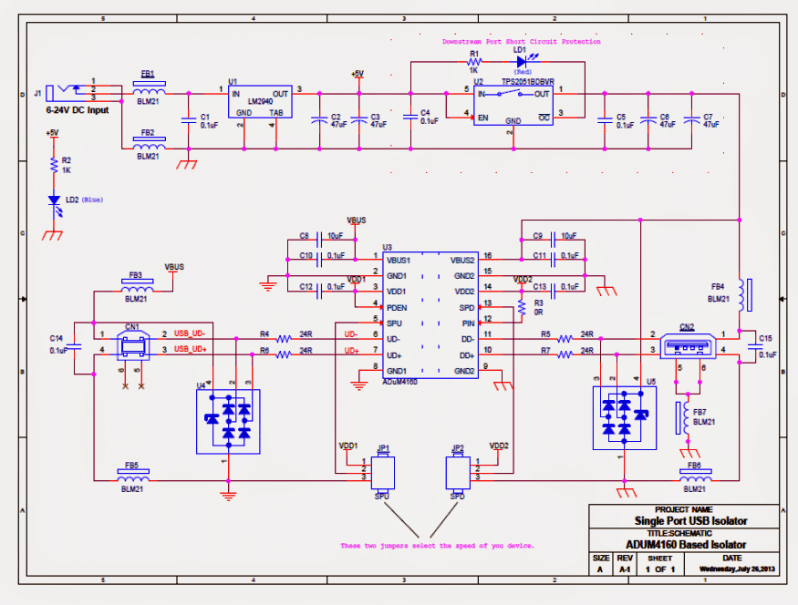
Questions & Answers
In the above circuit diagram of a USB Isolator there are 2 components that I can’t identify, they are U4 and U5, could you possibly tell me what they are, Many thanks
Hello
I don’t know exact PN for U4 and U5. However, they are TVS protections for USB lines.
You can find tons of these components online; for example Texas Instruments TPD4E001RDBVR is ok for the project.
Sorry, I do not have the part value or the specifications for U4, U5.
Hello,
I want to communicate between two USB connectors an I want to add LEDs with USB the data lines D+ and D-, I did a circuit but it does’nt work.
can you propose to me a schematic?
I use a USB 2.0 low speed.
Hello, Sorry, I haven’t yet investigated this concept, so I do not have the required details with me at this moment of time.
Sir i want to charge my andrioad mobile by usening 3.7v battery how i can convert 3.7v to 5v output please help me
mh, you can simply use a 1N4007 diode and a 2 ohm 1watt resistor in series between the 5V positive and the 3.7 batt positive
sir please help me to make a power bank by useing input 3.7v to output 5v
MH, you can try the first circuit from this article:
https://www.homemade-circuits.com/2012/10/1-watt-led-driver-using-joule-thief.html
you'll have to adjust the number of turns to get the right output.
Weldon sir please can you help us with simple diagram of 12v dc to 220ac inverter? Thank you and God bless you for the expensive knowledge you are given to us.
you can try the first diagram shown in the following article:
https://www.homemade-circuits.com/2013/06/modifying-4047-ic-inverter-into-sine.html
Ok sir as I told you before my knowledge on it is very little I want you to help me with full diagram of it,if possible thank you.
thanks basiru, you can look for any IC 4047 inverter circuit and build it, it's the simplest concept I have seen so far….
For those interested regarding the chips used and various PDFs related to the isolator, please google Analog Devices.