In this post I have explained the response of inductors to DC and AC voltages as well as when applied with capacitors which is often used as a complementing part with an inductor.
Properties of Inductor
Inductors are known for their property of storing electrical energy in them in the form of magnetic energy. This takes place when an inductor is applied with an electric current inside a closed circuit.
The inductor responds by storing the electrical energy within it to the particular initial instantaneous polarity of the current, and releases the stored energy back into the circuit as soon as the polarity of the current is reversed or the electrical supply is switched OFF.
This resembles to a capacitor functioning, albeit in the opposite way, since capacitors do not respond to the initial current surge rather stores it gradually.
Therefore inductors and capacitors complement each when used together in an electronic circuit.
Inductor with Capacitor
An inductor will basically behave and produce a short across itself when subjected to a DC, while offer an opposing or restricting response when applied with an AC.
The magnitude of this opposing response or force of an inductor to an AC or alternating current is called the reactance of the inductor.
The above reactance will depend on the magnitude of the frequency and current of the AC, and will be directly proportional to them.
Inductors are generally also named as coils since all inductors mostly are made up of coils or turns of wires.
The above discussed property of an inductor which fundamentally involves opposition of instantaneous current entries across it is termed as the inductance of an inductor.
This property of an inductor has many potential applications in electronic circuits such as for suppressing high frequencies, suppressing surge currents, for bucking or boosting voltages etc.
Due to this suppressing nature of inductors these are also called “chokes” which refers to the “choking” effect or the suppression created by these components for electricity.
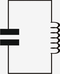
Inductors and Capacitors in Series
As indicated in the above, a capacitor and an inductor which are complementary to each other, could be connected in series or parallel for obtaining some very useful effects.
The effect particularly refers to the resonating feature of these components at a particular frequency which may be specific to that combination.
When connected in series as shown in the figure given below, the combination resonates at a particular frequency depending upon their values which results in the creation of a minimum impedance across the combination.

For so long as the resonant point is not reached, the combination presents a very high impedance across itself.
Impedance refers to the opposing property to AC, similar to resistance which does the same but with DC.
Inductor Capacitor in Parallel
When connected in parallel (see figure below), the response is just the opposite, here the impedance becomes infinite at the resonant point and as long as this point is not reached the circuit offers extremely low impedance to the following current.
Now we can imagine why in tank circuits, the current across such combination becomes the highest and optimal the moment a resonant point is achieved.
Inductors Response for a DC Supply
As discussed in the above sections, when an inductor is subjected to a current having a particular polarity, it tries to oppose it while it's being stored inside the inductor in the form of magnetic energy.
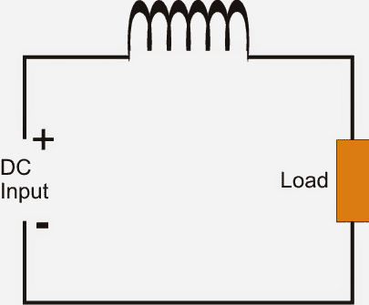
This response is exponential, meaning gradually varying with time , during which the resistance of the inductor is maximum at the onset of the DC application and gradually reduces and moves towards zero resistance with time, eventually reaching zero ohm after some specified time depending upon the magnitude of the inductance (directly proportional).
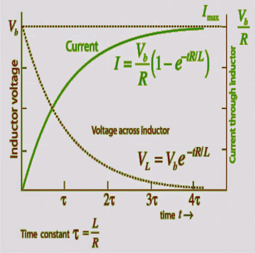
The above response can be visualized through the presented graph below. The green waveform shows the curren (Amp) response through the inductor when a DC applied to it.
It can be clearly seen that the current is zero through the inductor at the onset and gradually increases to the maximum value as it stores the energy magnetically.
The brown line indicates the voltage across the inductor for the same. We can witness it to be maximum at the switch ON instant, which gradually dies down to the lowest value during the course of the inductor energy storage.
Inductor response for AC Voltages
An AC or an alternating current is nothing but a DC changing it's polarity at some given rate also called the frequency.
An inductor will respond to an AC exactly in the manner explained above however since it would be subjected to a constantly changing polarity at the given frequency, the storing and releasing of electrical energy inside the inductor will also correspond to this frequency resulting in an opposition to the current.
This magnitude or the impedance may be assumed to be the average or the RMS value of this continuous give-and-take of electrical energy across the inductor.
Thus in short the response of the inductor to AC would be identical to that of a resistor in a DC circuit.

Questions & Answers
If inductor is connected to led in series ,and then connected in parallel to battery ,what would be the result sir
Greetings Mr. Swagatam Majumdar. please help i have a transformer 220vac to 12vac 12vac 6A each. what do i need to put get 12DC max of 12 amp. sorry don't know where this question will fit in.
i tried using 4 diode 6A05 Bridge type and two capacitors 25/ 10,000 and regulator LM7812
the output of dc volts from
diode 8.5-9v
cap 8
regulator 7-7.5v
sorry really don't know whats went wrong.
email at pandamacproair@gmail.com thanks!
Thanks Panda mac, I am glad it worked for you!
making a windmill from fan is possible, but the fan must be appropriately rated and the wind speed must also be strong enough to generate current at the desired magnitude…
sir swagatam. i followed as you instructed. not using the ground. it works now. all i have to do is to make pwm solar battery charger. many thanks.
if i may ask is there circuit that i can use from a dc fan from a magnetic motion to draw 12v dc? hope my question is clear.
panda mac
Panda Mac, if you are trying to say that your trafo is rated at 12-0-12V, 6 amp, then you may have to use the end wires to get 24V/6amp and feed it to a buck converter for getting 12V 12amps
for example you can use this circuit and adjust to get the required output
https://www.homemade-circuits.com/2015/05/5v-pwm-solar-battery-charger-circuit.html
Sir, I want to learn real electronic circuits, What book do you recommend?.
Tranks for the Blog, it is amazing !!!
Tueresueco, there are plenty of books, so I am not sure which one may be suitable for you, alternatively you can join my personal forum and get full tutorial and help from me
/forums/forum/electronic-circuit-discussions
Sir you are right. It is actually microamps. Thanks a lot
Ok sir! Please one more thing, i exposed an IR-LED to the sun and it produced 20mW(800mV x 20mA), and i exposed an RGB LED to the sun, and it produced 40mW(500mV x 80mA). I want to combine the IR-LED to produce a solar cell for charging my cellphone. It is about 200pieces of the RGB LED can produce 6watt, and 400pieces of the IR-LED can produce 6watt for charging the battery from a cellphone, and its quantity is too much, so i want to reduce the quantity, hence the wattage by connecting the Li-ion cellphone battery directly to the output of the proposed LED-based solar cell. My questions are: What is the maximum voltage and current that is safe for charging the cellphone battery directly? And how can i connect the LEDs(Series-Parallel or Parallel-Series) so as to increase the voltage and current to 4.5v and 0.25amp respectively? And what quantity of the LEDs could be able to produce the power for charging the battery? And what is the normal power for charging the battery directly from the LED-based solar cell without using a cellphone or any charger circuit? Thanks!
Either your meter is faulty or you seeing it wrongly.
No LED will produce 20mA or 80mA when exposed to sun.
It could be uA (microamps) that you are seeing, check it properly.
Please sir, i have tried all my best to produce a joule thief circuit that can initiate charging in a cellphone. But after everything, if i connect the cellphone, the output voltage of the joule thief wil start fluctuating, thereby making the phone to write "charging" and stops again, and writes "charging" again and stops continously. The circuit i used is the one i saw in ur blog titled "1.5v to 12v" hw can i produce a joule thief circuit that can produce 6v 1amp from a 0.4v 1amp source. Please help! I tried the one you titled "1watt LED joule thief" that uses Q=8050. But it refuse to work. What could be wrong?
jideofor, the input wattage should be more than the required output wattage or at least they should be at par.
6 x 1 = 6 watts and 0.4 x 1= 0.4 watts, how can you get 6 watts out of 0.4 watts??
make it 0.4V @ 20amps, then probably it would work.