In the following post I have explained how to drive a relay by using an isolated method, or through an optocoupler device. We will learn three methods, first method is by connecting relay directly with the optocoupler output pins, second method is by using external PNP transistors, and third method is by using external NPN transistors. Any standard optocoupler such PC817, TIL111, or MCT2E can be used in the discussed circuit diagrams.
The question was asked by one of the interested members of this blog, Miss Vineetha.
Before studying the proposed design, let's first understand how an opto coupler works.
How an Opto-Coupler Works
An opto-coupler is a device which encapsules an LED and a photo-transistor inside a hermetically sealed, water proof, light proof package in the form of an 8 pin IC (resembling a 555 IC).
The LED is terminated over a couple of pin outs, while the three terminals of the photo-transistor is terminated over the other three assigned pin outs.
The idea of operating a relay with an optocoupler is simple, it's all about providing an input DC from the source which needs to be isolated to the LED pin outs via a limiting resistor (as we normally do with usual LEDs) and to switch the photo transistor in response to the applied input triggers.
The above action illuminates the internal LED whose light is detected by the photo-transistor causing it to conduct across its relevant pin outs.
The photo-transistor output is normally used for driving the preceding isolated stage, for example a relay driver stage.
Connecting Relay Directly with an Optocoupler
In the following circuit diagram we can see how a relay can be connected directly connected with the collector of the optocoupler's internal transistor.
Remember, although the above connection diagram looks simple and easy, you must ensure that the relay coil resistance is not below 300 ohms, otherwise the optocoupler may heat up and get destroyed.
So if you want to use the above configuration and connect the relay directly with the optocoupler, then you have to first measure the coil resistance of the relay and make sure it is higher than 300 ohm.
This is because, most optocouplers cannot handle more than 50 mA current as the load current, therefore the relay coil must have a relatively high resistance so that it does not pass more than 30 or 40 mA current.
The following concepts show how a relay driver can be configured with an optocoupler using transistors. As shown in the following circuit diagrams, the relay driver may consist a NPN transistor or a PNP transistor.
An external transistor is recommended in a situation where the relay coil resistance is low, below 300 ohms and the relay requires a higher amount of current above 50 mA.
Using PNP Transistor
As can be seen diagram below, a PNP relay driver is connected with the optocoupler. When it's a PNP transistor such as a BC557, the base terminal of the transistor is coupled with the collector terminal of the optocoupler's internal transistor, the emitter is connected with the positive line and the collector pin is configured with the relay.
The freewheeling diode associated with the relay safeguards the transistor from back EMF voltage spikes generated by the relay coil.
The resistor values are not critical, any resistor value between 4k7 and 22K can be used for the two resistors.
Using NPN Transistor
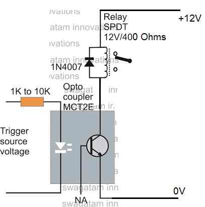
The next diagram below shows how to integrate an NPN relay driver stage with an optocoupler. If an NPN transistor such as a BC547 is used in the relay driver, the switching voltage is received from the emitter of the optocoupler's internal transistor.
Thus, the base of the BC547 NPN transistor can be seen connected with the emitter of the optocoupler transistor, emitter of the BC547 is connected with the ground line, and collector of the BC547 is configured with the relay. The diode has the same function as explained in the previous paragraph.
The resistor value is not critical, any value between 1K and 10K can be used.


Questions & Answers
I want a circuit using opto coupler cutting type it’s output goes to a pnp transistor and then an opto isolator moc3063 is used too control an AC motor of 24 v through an SCR
Hello,
I did not understand what to meant by opto coupler cutting type? Please provide more details.
Hi Mr Swagatam
Thank you for this informative article
Could you perhaps demonstrate how you could achieve reverse operation of the relay?
ie: When the opto led is on, then the relay is off
The problem I have is that the opto transistor will have a 0.7v drop across it when its on which is still enough to switch on a transistor driving a relay when it should be off
Hi Andrew,
You can try the last diagram.
Just connect the base of the relay driver transistor with the collector of the op to transistor.
Make sure to increase the value of the 1K resistor to 10K.
Thank you so much for your quick reply
Would those values be applicable for a 5V circuit and relay with 70 Ohm Coil?
Yes, 10K should work for a 70 Ohm relay also. But for the external transistor please use 2N2222
That did the trick
Thank you so much for your assistance
What you are doing is incredible and greatly appreciated
You are most welcome! Glad it worked. I am always Happy to help!
Hello Sir
how can i connect the three components sir? optocupler, relay and my load (R8).
it would be great if you correct the circuit. please.
Thank you for your help.
i.ibb.co/9Gp87xb/with-optocoupler.png
Hello Abhishek, You have done it perfectly. The method shown in your above link will work. However the opto LED must be reversed according to me. I forgot to show the relay positive connection…please correct that.
Hi sir.
What is the use of BC-547 in this circuit? why don’t we just use the optocoupler to drive the relay?
Hi Beh, most opto couplers are rated at a maximum of 50 mA current while relay coils can be anywhere between 30 mA and 100 mA, therefore an external transistor becomes imperative, which ensures that the opto coupler remains safe from an over current situation regardless of which relay is used.
Hello mrSwagatam,
This my first time of going through your website. I really find it interesting, you are really a leader and doing thing many can’t share.
I really required circuit for automotive voltage stabilizer.
I will be very grateful if my request is granted.
Thank you Olusegun, I appreciate your thoughts! For an automitive voltage stabilizer you can refer to the following article:
https://www.homemade-circuits.com/make-this-voltage-stabilizer-circuit/
Hi,
could I use PC817 as optocoupler for the circuit above?
yes you can use it!
Why do we need to use the IGBT for switching relay. Why can’t we just use the optocoupler to drive the relay?
thanks
Hi Swagtam,
I am making a relay driver for output 220VAC 10A. Input for relay is 5VDC and isolated with optocoupler (MOC3021). However, the whole controlling circuit is using same 5V power (HL PM05) and used common ground for driving the Relay. This will create some noise that upset the sensors attached to the micro-controller. Can you show me some way to separate ground for Micro-controller and the 5V relay without using 02 separated power source?
Thank you very much for your attention.
Ngoc from Vietnam
Hi Ngoc, separating the ground can make the circuit very complex, instead you can try putting stabilizing agents across all the concerned parameters.
You can put a 10uF, 0.1uF, and a 5 V zener diode right across the relay coil.
Do the same across the supply line for the sensors.
The microcontroller would be already having all these on board.
Try this and see if that helps.
hi i want to control a 48 dc motor have tried to source around but failed to get a compatible relay is there any alternative method that i can use
Hi, what kind of control do you want to implement on the motor?
Hello sir,
I have modified the above circuit so please can you just have a look and tell me whether this circuit will work or not?
link for the circuit
https://drive.google.com/file/d/1kSvsSgoAIv2Qw94WIyQcQ-RCZjcgJw7R/view?usp=sharing
Thankyou
Hello Akash,
it looks OK, however the base resistor needs to be increased to at least 10K, and also for better response connect another 10K from the emitter of the opto transistor to the ground line.
(also for better response connect another 10K from the emitter of the opto transistor to the ground line.)
sir,what does this mean?
from the junction of the base resistor and optocoupler pin, connect another 10k to ground, because it is always recommended to keep transistor base to its emitter level through a resistor, so that during an absence of signal, the base does not remain floating
Sir you are GREAT.
once again thank you sir..
It’s My pleasure Akash!
Thankyou sir.
Hello sir,
Is mct2e different from pc817?
Can I use pc817 in above circuit?
Thank you
working of PC817 is similar to MCt2E, but PC817 is more powerful than MCT2E with its specs. yes you can definitely use it…
Hello sir,
I want to operate a relay through optocoupler as shown in the circuit.
Can you suggest a transistor in place of bc547/bc557 to handle current up to 1.5amps,because I want to operate car relay which consumes current up to 1.5 amps.
Thank you
Hello Akash, for 1.5 amps you can TIP31C for BC547, and TIP32C for BC557. However for operating a car relay coil you can easily try 2N2222 for BC547 and 2N2907 for BC557
Thanks a LOT SIR,
I appreciate your help..
you are welcome!
/*
This code was based on BARUTI SPWM code with changes made to remove errors. Use this code as you would use any other BARUTI ,s works.
11/6/2018
*/
const int sPWMArray[] = {500,500,750,500,1250,500,2000,500,1250,500,750,500,500}; // This is the array with the SPWM values change them at will
const int sPWMArrayValues = 13; // You need this since C doesn’t give you the length of an Array
// The pins
const int sPWMpin1 = 10;
const int sPWMpin2 = 9;
// The pin switches
bool sPWMpin1Status = true;
bool sPWMpin2Status = true;
void setup()
{
pinMode(sPWMpin1, OUTPUT);
pinMode(sPWMpin2, OUTPUT);
}
void loop()
{
// Loop for pin 1
for(int i(0); i != sPWMArrayValues; i++)
{
if(sPWMpin1Status)
{
digitalWrite(sPWMpin1, HIGH);
delayMicroseconds(sPWMArray[i]);
sPWMpin1Status = false;
}
else
{
digitalWrite(sPWMpin1, LOW);
delayMicroseconds(sPWMArray[i]);
sPWMpin1Status = true;
}
}
// Loop for pin 2
for(int i(0); i != sPWMArrayValues; i++)
{
if(sPWMpin2Status)
{
digitalWrite(sPWMpin2, HIGH);
delayMicroseconds(sPWMArray[i]);
sPWMpin2Status = false;
}
else
{
digitalWrite(sPWMpin2, LOW);
delayMicroseconds(sPWMArray[i]);
sPWMpin2Status = true;
}
}
}
Thanks for this submission, could you please tell us what improvement you have done in this code? and what error the code given in the article has?? hope you will clarify this for all of us
yes, you can use any optocoupler
Hi sir need your help, i want to make a module relay for arduino, i Using pc817 optocoupler to my module ,but i don't know value of resistor and a transistor? Can you tell to me value of that and what a this schematic can i use to my module? Please help me sir. Thanks you
Jelajah, you can use all the values exactly as indicated in the above article….any one of the schematics can be used for making the module.
the opto LED resistor could be a 4k7…it's not too critical
Can i use an audio signal to trigger the optocoupler. With a high speed diode in series and a cap after that to smooth out the trigger signal
Both optocoupler and cd4017 i'm using for 1 project….
I'm apllying 5v to cd4017….
Pin no 2 I'm connecting to opto coupler Anode,,,cathode is negative….
My question is ,what is the resistor value for opto coupler anode to pin 2 cd4017…shall i use 320, or 470 or 1k….
But cd4017 all o/p giving 3v only …so i need the resistor vakue for connecting the opto coupler…
If any resistor calculation formula for optocoupler,pls tell sir
formula is
(3 – LED Fwd voltage) / LED current
1K should also work since opto LED require very little current but you can use 470 ohm for confirmed results.
Sir I'm using CD4017 ic..input voltage i'm giving 5v but the o/p voltage is 3v only coming so shall i use 470 or 1k…
Kesava, input voltage to 4017 or the optocoupler, please clarify?? for an opto the emitter side will show slightly less voltage than the input, and that does not make any difference since the output transistor will require just 1V to trigger.
Hai sir…..
Small doubt for me..
1.Trigger source voltage means what,is it any ic o/p
2.if i use trigger voltage 5v ,pls tell the value of resistor…1k or 470ohms…
3.pls tell the voltage & current rating of the opto coupler emmiter and collector.
I'm waiting for your reply sir
Hi Kesava, trigger source refers to the external isolated signal which needs to be used for activating the relay
for 5V , a 1K will be enough, although slightly higher will also do.
the C/E rating will depnd on the opto specs which will need to be checked from its datasheet.
Hai sir…..
Small doubt for me..
1.Trigger source voltage means what,is it any ic o/p
2.if i use trigger voltage 5v ,pls tell the value of resistor…1k or 470ohms…
3.pls tell the voltage & current rating of the opto coupler emmiter and collector.
Hi, could you tell us where did you learn that microcontroller output gives 1V? I am interested to see it.
Hi,
How this circuit should be modified in order to have microcontroller trigger the optocoupler? Apparently you can not just connect the left part of the circuit to microcontroller pin as microcontroller provides only 1V on pin high, when 4N25 requires at least 1.3V?