• Skip to main content
  • Skip to primary sidebar

Homemade Circuit Projects

Get free circuit help 24/7

Circuits for Beginners | Basic Circuits | LED Driver | Hobby Circuits | Transistor Circuits

New-Projects | Privacy Policy | About us | Contact | Disclaimer | Copyright | Videos

You are here: Home / Electronic Devices and Circuit Theory / Ohm’s Law/Kirchhoff’s Law using Linear First-Order Differential Equations

Ohm’s Law/Kirchhoff’s Law using Linear First-Order Differential Equations

Last Updated on April 9, 2019 by Swagatam Leave a Comment

ask questions through comments

In this article we try to understand Ohm's Law and Kirchhoff's Law through standard engineering formulas and explanations, and by applying linear first-order differential equation to solve example problem sets.

What's an Electric Circuit

A simplest electric circuit is generally in the form of a series circuit having an energy source or electromotive force input, like from a battery, or a DC generator, and a resistive load which consumes this energy, for example an electric bulb, as shown in the diagram below:


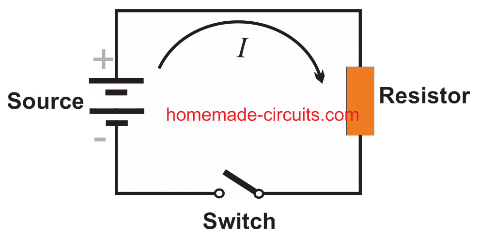
Referring to the diagram, when the switch is closed, current I passes through the resistor, causing a voltage to generate across the resistor. Meaning, when measured, the potential differences at the two end points of the resistor will show different values. This can be confirmed using a voltmeter.


From the above explained situation the standard Ohm's law can be deduced as:

The voltage drop ER across a resistor is proportional to the instantaneous current I, and may be expressed as:

ER = RI  (Equation#1)

In the above expression, R is defined as the constant of proportionality and is called resistance of the resistor.

Here we measure the voltage ER in Volts, the resistance R in Ohms, and the current I in amperes.

This explains Ohm's law in its most basic form within a simple electric circuit.
In more complex circuits, two more essential elements are included in the form of capacitors and inductors.

What's an Inductor

An inductor may be defined as an element that opposes a change in current, creating an inertia like effect in the flow of electricity, just like a mass does in mechanical systems. Experiments have yielded the following for inductors:

The voltage drop EL  across an inductor is proportional to the instantaneous time rate of change of the current I. This may be expressed as:

EL = L dl / dt (Equation#2)

where L becomes the constant of proportionality and is termed as the inductance of the Inductor, and is measured in henrys. Time t is given in seconds.

What's a Capacitor

A capacitor is simply a device that stores electrical energy. Experiments enable us to get the following explanation:

The voltage drop across a capacitor is proportional to the instantaneous electric charge Q on the capacitor, this may be expressed as:

EC = 1/C x Q (Equation#3)

where C is termed as the capacitance, and is measured in farads; the charge Q is measured in Coulombs.

However since  I(C) = dQ / dt, we can write the above equation as:


The value of current I(t) can be solved in a given circuit by solving the equation produced by the application of the following physical law:

Understanding Kirchhoff's Law (KVL)

Gustav Robert Kirchhoff (1824-1887) was a German physicist, his popular laws may be understood as narrated below:

Kirchhoff's Current Law (KCL) states that:

At any point of a circuit the sum of the inflowing currents is equal to the sum of the outflowing current.

Kirchhoff's  Voltage Law (KVL) states that:

The algebraic sum of all the instantaneous voltage drops around any closed loop is zero, or the voltage impressed on a closed loop is equal to the sum of the voltage drops in the rest of the loop.

Example#1: Referring to the RL diagram below, and by combining the Equation#1,2 and the Kirchhoff's voltage we are able to derive the following expression:

Equation:4


Let's Consider this case A with a constant electromotive force:


In the above described equation#4 if E = E0 = constant, then we are able to drive the following equation:

Equation: 5

Here the last term nears zero as t tends to proceed to infinity, such that I(t) tends to the limiting value E0/R. After  an adequately long delay, I will get to a practically constant, without depending on the value of c, which also implies that this will be independent of an initial condition that may be forced by us.

Considering the initial condition to be, I(0) = 0, we get:

Equation: 5*


Case B (Periodic Electromotive Force):


Considering E(t) = Eo sin ωt, then by taking Equation#4 into account the general solution for Case B can be written as:
(∝ = R / L)


Integrating it by parts gives us:


This can be further derived as:
ઠ = arc tan ωL / R

Here the exponential term tends to approach zero as t tends to reach infinity. This implies that once adequately long period of time has passed, the current I(t) attains a practically harmonic oscillations.

get free help for circuit diagrams

You'll also like:

  • 1.  DC Biasing in Transistors – BJTs
  • 2.  Unijunction Transistor (UJT) – Comprehensive Tutorial
  • 3.  Photodiode, Phototransistor – Working and Application Circuits
  • 4.  Comparator Circuits using IC 741, IC 311, IC 339
  • 5.  Diac – Working and Application Circuits
  • 6.  Calculating Transistor as a Switch

About Swagatam

I am an electronic engineer (dipIETE ), hobbyist, inventor, schematic/PCB designer, manufacturer. I am also the founder of the website: https://www.homemade-circuits.com/, where I love sharing my innovative circuit ideas and tutorials.
If you have any circuit related query, you may interact through comments, I'll be most happy to help!

Subscribe for the Latest Posts


Reader Interactions

Have Questions? Please post your comments below for quick replies! Comments should be related to the above artcile Cancel reply

Your email address will not be published. Required fields are marked *

Primary Sidebar


Categories

  • 3-Phase Power (15)
  • 324 IC Circuits (19)
  • 4017 IC Circuits (52)
  • 4060 IC Circuits (25)
  • 555 IC Circuits (98)
  • 741 IC Circuits (19)
  • Amplifiers (59)
  • Arduino Engineering Projects (83)
  • Audio Projects (94)
  • Battery Chargers (83)
  • Car and Motorcycle (94)
  • Datasheets (46)
  • Decorative Lighting (Diwali, Christmas) (32)
  • DIY LED Projects (89)
  • Electronic Components (97)
  • Electronic Devices and Circuit Theory (35)
  • Electronics Tutorial (109)
  • Fish Aquarium (5)
  • Free Energy (34)
  • Fun Projects (12)
  • GSM Projects (9)
  • Health Related (19)
  • Heater Controllers (28)
  • Home Electrical Circuits (100)
  • How to Articles (20)
  • Incubator Related (6)
  • Industrial Electronics (28)
  • Infrared (IR) (40)
  • Inverter Circuits (98)
  • Laser Projects (12)
  • LM317/LM338 (21)
  • LM3915 IC (25)
  • Meters and Testers (64)
  • Mini Projects (156)
  • Motor Controller (66)
  • MPPT (7)
  • Oscillator Circuits (24)
  • PIR (Passive Infrared) (8)
  • Power Electronics (33)
  • Power Supply Circuits (74)
  • Radio Circuits (9)
  • Remote Control (47)
  • Security and Alarm (61)
  • Sensors and Detectors (118)
  • SG3525 IC (5)
  • Simple Circuits (74)
  • SMPS (29)
  • Solar Controllers (60)
  • Timer and Delay Relay (53)
  • TL494 IC (5)
  • Transformerless Power Supply (8)
  • Transmitter Circuits (40)
  • Ultrasonic Projects (14)
  • Water Level Controller (45)


Circuit Calculators

  • AWG to Millimeter Converter
  • Battery Back up Time Calculator
  • Capacitance Reactance Calculator
  • IC 555 Astable Calculator
  • IC 555 Monostable Calculator
  • Inductance Calculator
  • LC Resonance Calculator
  • LM317, LM338, LM396 Calculator
  • Ohm’s Law Calculator
  • Phase Angle Phase Shift Calculator
  • Power Factor (PF) Calculator
  • Reactance Calculator
  • Small Signal Transistor(BJT) and Diode Quick Datasheet
  • Transistor Astable Calculator
  • Transistor base Resistor Calculator
  • Voltage Divider Calculator
  • Wire Current Calculator
  • Zener Diode Calculator


You can also Chat with me here:

Facebook
Twitter
YouTube
Instagram
My Facebook-Page
Quora


© 2022 · Swagatam Innovations

We use cookies on our website to give you the best experience.
Cookie settingsAccept All
Privacy & Cookies Policy

Privacy Overview

This website uses cookies to improve your experience while you navigate through the website. Please visit the Privacy Policy Page for more info.
Necessary
Always Enabled
Necessary cookies are absolutely essential for the website to function properly. This category only includes cookies that ensures basic functionalities and security features of the website. These cookies do not store any personal information.
Non-necessary
Any cookies that may not be particularly necessary for the website to function and is used specifically to collect user personal data via analytics, ads, other embedded contents are termed as non-necessary cookies. It is mandatory to procure user consent prior to running these cookies on your website.
SAVE & ACCEPT