In this post I have explained a simple configuration which can be used as a automatic changeover circuit for switching AC grid mains to generator mains, during power failures or outages.
The explained circuit will effectively switch the connected appliances to the generator mains during power failure however it won't be able to switch start the generator automatically, this will need to be done manually, because most generators involve a difficult mechanical actuation procedure.
How it Works
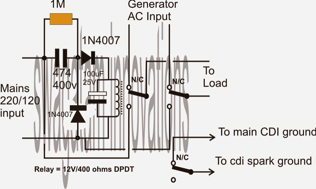
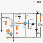
Referring to the given diagram we can see a simple circuit comprising of a TP relay (triple pole relay) as shown below, and a transformerless power supply circuit.

The input of the transformerless power supply circuit is connected to the mains 220V or 120V input.
When mains power is present, the connected relay activates with this power and switches ON the load or the appliances via its N/O contacts.
Conversely when mains power fails, the relay deactivates and connects with the N/C contacts which may be wired up with the generator mains.
Now as soon as the generator is pulled started, the mains finds its way through the connected N/O contacts of the relay to the appliances.
The third set of contacts is used for enabling and disabling of the CDI unit of the generator so that when mains is restored, the generator is automatically halted.
Simple yet effective.....
Circuit Diagram
Analyzing the Part Value Calculations
Voltage Divider Across the Relay (Using 474 Capacitor)
The 474 capacitor (0.47 µF, 400 V) acts as a current limiting element for the relay coil when connected to the AC mains (220 V or 120 V). The current through the capacitor can be calculated using the reactance of the capacitor:
Formula for Capacitive Reactance:
Xc = 1 / (2 * π * f * C)
Where:
- Xc = Capacitive reactance in ohms
- f = Frequency of AC mains (typically 50 Hz or 60 Hz)
- C = Capacitance in farads (0.47 µF = 0.47 * 10⁻⁶ F)
For 50 Hz mains: Xc = 1 / (2 * π * 50 * 0.47 * 10⁻⁶)
Xc ≈ 6,778 ohms
Current Through the Relay:
The current is determined by Ohm’s Law:
I = V / Xc
For 220 V AC mains:
I = 220 / 6,778 ≈ 0.0324 A ≈ 32.4 mA
For 120 V AC mains:
I = 120 / 6,778 ≈ 0.0177 A ≈ 17.7 mA
This current must be sufficient to activate the relay. Check the relays required current (based on its 12 V 400-ohm coil):
Relay Voltage and Power
The relay coil operates on 12 V DC. The current through the coil is:
Irelay = V / R
Where:
- V = Voltage across the relay coil (12 V)
- R = Relay coil resistance (400 ohms)
- Irelay = 12 / 400 = 0.03 A = 30 mA
This means that the capacitor-limited current (calculated above) has to be greater than or equal to the relay's required operating current of 30 mA for 220 V mains.
Diode Rectification
The diodes (1N4007) rectify the AC voltage into pulsating DC for the relay coil. The peak DC voltage after rectification is:
Formula for Peak Voltage:
Vpeak = Vrms × √2
For 220 V AC mains:
Vpeak = 220 * √2 ≈ 311 V
For 120 V AC mains:
Vpeak = 120 * √2 ≈ 170 V
However the relay sees only the voltage dropped across the capacitor and rectified output which limits the current to safe levels.
Filtering Using 100 µF Capacitor
The 100 µF capacitor smooths the rectified pulsating DC into a steady voltage for the relay.
The ripple voltage can be estimated using:
Ripple Voltage Formula:
Vripple = I / (f * C)
Where:
- I = Current through the capacitor (relay current, ≈ 30 mA)
- f = Frequency of rectified signal (100 Hz for full-wave rectification in 50 Hz mains)
- C = Capacitance in farads (100 µF = 100 * 10⁻⁶ F)
Vripple = 0.03 / (100 * 100 * 10⁻⁶)
Vripple ≈ 3 V
3 Phase Grid to Generator Changeover Circuit
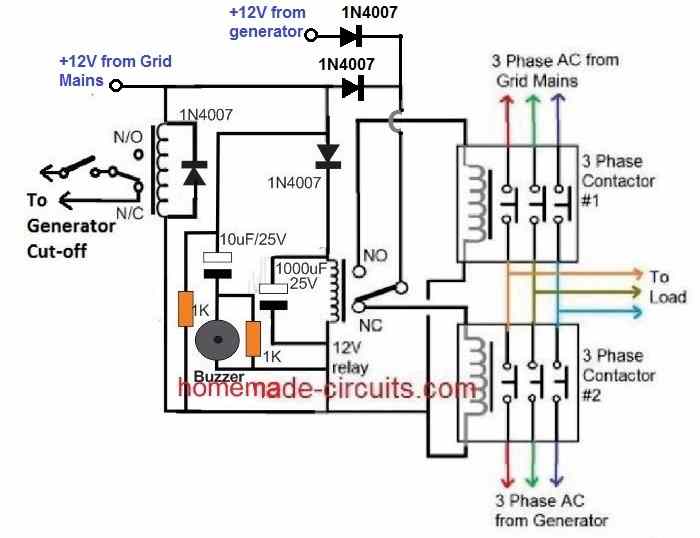
The following diagram shows how a 3 phase grid to generator changeover can be implemented using a couple of 3 phase contactors.
How the Circuit Works
Let's assume mains AC is not available, and generator is switched ON by the left side relay.
In this situation the center relay will be deactivated, and its pole will be connected with its N/C contact, so that the +12V DC from the generator passes through the N/C contact and actuates the bottom/right 3 phase generator contactor.
The top/right grid mains contactor remains switched OFF due to the absence of a +12V DC.
Therefore, the generator AC flows through this bottom/right contactor and operates the connected appliances or load.
Now, suppose the mains grid AC restores.
The left side relay activates and turns OFF the generator. Also, simultaneously the center relay switches ON through the +12V from the grid mains.
The center relay pole now shifts from N/C to N/O, so that the +12V from the mains grid AC passes through the N/O contacts and actuates the top/right contactor. The bottom/right generator contactor is simultaneously switched OFF.
With the top/right contactor switched ON, the grid AC now becomes available to the load.
Again, if the mains AC fails, the left side relay deactivates, switching ON the generator procedures, the center relay connects with its N/C contacts, turning on the generator 3 phase contactors and turning OFF the grid contactors.
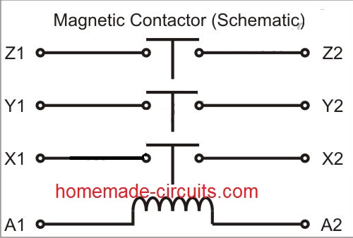
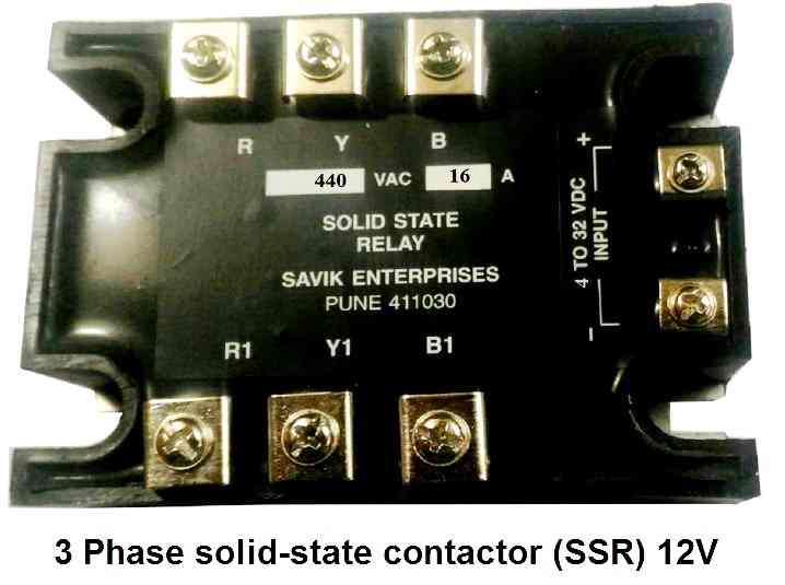
If you are unable to get the above 12V electromechanical relay/contactor, you can go for a 3 phase SSR contactor instead, as shown below.


Questions & Answers
If I need it to connect it to an inverter for mains and when the current goes, the inverter would handle
What will be the modifications ti do?
You will just need a single DPDT relay, the generator AC will get replaced with inverter AC and the lower CDI section will not be required.
Hi, I think that the second circuit of 3 phase should be upgraded course they will be failure to operate 3 phase motor incase one or two phases trips ( that is; only 1 or 2 phases have voltage). I think that the circuit operations will fail if there is voltage in that phase connected with relay coil and absence of voltage in either one or the other two remaining phase course will neither switch to generator nor operate 3 phase machine. I am I right?
Hi, missing phase is a different issue actually, and to prevent it we can include a single phasing preventor with the existing circuit to operate the relay coil
Sir, can one use three SPDT relay connected in parallel, in place of a 3P (three pole) relay? Or would series connection of the three individual coils be a better option?
Alfred, it may be done with a parallel connection, series connection would require three times the coil voltage as the input.
Thanks. How do you connect your CDI GND and cdi gnd with relay.
What is the wattage of 1 megaohm resistance
1/4 watt
Thanks
Hi swagatam can a 373j/400v go in place of the 474/400v in the circuit
thanks
Hi Henry, if your relay is able to trigger comfortably with this cap then it would be fine
please i really need your assistance to build and automatic changeover switch of 90amps 220 volts single phase and it should have the ability to switch off the generator set once there is power from the grid
you can use the circuit that's shown in the above article, it exactly matches your requirement.
thanx for the reply and assistance rendered so far. a have a contactor of LC1D09, it has L1 to L3, T1 to T3 and A1 and A2 two NO n NC that are in the opposite sides of the contactor. i dont know how to use it as a changeover for that your circuit. pls how do i go about it. pls i really need your expectrics. pls come to my rescure
the shown diagram uses it's own recommended relays, it's not meant to be used with a contactor.
I a sorry I won't be able to interpret the details of your contactor.
If you are interested to build the above circuit then you may have to incorporate separate relays as per the power specs of the connected load.
Mr. EKE. I have a design of ATS using two Contactors. I'll be glad to share it with if you wish.
I will be glad if you would share yours with me. I really appreciate your time and support in rendering assistance to me. Thanks alot.
how many pole contactor is the one used above? can i use the above changeover system for heavy amperage as in to be used for an entire flat that has up to 3 deep freezers and two ac units with other appliances? put me through please
yes you can use the above circuit for any desired high current application, you just need to change the relays as per the ampere rating of the load, and instead of a capacitive power supply you may have to use a 12V AC/DC adapter for powering the relay coils
can you tell how it is possible to overcome changeover time.
use a heavy duty relay with low coil resistance, an decrease the value of the input cap to 2.2uF/400V
What is the maximum load that a 30A 250VAC can accommodate if used in the circuit above?? Can it power a house with all the basic appliances?? Thanks
yes this much power is more than enough for powering a house with basic appliances.
The relay will need to be appropriately selected for handling 30A, and also the 474 capacitor which also may need to be upgraded
Hi Sir can I use this above circuit for 40 amp and 63 amp single phase/3phase
yes it can be used but the upper DPDT relay will need to be selected appropriately to handle the large amp.
also for such huge relay, the activation will need to be done through a AC/DC adapter, a capacitive power supply may not be strong enough….
If not then what I have to change in this circuit
great work Swagatam,have learned a lot in the past 6 months.
It's my pleasure Vincent!
if this circuit is used for changeover relay, then how much power losses will take place by the circuit.
sir, please tell me about power losses by this changeover circuit.
power consumption will be as per the rating of the relay coil, could be around 50mA, which will be consumed from the AC mains
Sir, great work on the circuit. But please I need a changeover circuit, this time with three different power sources; generator, AC mains and an inverter supply. So far, what I've come up with is a manual changeover using a bypass, I need one which is automatic. Thanks
Hi NNaka, I already have this design in my website, please search it in the following link
https://www.homemade-circuits.com/search/label/Relay%20Changeovers
hi sir what kind of relay that can be used for this particular change over or i can make use of 3phase contactor to do it
Gbenga, due to low current contactor cannot be used in this circuit, you must use ordinary 400 ohm type relay here….you can probably use the contacts of this relay to operate the contactor and wire the contactor contacts for the overcharge actions
….it's not "overcharge", it should be "changeover" actions…
i would want to request and upgrade to this system, to include a buzzer (using ic 555 timer set at 1minute ), two led indicator (one for main one for generator) The system will do two main function, switch from main to generator when power fails and switch back to main when power is restored . It will sound an alarm that will automatically go off after a period of time , say 1 minutes.
It will have some fail safe features, like , circuit breaker (when main is having low current and one needs to use the generator) and fuse ( for over current protection).
thanks.
looking forward to your quick response..
I already have many such upgraded circuits, you can type “ATS” in the search box and find them, you may also search by typing “generator changeover” in the search box for the same.
sorry to disturb you . none of the ”ATS”, has anything like i requested. being a newbie and yet to be fully capable of design but undergoing training, this idea came to mind and i will want to build it ..
please help.
Only the LED indicators are not included in my other similar articles, which can be simply done by adding an LED parallel with the existing relay coil. LED must include a 1K series resistor
alarm can be made using a small ready made buzzer and wiring it again in parallel with the relay coil. however one of the wires of the buzzer must have a series 100uF capacitor, and a 220K resistor in parallel with this capacitor.
Please help me out I want to design automatic changeover from two main supply Ac mains and generator. With feature that when the main supply is low I can switch to generator. The circuit diagram please. I like your circuit design
If you connect a 150 V zener in series with the relay coil, that will automatically enable the relay to switch OFF at voltages below 160 V
Hi, I have four questions:
1. What are the current ratings of the two contactors?
2. What is the current rating of the relay?
3. From the above diagram, I guess it can be used for kick starter generator? And if so, why is there no stop wires/terminal to switch off generator manually the way there is start wire in the diagram?
4. How can a timer and buzzer be incorporated into the diagram?
I look forward to each of the answers, thank you.
Hi,
The contactor current rating will be as per your generator specifications
The 12V relay can be any small 12V 5 amp relay.
I have only presented a rough idea regarding the changeover stage, for specific applications you may have to add the required adjustments by your own.
The last circuit already has a timer in the form of the base 1M/100uF components for BC547, buzzer can be added in parallel to the relay coil
Ok, thank you. A quick one, the circuit doesn’t not incorporate a stop switch, why?
2. If size of contactors are 100A which, what must be the current rating of the relay? For every application (irrespective of ratings of contactors), must relay be 12V?
The relay coil voltage rating will depend on the supply voltage used for the circuit.
Thank you. Can a stop switch be incorporated into the circuit and how?
For what function do you want the stop switch?
The stop switch is to stop the generator manually. From the diagram, I can see “to generator ignition system” which I have assumed to be the start switch.