In this post I have explained a super capacitor charger circuit for charging super capacitors which converts a 12V car battery voltage to an elevated 16V for charging a bank of super capacitors. The idea was requested by Miariver.
Super Capacitor for Peak Power Compensation
First thanks for keep publishing this blog is very helpful, I have a question and I don't know if this is the right section!!! sorry for any inconvenient.
I am working from my car, running: a laser copier/printer, a die sublimation photo printer, a note book, 2 cellphones, and plus plus.
My inverter is (1500w 12dc-Battery in to 120ac out) a very good one.
after 4 hours of working the battery is getting too low, so the inverter starting to run on protection mode and beeping like crazy. So I decided to run a 6-pack of super capacitor in parallel with the battery to support the (peak moments) the problem is the super capacitor bank need to be charged to 16.2dc volts (6 times 2.7 volts each capacitor)
So do you have any idea how to get 16.2 volts from the 12 volts battery in order to keep the capacitors charged in order to hold the peak load when would be needed.
any idea, advise or circuit, would be highly appreciated.
The Design
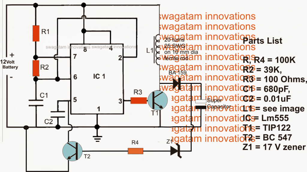
The proposed super capacitor charger circuit for charging super capacitor banks may be witnessed in the above figure.
The entire circuit can be seen wired around the ubiquitous IC 555, configured as a high frequency astable.
High frequency is required in order to drive a compact ferrite coil which becomes responsible for producing the required boosted voltage.
The relatively low current output from the IC is amplified using T1 which switches the connected ferrite inductor at the rate of the fed astable frequency.
The above action induces a calculated boosted voltage across the coil which is appropriately rectified using the attached BA159 fast recovery diode.
The resultant voltage at the cathode of the diode is fed to the associated super capacitors for the intended charging of the devices.
A feedback loop can be seen from the output to the base of T2 which ensures a perfectly stabilized voltage for the super capacitors....in case the voltage tends to rise above the predetermined fixed value, Z1 gets forward biased and switches ON T2 which in turn grounds pin5 of the IC choking the pulse width of the pin3 frequency.
This procedure quickly reduces the output to the safe limits and the cycle keeps switching ensuring that the voltage always stays within the set thresholds.
PWM Control
In the above design, R2 can be replaced with a 100k pot for achieving a PWM output across the load, although it may be not applicable for charging super capacitors, rather for some different relevant application .
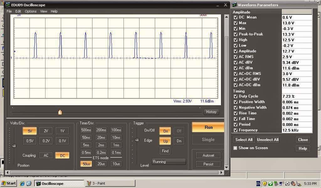
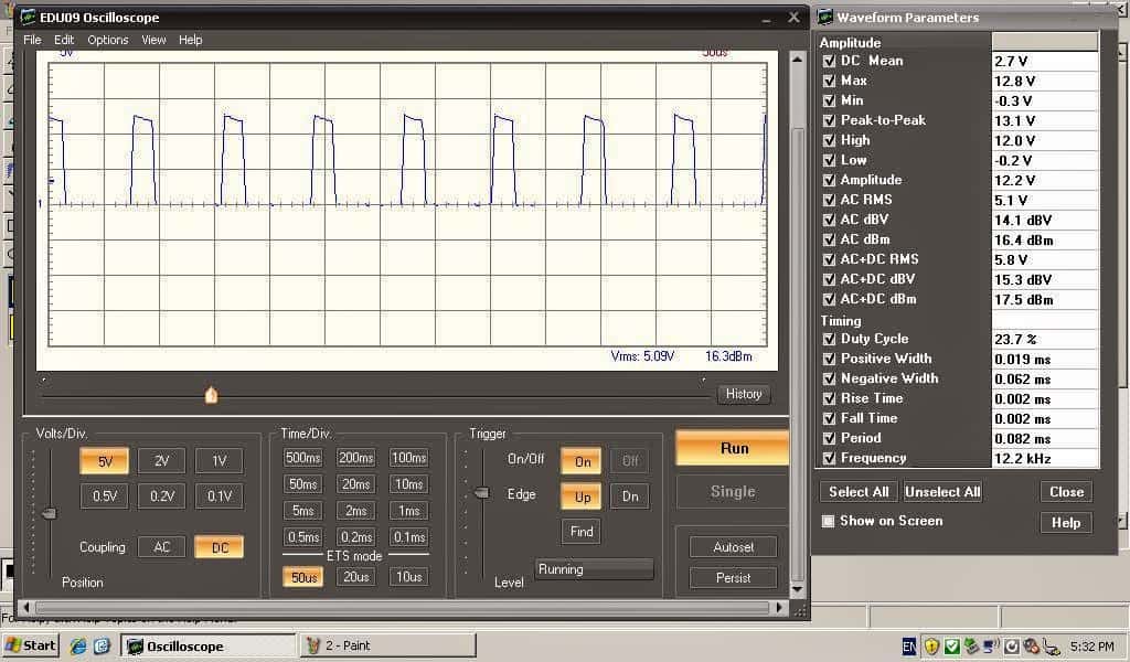
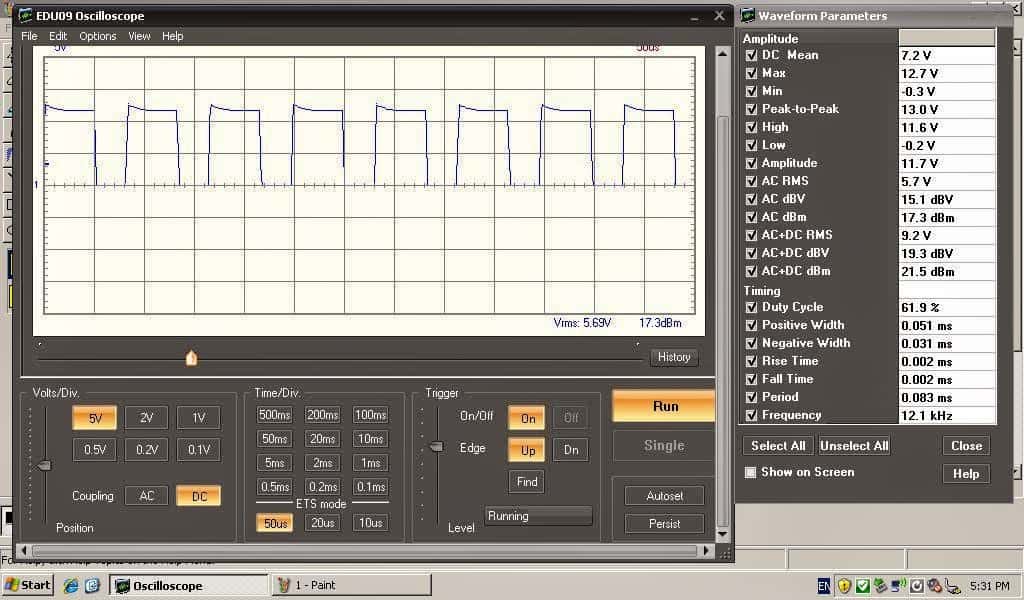
The above super capacitor charger circuit was tested and implemented by Miss Claudia who is an avid follower of this blog and a vehement electronic hobbyist, the verified results for the same may be witnessed with the following images, tested by Miss Claudia:
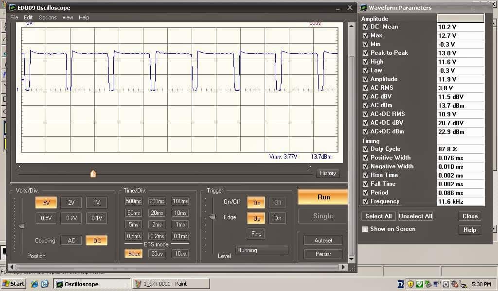
Another Useful Boost Converter Circuit for Charging Super Capacitor Banks from a 12 V Car Battery
Here's a voltage booster circuit which can be used for charging a super capacitor banks from a car lead acid battery.
The boost circuit has an oscillator stage using a BC548 transistor astable.
This transistor astable oscillator generates a high frequency output which drives a MOSFET based boost converter stage.
The circuit also has a feedback circuit stage using the 24 V zener diode which controls the output voltage level by switching the gate of the MOSFET appropriately.
This zener value can be adjusted for getting a customized boosted output voltage for the super capacitors
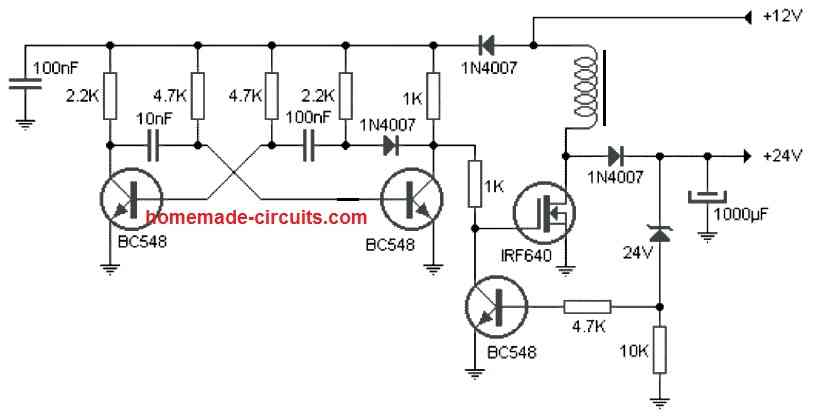
The inductor can be built by winding 30 turns of 1 mm super enameled copper wire over a 1 cm thick ferrite rod or a ferrite ring.


Questions & Answers
so where i s the flux capacitor ? at and if you know any thing about the the e bike battery chargeing circuit .what keeps me from chargeing it up
I made a capacitive charger for desulfation car battery capacitor and bridge and I would like to know if 15.7v is normal for a battery or is it too much
15.7V can be tried on a 12V battery for desulfating it.
Dear Mr. Swagatam,
What is the current output of the circuit? how long it will take a to charge an 83 F capacitor bank from zero to 15V?
kind regards,
Job.
Dear Thykkoottathil Job
sorry I do not have the necessary calculations for the results, it will need to be checked through a practical experimentation
If you have a super cap, they say you can’t charge and discharge at the same time. Can you rotate the charge discharge cycle, so that the capacitor will charge then discharge.
Jim
It can be switched through a relay timer, for example the following circuit can be employed with its connected contacts appropriately wired with the super capacitor, load and the charging source.
Switching Two Alternate Loads ON/OFF with IC 555
Dear brother…
I had wasted my time for two days just looking for BUZ10 at many electronic shop on my town… To make your circuit of driving 2x 100watt led with a couple ic 555. I am finding there are many kind of mosfet here, ex IRF540, and etc, but i can’t to change the part that you are posted without your guide…
But now… I found something interest to read more of your article like this one, more simple, and looklikes easy to build, so i read this article for 3 hours.
My question is…
Which one is better between this circuit and https://www.homemade-circuits.com/underwater-led-boost-converter-with/ this circuit…?
I only need to drive 100w led 33volt from 12volt battery. Built in protection circuit, dimming 100k preset and also safety switch
Many thanks for your time…
sorry, the above IC555 Is a better and easier one since it uses a PWM, so I am changing my suggestion and referring you back to the above design:
you can also simply use a TiP35 BJT for T1, and remove the coil, the diode, the zener diode and the capacitor, and replace the coil with your LED.
and configure the BC547, just as shown in the first diagram from this article:
https://www.homemade-circuits.com/calculating-inductor-value-in-smps/
and yes instead of BC547 use 2N2222
Don’t waste anymore time bro, I would suggest you make the first design from this article:
https://www.homemade-circuits.com/designing-customized-battery-charger_13/
But make sure the input DC does not increase over 38V, that would be bad for the LM338 ICs.
also make sure to replace the 5K pot with a 22K pot
R1 = 1.25/LED current
Thank you very much brother….
I worker hard here as community consultant development, so i only have weekend time for keeping my hobby making useful circuit at home.
I keep insist on trying your circuit as long as i can do. So you don’t think that i will leave from your site :)… I will try step by step and will post it with lucky 🙂
After this project, i will need your advise to built subwoofer controller with volume and frequency control from single supply source.
I have already make it from TL 084, LM5812, LM324, LM741, 062, but no ones better works at single supply.. I feel dizzzy make 2.1 ch satelite huft 🙁
You are welcome bro! I am sure you will not leave, nobody has done so far 😉
However I am not so good with audio circuits, so I am not very sure whether I will be able to guide with regards to a subwoofer design but I may be able to show you some good related links within this site.
Yeah… I feel sure that power supply is heart of electronic, so this site should be the first step for building everything project circuit.:)
By the way i’m not a technician, but i keep learning….
that’s great hilman, keep up the good work!
Hi, I am going to design buck converter and requirement is as follows
Input voltage: 72 V
Output voltage: 54 V
Output current: 15 A
Switching frequency: 10 kHz
I tried to design inductor and capacitor values but did not get good achievement. you may please help to design the same.
Hi, I have posted a few easy to understand posts regarding how to design and calculate buck converters, please use the search box on top to find those, I am sure once you read those posts it will become extremely easy for you to get the best optimization for your application
Back for a moment, i had no time yet to try this solution because i am in the middle of a documentary shoot. But a friend of mine is fighting also with a LED driver. He bought a LED driver that should do between the 28 and 48 Volt….BUT….there is no pot or switch to find on it to adjust the voltage to 33V. Do you know something how this kind of drivers works?
https://drive.google.com/file/d/0B8P7WWCVO6Nwb0JtSktqMlAxZ3M/view?usp=sharing
For me it is a miracle.
you are welcome 🙂
I must thank you very much, his LED's works now with the resistors:-D
may be it's due to the driver's overload feature getting triggered.
remove the transistor buffer circuit which I suggested, and connect the LED directly with the driver through a resistor
resistor value can be calculated as follows:
R = (U – fwd.LED)/I.
R = resistance value required in series
U = driver o/p voltage without LED connected
Fwd.LED = 33V
I = 3amp
He thanks you for your answer, but he says that the LED is blinking, is that correct? It doesn't give continuous light. Can that be solved with a big capacitor?
no problem dear:)
Sorry i was in a hurry …blush
PS: Does the resistor stay's the same?
Thank you mr. Swagatam, i will pass the information throe.
It's an SMPS circuit, like the following one:
https://www.homemade-circuits.com/2014/03/12v-5-amp-transformerless-battery.html
for dropping the volatge to 33V, you can try using a emitter follower circuit using a TIP142 transistor as shown in this example circuit, but make sure to use a 33V zener diode instead of the shown 9V, and 1K 2 watt for the resistor, use a large heatsink on the transistor
https://www.homemade-circuits.com/2012/08/simplest-dc-cell-phone-charger-circuit.html
This link shows the circuit diagram how it is now.
https://drive.google.com/file/d/0B8P7WWCVO6NwdDkzY0RTLS1mNW8/view?usp=sharing
I think there need a diode between each of them, but the one's i have tried don't do the job. I have tried the SB560 and the P600G and both don't stop the influencing from the inductors to each other.
I cannot guarantee whether my "buffer" solution will solve the issue, but you can try it.
first disconnect the center leads of the pots from A1, A2, A3.
take BC547 transistors 3 of them, connect their bases with the center leads of the pots, connect the emitters with A1, A2, A3…and the collectors with the +5V…see if this works
This is how it is connected to the Ardiuno Uno, it are 4k7 pot's
https://drive.google.com/file/d/0B8P7WWCVO6NwRlU0RzZ2R1BObGM/view?usp=sharing
although I am not entirely sure how things are configured, you can try using emitter followers BJTs as buffers with the pots….if you could show me how the pots are wired I'll tell you how to configure the buffers with them…
if ground is a part of the pot connection then it cannot be removed.
I found the problem 🙂
The problem is that i had replaced the circuit for a Arduino Uno, and the pot's are in that system connected with each other by +5V and the gnd. With as result that the pot meters are influencing each other. So it is not the booster part but the pwm part. I just don't know how to separate the pot's from each other. Do you have any suggestions? Removing the gnd connection is that an option?
Hi Miss Claudia! How are you?
If it's cross interference that's causing the issue, it possibly could be controlled using separate inductors in series with the positives of each of the circuits and the battery positive
this inductor could be an air cored type, which will need to be experimented for the turns, probably 50 turns/ 1 inch diameter could do the job
Good morning mr. Swagatam,
I have tried it with 1K ohm and they keep influencing each other.
the connections are OK, but 3 amp for each LED would mean 9 amps from the battery so the battery needs to be at least 100AH rated otherwise the voltage might see a significant drop when all the LEDs are connected together
diode might not be required….try low wattage LEDs or connect a 1K resistor with each LED just to see the response, if it solves the issue then the battery AH rating could be the culprit
So i replace then the 5x 1 ohm resistors for 1 x 1k resistor? is a 0.25W 1k resistor good or must i have 3 or 5w resistor for that?
use a higher watt resistor because 1/4 w could burn…this is to decrease the LED current drastically and check whether the issue is with the current consumption or the frequency interference.
you can also try increasing the filter capacitor value attached with the coil
Ok, i have made the capacitor from 1000uF now 2000uF and the result was the same that they keep influencing each other.
I made 3 boost converters, like in the circuit above here, just the LED is parallel with the capacitor (in your circuit called super capacitor) from 1000uF.
The 3 boost converters i connected parallel together on a battery. So each boost converter got 1 LED from 100W.
Hello mr. Swagatam, how are you doing?
With me all goes great. But i have a question about this circuit. I am using now 3 of these circuits next to each other with one battery, on it self it works but i noticed that when i change the power from one LED, the others are changing to while i don't want that. It looks to me that the coil inductance from all 3 coils are driving power to each other. How can i change this? I have tried to separate the circuits with p600g diodes, but those diodes get fast very hot. Do you have any suggestions how to solve this?
Hi Claudia, welcome back.
how did you connect the three circuits and their coils with the LED? sorry I couldn't figure out the idea??
is there a single LED or three separate LeDs?