In this post I have explained a super capacitor charger circuit for charging super capacitors which converts a 12V car battery voltage to an elevated 16V for charging a bank of super capacitors. The idea was requested by Miariver.
Super Capacitor for Peak Power Compensation
First thanks for keep publishing this blog is very helpful, I have a question and I don't know if this is the right section!!! sorry for any inconvenient.
I am working from my car, running: a laser copier/printer, a die sublimation photo printer, a note book, 2 cellphones, and plus plus.
My inverter is (1500w 12dc-Battery in to 120ac out) a very good one.
after 4 hours of working the battery is getting too low, so the inverter starting to run on protection mode and beeping like crazy. So I decided to run a 6-pack of super capacitor in parallel with the battery to support the (peak moments) the problem is the super capacitor bank need to be charged to 16.2dc volts (6 times 2.7 volts each capacitor)
So do you have any idea how to get 16.2 volts from the 12 volts battery in order to keep the capacitors charged in order to hold the peak load when would be needed.
any idea, advise or circuit, would be highly appreciated.
The Design
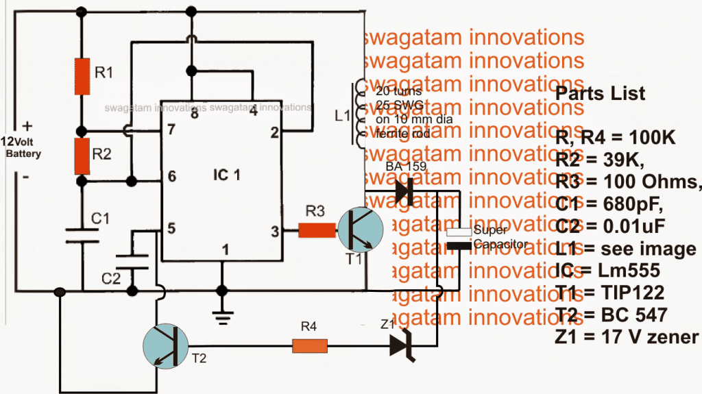
The proposed super capacitor charger circuit for charging super capacitor banks may be witnessed in the above figure.
The entire circuit can be seen wired around the ubiquitous IC 555, configured as a high frequency astable.
High frequency is required in order to drive a compact ferrite coil which becomes responsible for producing the required boosted voltage.
The relatively low current output from the IC is amplified using T1 which switches the connected ferrite inductor at the rate of the fed astable frequency.
The above action induces a calculated boosted voltage across the coil which is appropriately rectified using the attached BA159 fast recovery diode.
The resultant voltage at the cathode of the diode is fed to the associated super capacitors for the intended charging of the devices.
A feedback loop can be seen from the output to the base of T2 which ensures a perfectly stabilized voltage for the super capacitors....in case the voltage tends to rise above the predetermined fixed value, Z1 gets forward biased and switches ON T2 which in turn grounds pin5 of the IC choking the pulse width of the pin3 frequency.
This procedure quickly reduces the output to the safe limits and the cycle keeps switching ensuring that the voltage always stays within the set thresholds.
PWM Control
In the above design, R2 can be replaced with a 100k pot for achieving a PWM output across the load, although it may be not applicable for charging super capacitors, rather for some different relevant application .
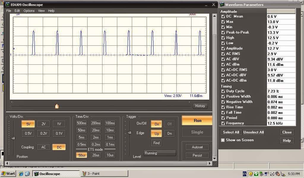
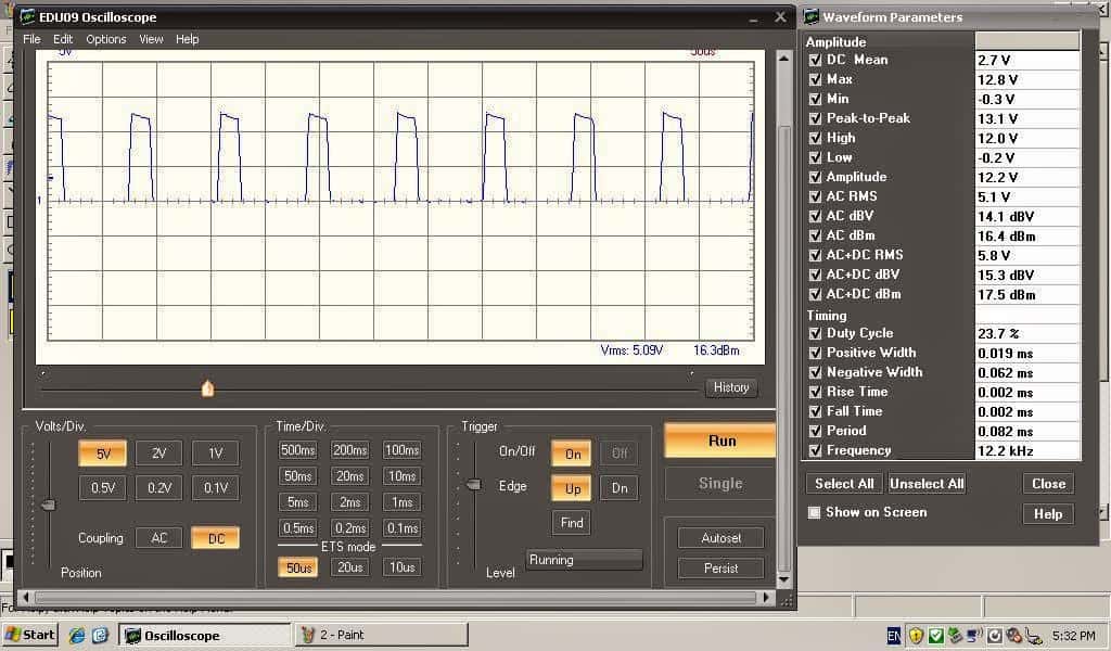
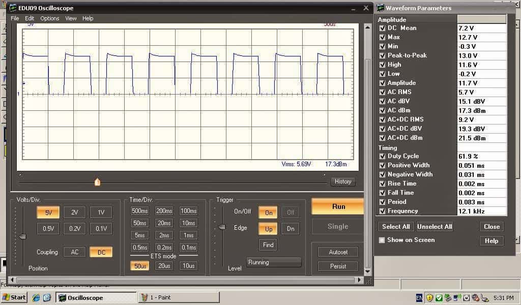
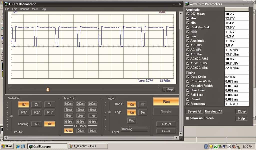
The above super capacitor charger circuit was tested and implemented by Miss Claudia who is an avid follower of this blog and a vehement electronic hobbyist, the verified results for the same may be witnessed with the following images, tested by Miss Claudia:
Another Useful Boost Converter Circuit for Charging Super Capacitor Banks from a 12 V Car Battery
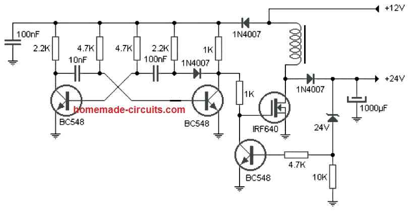
Here's a voltage booster circuit which can be used for charging a super capacitor banks from a car lead acid battery.
The boost circuit has an oscillator stage using a BC548 transistor astable.
This transistor astable oscillator generates a high frequency output which drives a MOSFET based boost converter stage.
The circuit also has a feedback circuit stage using the 24 V zener diode which controls the output voltage level by switching the gate of the MOSFET appropriately.
This zener value can be adjusted for getting a customized boosted output voltage for the super capacitors
The inductor can be built by winding 30 turns of 1 mm super enameled copper wire over a 1 cm thick ferrite rod or a ferrite ring.


Questions & Answers
Hi Mr Swagatam
I
am a continuous blogger of ur site and I visit your site regularly if I need any circuits for my project I refer to your blog for information …Recently I brought a 100w led from ebay along with a 12volt to 32volt 3.5amps adjustable boost driver for the led but unfortunately the driver failed so I thought of building my own circuit.
kindly post a circuit in the blog which would be greatly appreciated
regards
Balaram
Hi Balaram, thank you for visiting my blog, please refer to the following circuit, I think it's exactly what you may be looking for:
https://www.homemade-circuits.com/2014/09/32-v-3-amp-smps-led-driver-circuit.html
Hi Mr Swagatam
I have already purchased this Ac to Dc driver but I need it to run on a 12volt dc source like dc to dc boost converter for 100w led…
regards
Hi Balaram, in that you can try the circuit that's shown in the above article, the coil can be easily tweaked to produce rthe required 32 V for your LED tube light
Hi bla, if it's possible I'll surely try to design the same and post it for you.
Super capacitors are supposed to be connected parallel with your battery ( charge it to same voltage first ) . I got 500F cap with max voltage 16.2 V , I never want to go any higher than 15 V .
thanks Paul for the valuable feed back!
If one where to use a TEG as a power source the input would be a lot less than 12V, more in the range of 1-2V in my intended application. But this circuit would still work, since it's still above the volt needed to trigger the diode, correct?
the IC 555 will need minimum 4.5V to initiate so I am afraid it won't work with voltages lower than 4.5V….a joule thief circuit might work better:
https://www.homemade-circuits.com/2012/10/1-watt-led-driver-using-joule-thief.html
Let's go on here 🙂
Ok, i built it as far as with R1, R2=100k pot, c1=0.2nf, c2= 10 nf and 555.
The measuring results are now:
6.76v = 18.82kHz
6.84v = 20kHz
7.87v = 29.2 kHz
9.66v = 33.7 kHz
on pin 3 from IC1. With a light bulp there is a small variable change visual between pin 3 and ground. The battery measure 12.5V
OK, but you must check the bulb illumination by connecting it across a mosfet drain and positive, that will produce a more effective response…..mosfet gate should connect with pin3 of the IC via a 10 ohm resistor
Done! The values from turning the pot from left to right completely:
12.3v at the bulb, 34.3kHz at pin3
9.82v 28 kHz,
8.72v 20.3 kHz,
8.59v 20 kHz,
8.53v 19 kHz,
Lower then 8.53v it does not come.
But i do see the bulb getting a bit brighter when turning the pot.
OK, so now you can try putting the coil in the shown position and check the voltage response across it.
remember wind at least 30 turns.
ok…i did 40 turns and the mofset burned out completely, the coil became also extremely hot and the wires where i connect all with are melted. I have no measurements because it went very fast. I putted the coil in the place of the lightbulb.
the mosfet will burn if there's no frequency.
I have tested this circuit with a TIP122, and I could light up and 20 numbers of 1 watt LEDs in series…that means the circuit could generate about 20 x 3.3 = 66 volts with a coil wound on a ferrite rod with 40 turns, diameter 1.5cm
Correct. Only the mosfet was damaged and some wires. What happens is that when i turn the pot above the 6.1k ohm, then the frequencie collapse beneath the 30kHz till 4kHz when the potmeter is at 100k. At 0 ohm, the freq is 40kHz. At 10k it is 23.4kHz.
with a 1k pot the freq is stable on 40.1kHz. But i think the pot is drunk because it goes on pin3 from the 555 after the 10ohm resistor from 9.24v to 9.40v to 9.28v when i turn in the same direction totally. With the coil mounted, the voltage is stable on 12.2v no mater what i turn on the pot meter, and with a radiator the mosfet still get hot like ….cooking time. But i saved the mosfet with a radiator this time. The freq with coil is also 40.1kHz now on the gate.
with R1 at 0 ohm your 555 IC will instantly get damaged, and may be you have already damaged it by now…that's why I warned you not to reduce R1 below 1K in the other comment.
I told you to hear the frequency with a headphone in the other comment.
no, R1 is 100k, that one i didn't replaced. I replaced the r2 for a 100k pot and last night i changed it for a 1K to avoid that the freq comes beneath the 30kHz. For the headphone i must make a PAD then because that one works with 0.775v unbalanced and 1v balanced audio. But i googled on the article you said, and i found the principle. Is it possible when the diode and load is missing that the coil can't release its power and it heats up the mosfet?
OK, but R2 will not change the frequency by much..R1 is the resistor which will change the frequency quickly and effectively, and also C1.
you can use a 8 ohm speaker through a 10uF capacitor or any capacitor at pin3 for listening to the frequency
yes without load the back emf can damage the mosfet, but in that case the mosfet will not heat up rather get damaged instantly without any indications….moreover mosfets already have in-bult diode so this possibility may not be so serious with mosfets.
to avoid this danger I had advised you to use a bulb, and check whether or not it's dimming and brightening thoroughly with R2 adjusted from min to max.
if it's heating simply means that the coil is nt proper or there's no frequency at its gate.
At this moment i don't know anymore. I understand the principle but i can't get it working for some reason.
I think i know why it didnt worked. The VGS from a buz11 needs 10 volts to switch and the output from the pin 3 555 was between the 5v and 8v. So that if i understand it right, the frequentie must regulate to switch the mosfet to make the voltage higher or lower throe the coil. But the voltage must be stable at 10v.
if your supply voltage is 12V, the pin3 voltage will also be approx 12V…what you are measuring is the average voltage caused due to the frequency which is breaking the pin3 voltage into pieces…but the peak voltage is still around 12V…the peak voltage is always stable…the average volt might change while the pot is moved due to the change in the PWM (pulse widths)
ok, that is possible….then i don't know. I must first buy new mosfets because they all burned out. i am fighting with resistors to get the right frequencies. I reached today 116kHz and 80kHz to 2.2kHz. I will make a picture from the coil, maybe i do something wrong there. Thank you for being so patient with me, i truly appreciate it.
why don't you first try the circuit with a TIP122 transistor, I did it using this transistor twice and during both the occasions I could make it work at the first shot.
Yea, i will take those tomorrow to with me. It smells like hell, but i better take a bit more from everything :-)))
https://drive.google.com/file/d/0B8P7WWCVO6NwMF9TYUwtcGN6VFU/view?usp=sharing
https://drive.google.com/file/d/0B8P7WWCVO6NwQjFaLUZzS2xfdWM/view?usp=sharing
Here are the pictures from the coil i made and the test board.
He coil looks OK, and it should work, just make sure your IC is oscillating at some high kHz frequency.
The trick is r1, r2 and c1 to get those right. where r1 or r2 must be replaced for a pot.
I tried a lot of combinations, with the results that or the freq is stable and don't move but the voltage on pin 3 goes up and down, or the freq goes from 12kHz to 48kHz but then the voltage is stable on 7volt. But i need it to be stable at 10V with a variation from freq. from 30khz to 60kHz?
the above circuit is very straightforward and not so confusing or complicated as you are experiencing….it should have started working in one shot, I am not sure why you are getting so many issues.
Only R2 should be a pot, R1 can be a fixed resistor, because frequency needs to remain fixed.
use 100k for R1 and any capacitor in the pF range for C1, this will enable an appropriate frequency for your ferrite coil.
frequency needs to be constant, only PWM needs to be changed.
I think the issue may be because you are building it on a breadboard…the circuit needs to be soldered on a PCB for getting accurate results.
I don't know ether why i have such a fight with it, but i am decided i am going to win from this mountain of silicon 😉
Ok, i am going to soldered it like you say and make a picture from it….or a video when it really starts to burn. If you hear nothing anymore, then it has exploded 😀 My family already considers me as a terrorist because i blow up the components.
I appreciate your interest and determination and I am sure you will succeed soon,
yes, solder it on a general purpose pcb and first confirm the frequency and PWM response,
and don't make explosions, otherwise the cops will come knocking on your door, and will be surprised to find a female terr0rist 🙂
Ow that wouldn't wonder anybody when those would nock on my door while i am testing my electro skills :-)) But i am glad you have trust in me.
Ok, done it and the results i could measure with the multimeter is:
6.28kHz = 8.4v
10.61kHz= 9.9v
13.8kHz= 11.4v
14.07kHz= 11.8v
12.10kHz= 12.38v
11.93kHz= 12.55v
On the drain from the mosfet i putted 2 led's in series with a 100ohm to the +.
It dimmed a lil bit with a 100k pot, i had to look on the seeling to see the differences. With a 1k pot nothing was visual changing. Nothing burned out this time.
Now i have seen a video last night about PWM, and how it changes the signal, but i have not a oscilloscope but just a Hz meter on a multimeter, so i cant see it very exactly….but there is movement.
It seems you are gradually learning and improving, that's good,
actually the dimming should be consistent from almost zero to maximum brightness. and you should connect a 1K resistor in series with the LEDs, a 100 ohm is too low.
a 1K pot will not do anything, it should be above 22k to produce any kind of variations in the PWMs.
you may verify the voltage at pin3 which must change from minimum to max when R2 is altered
how much henry must the coil be approx? and what resistance?
Inductance value is not important, even a 10 turn coil will start giving a boost voltage at the output.
just Google "555 flyback boost converter circuit" and check those designs for more info
I am back 🙂
Well, i made a oscilloscope print from Velleman the edu09, so i can see the signal. Don't laugh, but it works good. Now i can see the signal moving that it get wider while the peeks stay max on 12.4v and min on 0.2v. With a variation from between the 1.14KHz and 28 Khz. BUT! when i connect the mosfet and the LED's with the 1k resistor, the dimming is just a little bit at half of the pot meter but further it does not dim. Please don't ask me why the oscilloscope print does work and the PWM not, because the logic is missing to me completely. How are you doing?
that's a great news….however without seeing the images it would be difficult foe me to judge the results.
the range from 12V to 0.2V looks pretty good, it should dim the LEDs to zero.
by the way are you using a transistor as the control device or is it a mosfet?
https://drive.google.com/file/d/0B8P7WWCVO6NwTERHLWJTRWxJajQ/view?usp=sharing
https://drive.google.com/file/d/0B8P7WWCVO6NwQVpSc3MxOXdjMVE/view?usp=sharing
https://drive.google.com/file/d/0B8P7WWCVO6NwOGdUbU9ZWTJHdUE/view?usp=sharing
https://drive.google.com/file/d/0B8P7WWCVO6NwbkViMEJQd2N4TE0/view?usp=sharing
Here they are. I am now using a mosfet for the LED's But it does not dim so much.
I am afraid, the PWMs appear the same for all the images, it means that you are not getting any modulation across the range…and that's the reason the LED is not dimming
see the following image…it should be in this manner:
Ow, i must add that i didn't used T2, R4 and Z1. And instead of TIP 122 i used the BUZ11.
….so now are you getting the required boost voltage across the coil??
I don't know that, i have now just the right PWM signal, i didn't connected anything else then the light bulb.
Can i connect the coil as shown above here, but instead of the 100W LED i use a 1 watt 1k resistor to test the voltage?
welllll…..all went ok, till i connected the coil and then all blew up. It is now a bit smokey so to say. I checked the pwm before i connected the coil, and all looked ok.
I am clueless why it's not working for you…when I built this circuit, I could make it work instantly, in fact I blew a few of my LEDs due to the high voltage from the coil, and because I had no resistor connected in the LED series.
the voltage I could generate was over 70V from a 30 turn coil over a ferrite rod.
I don't know ether. Maybe i must let the idea go to put those LED's on a 12V battery, it would had been handy but i think i better look to make something from 220v to 38V, but then i get the same problem i think because a dimmer works by default with a pwm? I don't know at the moment, i think those high power LED's are a bigger problem to get them work then i thought it would be.
What would happen when i put between the s pin from the mosfet and the – a resistor from 1k, to avoid a shortcut from the coil when the mosfet opens? If i calculated it right then the power throe the mosfet would be something like 0.04 Amp. And over the coil i put a light bulb from 220v to see if something will happen and i can measure the voltage?
I wish I could make it for you and show how simple it is…anyway right now there's nothing much I can do.
There was a copper lane from the + blown off the PCB, the pwm still works, but on 1.2kHz. I checked the resistors and the capacitors but those are ok, the mosfet also still functions. Is the 555 then damaged? As i see it, is that the coil makes a shortcut that gives a high amp? Must there not be a resistor or something between the mosfet and the – ?