In this article we study a simple flyback based converter design which is implemented as an SMPS 12V, 5amp battery charger power supply, without using a iron core transformer.
How it Works
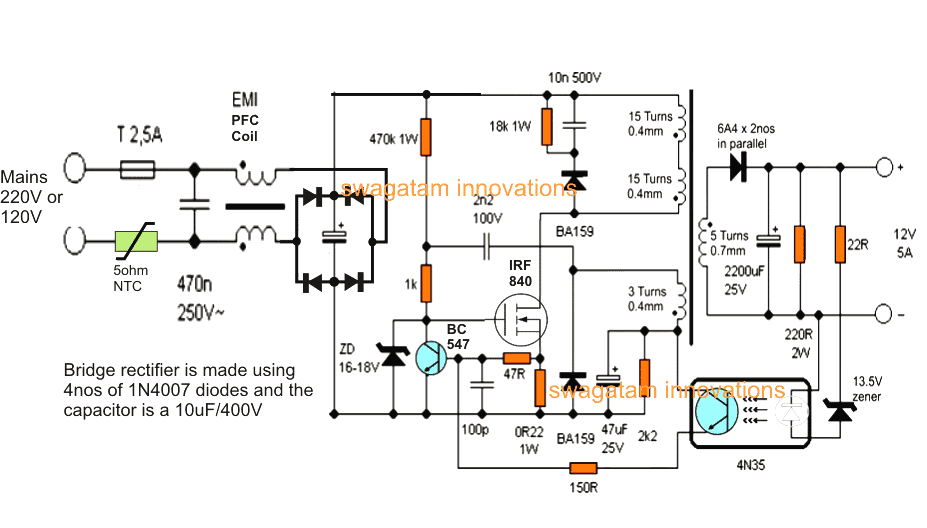
The proposed 12V, 5 amp smps battery charger circuit employs a flyback converter topology which results in the required smps based high current, compact, mains isolated converter design.
Here, the a high power mosfet becomes the main switching component and is used for triggering the ferrite primary winding with the set high frequency mains rectified Dc.
When switched ON, the 470k resistor charges the mosfet gate into conduction and initiates the switching action.
The above action induces a voltage across the auxiliary winding of the transformer which results in a feedback voltage to the mosfet gate via the 2n2/100V capacitor forcing the mosfet to conduct even harder.
As soon as this happens, the primary winding gets connected with the full 310V DC rectified voltage via the mosfet drain/source terminals.
During this process, the voltage across the 0.22 ohm resistor situated at the mosfet source tends to cross the 0.6V level, which instantly triggers the transistor BC546, which shorts the gate of the mosfet to ground, rendering it completely switched OFF.
This also ensures cutting-of the auxillary feedback voltage, restoring the entire primary section to its original switched OFF state.
The cycle now begins afresh and is switched continuously at around 60kHz rate which may be varied by increasing or decreasing the values of the 2n2 feed back capacitor and the 100pF base capacitor of BC546 NPN (it's not recommended though).
During the switched OFF periods of the primary winding, an induced equivalent back emf is transferred to the secondary winding which translates it into the specified stepped down low voltage, high current secondary output.
The above secondary output is appropriately rectified and filtered by the high current diode and a filter capacitor.
A feedback stage across the secondary and the primary stages is implemented via a optocoupler which determines the required fixed, regulated output voltage.
The zener associated with the optocoupler may be tweaked for getting different stabilized outputs for the desired applications.
Here it has been fixed to about 14.4V which becomes the optimal level for charging a 12V lead acid battery.
The current output of this transformerless 12V, 5 amp smps battery charger can also be changed by two methods.
Either by modifying the secondary wire thickness of the transformer or by tweaking the value of the 0.22 ohm resistor positioned across the source/ground terminals of the mosfet.
The input stage typically consists of a bridge rectifier stage, followed by an NTC and filter stage.
The input EMI coil is optional.
Recommended for you: 24watt, 12V, 2 amp SMPS using a single IC Must Read.
Circuit Diagram
How to Wind the ferrite transformer
The ferrite transformer is wound over a 15mm EE ferrite core compatible plastic bobbin.
The one half primary is wound first, using a 0.4mm super enamelled copper wire (15 turns).
Secure the end of this on one of the primary side pins of the bobbin. Cover the winding with a layer of insulation tape.
Next wind the secondary winding (5 turns) using 0.6mm wire over it.
Terminate the ends on the secondary pins of the bobbin.
Apply insulation tape over this winding.
On this wind 3 turns of 0.4mm auxiliary winding, cover it with insulation tape.
Finally continue from the secured end of the first primary winding and wind 15 more turns over the above auxiliary wind to finish of the ferrite transformer coils.
Put a few layers of insulation tape to finalize the winding insulation.
Fix the EE cores and tape it yet again along its periphery.
Make sure the EE core edges are separated with an air gap through a piece of insulation tape or a paper, this will prevent core saturation and stalling of the desired smps induction.
THE CIRCUIT EXPLAINED ABOVE IS NOT ISOLATED FROM MAINS, AND THEREFORE IS EXTREMELY DANGEROUS TO TOUCH WHILE EXPERIMENTING IN POWERED CONDITION, AND ALSO THE DESIGN IS RECOMMENDED SPECIFICALLY FOR USERS HAVING ADVANCED KNOWLEDGE IN THE FIELD, NOT FOR THE NEWBIES..

Questions & Answers
Thank you for this design. Can i power this circuit directly from a battery of 48vdc instead of using AC? I intend using it as power supply in my 48Vdc inverter.
You are welcome. Sorry, No, a 48V will not work as the input source for this circuit.
Instead, you can simply use a buck converter circuit, as described in the following article:
https://www.homemade-circuits.com/buck-converter-calculator/
hello sir, sorry for again. sir
1.
I have a faulty cct of a bty belt. it’s ratting are: I/P =220vAC O/P =14vdc, 10 A. can I use this cct’s o/p transformer in this project?
2. If not then if I use this transformer in this project so what can I change/replace in this cct to make compatible with these o/p ratings (14vdc, 10 A). plz need ur guide.
hey id like to get in tutch with u sir I have some electrical questions I have my basic electricity certificate id like to say im verry self tought and could be great at this with someone to guide me and brainstorm with me i have some amazing ideas and some impressive mad max tonystark projects well if u have the time and enjoy wires and your down with the current like me lol here’s my Gmail mega.cloud94z@gmail.com
Hey Brandon, you can definitely get in touch with me, in fact you can share your thoughts on this commenting platform, so that the other folks here can also benefit from your suggestions and feedbacks…
Hello M.Ahsan,
The transformer must be a ferrite core type and the size and the number of turns must be exactly as per the above given specifications, otherwise it cannot be used.
thank you sir.
can I charge 3 series li-ion btys total (11.1v), wd this cct?
3 series cells will require 12.6V, so you may have to adjust the transformer turns to get this output, and also the max current will need to be limited to 50% of the battery Ah rating..
thank u sir , for 12.6 v what are the transformer specifications?
For 12.6V, you can adjust the 13.5V zener diode until the exact 12.6 or 12.4V is achieved.
Hello sir, Can I buy a readymade ferrite transformer with these specifications from market?
how do I make a toyota camera hybrid battery charger. im working on a number of projects my biggest one is converting my dodge journey into a electric rc car crawler mad max lab lol just need to finish pulling this moter out of it and saying goodbye to the bad emissions
Do you mean Toyota Camry?
Please provide more specifications about the hybrid battery charging system you want…
I will try to solve it for you…
Hello M.Ahsan, If you can get the exact specifications then you can buy it readymade.
Can you explain what the function of the 18k resistor and capacitor coupled with it is, and what the effect is if I change the value of the resistor and capacitor?
The capacitor, resistor and the diode together form a high voltage transient suppressor for protecting the MOSFET.
A slight change in the value will have no impact on the overall working of the circuit.
hi swagatam
thank u so much it was good circuit
to build a switching power suply without i.c
best wishes for u
yasin
Thank you Yasin, glad you found the circuit helpful.
Hello sir,
I would like to have your help to design a Charger circuit for LiFePO4 batter of 12V and 5Ah capacity
need to design from the base circuit
Thank you
Hello Pranav, you can try the LAST circuit from the following article. You must replace the battery with your 12V battery, and the relay with a 12V relay, and make sure that charging input is from a constant current source such as from a LM338 current controller:
https://www.homemade-circuits.com/usb-automatic-li-ion-battery-charger/
Thank you sir
Thanks sir
Because 4N35 has 6 pins and circuit shows 4 points of connection so I am not able to connect.
Please compare the datasheet images of the two opto-couplers to confirm and match their pinouts.
Sir can we use optocupler 817 in place of 4N35.
Yes that will also work…
Inductance or air gap
paper gap is recommended between the E core legs…
Sir kindly suggest paper specification to use right paper, I discussed with transformer manufacturer but he requires inductance or paper gap.
You can insert a layer of insulation tape between the E cores.
Hi Sir for 12v 5a SMPS pls suggest the inductance of primary/ secondary coil.
Hi Mayank, sorry inductance details are not available for this circuit, only the winding details are available.