This little circuit will alert the user regarding a battery reaching its full-charge level (over charge) while it's being charged, by illuminating an LED. The circuit uses just a couple of transistors as the main active components.
Main Feature
The main feature of this design is not only its mini design but also its supply voltage specs which can be as low as 2V, meaning it can be used for all batteries ranging from 2V to probably 60V with minor changes
I have already discussed a similar concept which is designed for exactly the opposite function, that is to indicate the lower discharge threshold of a battery.
Now let's see how the persent circuit is designed to function and how it can be set to perform the required battery warning indication.
We will study two simple designs, the first one will switch ON an LED at the full charge level of the battery while the second one can be used to do just the opposite, that is switch it OFF at the set preset value.
LED Switching ON When Battery becomes Full
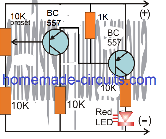
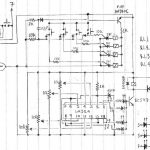
The circuit diagram shown below is intended to illuminate the LED indicator as soon as the connected battery reaches its full charge level.
How to Fix the Presets
To set up the circuit the user has to feed the desired upper charge level to the circuit, and adjust the preset such that the LED just begins to illuminate brightly at that level.
Video Clip:
LED Switching OFF at Full Battery
The following circuit is configured to force or to turn off the LED when the battery reaches its upper charge level.
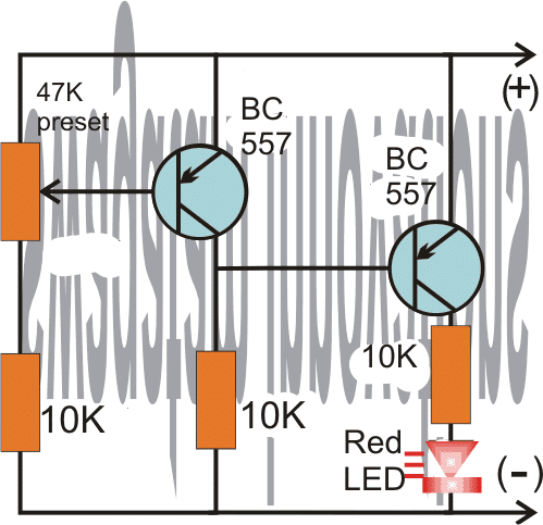
For users who wish to see the LED switch OFF at the upper threshold can use the above shown design, the working may be understood wit the following points:
As per the requirement the LED illumination is supposed to begin diminishing as soon as the battery reaches approximately close to the set full charge threshold.
The setting up procedure of the preset is actually very simple.
The user must feed a supply voltage that may be equal to desired high charge level of the battery, and then gently adjust the preset with a screw driver to force the LED to just shut down at the desired level..
For example suppose the indicator circuit is been installed for monitoring a 12V battery over charge level at 14.3V, then the preset may be tweaked to make sure that the LED just begins shutting down at around 14V.
PCB Design


Questions & Answers
sir swag,
sir you were right,even 0.6v,was not even loss.i measured from the collector of Q2. BIG help!!! ready to set it fixed.
btw sir, i now am currently practicing repairing commercial electronic products such as power amp,tvs ,power inverters,smps, which use power transistors,mosfet,igfet,igbt,
do you have simple circuit to test these with one power supply,combination of pnp,and npn in one circuit. “TO package” thanx
Thanks dennis, glad it is solved.
I have a few tester circuits in this blog, but not sure how effective they may be.
https://www.homemade-circuits.com/?s=meter+tester
thanx sir,
i just took a glimpse and found out that it would help me much testing in-ciruit.i’ll just study which one really works well. keep up sir.
pls,keep helping us,we need you.i learned more every day while studying your circuits.preparing to study basic electronics asap. you really answer queries.thanx
No Problem Dennis, I am always happy to help!
sir swag,
thanks,the circuit works,but i noticed that it consumes almost 1.5v. Nevertheless,i always use it gladly.
btw,pls.help me with this: EMERGENCY LIGHT
1. i made 2s3p li-ion icr18650-22h,connected in parallel,also i modified my cp charger into 9.5v,but still 500mA.is it possible to charge this.what should be the ample current.any advice.
2. leds in series are 3pcs,total of 28 connections in parallel,what should be the resistor value.i want safety for the owner usage.
Hello Dennis, glad to know it worked, however I did not understand what you meant by 1.5V consumption. The consumption is measured in current not in voltage.
The ideal charging current for Li-ion battery is 50% of its mAh rating.
4 Simple Li-Ion Battery Charger Circuits – Using LM317, NE555, LM324
For emergency light circuit, you can refer to the following article:
10 Automatic Emergency Light Circuits
Formula for resistor value is:
R = Supply – LED total FWD V / LED Current
what i meant was, the voltage drops down to 1.5v from the supply as it passes through the circuit,in case, i just need more higher voltage supply to compensate for the drop.i just was curious how much voltage circuit gets.that’s it,thanx anyway.
MORE of your circuit!
As you can see the collector/emitters are protected with resistors, so voltage should not drop at all, not even 0.6V. You will have to check where exactly the current is leaking.
ok sir, i’ll check again.that’s why i just did the circuit in breadboard for assurance before fixing it onto the board.thanx
OK, no problem!
thank you sir,that was i wanted to ask you years ago.answered now,thanx again
Thank you Dennis, I am glad I could help!
sir swag,
good day,how are you .can i use any pnp transistor and i want to add charging led and automatic cut-off when charged.please,help me a design circuit incorporating these with your above design.thanx
Hi Dennis, yes you can any general purpose PNP transistor in the above circuits.
In the first circuit you can disconnect the cathode of the LED and connect it with the base of an NPN transistor such as BC547. The emitter can be connected to the ground, and collector with a relay coil for implementing the cut off action.
thank you .i’ll try and update you if anything goes wrong.sir, what relay should i use if i use it with 2pcs. lithium- ion 3.7v in series.
OK no problem, for the relay you can use a 5V relay.
sir, i have plenty lithium ion 3.7v and lead acid 4v batteries, but were deeply discharged .charging was failed. do you have any design circuit for these.
also,i want to know,how many batteries in parallel can be charged for a single charger 5v,and for this tp4056 charging module for these type of batteries.thanx
Helo Dennis, you can try the last circuit from the following article, for charging your Li-ion batteries. You will have to set the zener the Zx such that the emitter of 2N6284 generates exactly 4.2V, and adjust the ZY zener to a value of 3.3 V for your 3.7V li-lion cells
https://www.homemade-circuits.com/battery-deep-discharge-protection-circuit/
the number of cells in parallel will depend on the current capacity of the charger.
You can connect only one 1000 mAh Li-ion cell with the IC TP4056
The circuit diagrams are great and this is the first real insight I have had into battery charger status indicators. The simple schematic using the two NPN transistors let me see how this can be achieved . I am not an electronic engineer but just an enthusiast and I had a vague idea as to how it might be done and this diagram showed me.
Keep up this great work and I am sure there are many people like me who greatly appreciate this type of stuff.
Thank you.
Glad you found this post interesting, and I hope you are able to succeed with the project, and it answers all your doubts.
Nice level circuit. Unfortunatly not the best approch of battery charging level. What I want to mean that charging top level of batteries is also related to current drown from the batteries.
I saw another circuit with cut off current capability, I will investigate more one that one.
Of course this simple circuit can also have its use 😉
Thx
For current sensing you can refer to the following article:
https://www.homemade-circuits.com/battery-current-indicator-circuit/
Thx exactly the circuits I was refering to. Monitor charged level with LM324 + Auto Cut OFF feature. Perfect to charge batteries ))
Only one detail: what about CV/CC, is IC LM324 handeling that ?
Thx
For CV/CC you either have to use an LM338/LM396 based regulators or build a discrete one using the examples as discussed in the following article:
Voltage Regulator Circuits using Transistor and Zener Diode
for Binoj K: Hello, I have no idea of the time elapsed since the comments, but in response to your question about a circuit that makes the LED blink, I, except for better opinion, would recommend using one of those LEDs that are intermittent for yes, I have used them in different colors.
Hloo sir, it’s fun to see and study your circuits really. May I ask you one thing about the full indication two transistor circuit (first circuit) ,how to make the glowing led(at full charge) to blink also so as to catch easy attention of people that the battery is fully charged. I simply looks how to do it with quite a few ordinary components. Expecting your reply …
Hello Binoj, you can insert the following circuit between the transistor collector and ground of the above circuit, for the blinking effect
https://www.homemade-circuits.com/how-to-make-single-transistor-led/
Thanks for your instant reply. And I tried your suggested blinking circuit with success. Only problem with the circuit is that I want it to work with 9 or 10 volt but at these voltages led stays off. And in one more thing I need your help sir. The led in the full level indicator circuit only light up slowly as battery voltage rises. Is there any possible adjustments or tricks(ie, by using one more transistor or likewise) to make a somewhat sudden turn ON of the led? (with out any relay)
The circuit should work with a 10V supply also, please check the flasher circuit separately with a 10V direct supply. May be the output from the 4017 is not providing enough current to the circuits and might be dropping the volts a lot for the flasher circuit.
The BTJ based circuit will not enable sharp turn ON turn OFf, for that you will need an op amp based design.
Thx for the project. I am looking for a visual indication when charging a BMS 3S, so globaly a 12v battery, can this project be used for this purpose?? What do you think ??
What about Red led on during charging (voltage under 12v or maybe 12.6v) and a Yellow led Off during this time. And when the battery reach 12.6v the opposite happen, so Yellow Led on, and Red Led off, do you thing it is possible without to change a lot the schematic ?? Mayby combine both circuits?
Thx
You can perhaps try the first design from this article for a BMS:
https://www.homemade-circuits.com/3-step-dc-voltage-level-monitor/
This will provide you with a 4 level battery status indications
Hello, I am building a morgan 3 wheeler replica and want an indicator with a battery symbol to light up when the ignition comes on, but will then turn off when a charging voltage is reached, around 13v. Could this be used for that?
Hello, yes this circuit can be used!
Hi I went to know if it is possible for me to replaced 10k preset with 20k preset in the first diagram thanks
Yes you can do it
SIr,
How can it be possible to use buzzer instead of led? i Have a buzzer , it work in 1.5 volt.
Hakan, you can remove the LED and replace it with your buzzer. The series resistor can be changed to 1K
Sir, thanks for the reply.
your advice works in 12v lead acid battery, and buzzer beeping in 14,3 volt, it’s perfect for it. i want to use circuit (LED switching On when the battery becomes full) for 6v lead acid battery and buzzer beeping around 7.3v and up. which component change for my purposes. Your help would be appreciated.
That’s great Hakan, you can use the same circuit for your 6V application also, no need to change anything in the design.
Hi Swag,
I modified the third circuit as per your revised edition and now it works as described. I would suggest the you could change your text to show both options that either indicate that both circuits could be used but one will have the LED on until the set threshold is met and then turn off and the other circuit the LED will be at full brightness when the set threshold is met.
Thanks for your efforts.
I am glad it worked Eddie, and your suggestion looks good, I’ll change the explanation as suggested by you soon…
Dear Sir,
I can’t find your circuit revision regarding the suggestion from Aug. 12, 2018.
I am trying to get red LED turned off at a fully charged battery. Also, I would add a micro fan to it, to enhance LM338 cooling.
Than you for your help.
Nedzad Niksic
Hi Nedzad, the first circuit is the revised one which switches ON when battery reaches full charge voltage. The second circuit does the opposite….it switches OFF at full charge voltage. You can use any one of those as per your specific requirement.
Hello Swagatam
I built two of these circuits with a hope to use them in my Lithium-ion replacement for my Ni-Cad battery packs in a cordless drill. The drill pack is 16.8 volts fully charged so I wanted to set the LED to come on at 16.5 volts. Unfortunately I have found two problems. The first was I used a 50k pre-set as 47k was not available. I now find that the LED is on until I get to the 16.5 volts then it turns off (back to front). The second problem is that the pre-set is nearly fully wound clockwise. Your help would be appreciated.
Hi Eddie,
the preset value is not crucial, you can use any value within the range 4k7 and 47K.
Regarding your issue, that may not be possible unless there’s some problem in your circuit.
As per your setting, let’s assume 16.8V is the cut off threshold, in that case any voltage level below 16V would allow the left side transistor to conduct and switch ON, this will in turn cause the supply voltage to appear at the collector this transistor and subsequently to the base of the right side transistor inhibiting its conduction and LeD illumination….meaning the LED should switch ON only when 16.8V is reached..
Thank you for your quick reply. I meant to so anti-clockwise in my post not clockwise. Both circuits I have built are doing the same thing which I find strange. I have built them both on vero board so they were easy to construct. I have checked them over and over again and can not find a fault. I am using T-092 case BC557 transistors and both are correct in orientation so I am at a loss why a simple circuit like this is not working.
The right way to check the response is to first apply the maximum voltage at which cut off is expected to happen.
then adjust the preset such that it just illuminates the LED at that voltage.
After this the input voltage may be changed to check the response. A lower voltage than the set value should shut down the LEd and vice versa.
Hi Swag,
I have tried your instructions but still get the same effect. I changed the presets to 4.7k which allows setting the trip voltage at the center of the preset. Frustrated I built a third circuit and get the same effect. However, I can make the LED glow at lower voltages and slowly increase to full glow when the trip voltage is reached. If I increase the voltage past the trip point the LED turns off. I can also make the other two circuits I built do the same. I think I prefer that the LED turns off to indicate the lithium batteries are charged. one question, is there a way to make the preset less sensitive to adjustment.
Thanks for your help. Eddie
H Eddie, you were right, the circuit indeed did not work the way it is expected to be, but never mind I have modified it appropriately and now it should be working as intended.
Hi Eddie, I will build and confirm the circuit tomorrow and update the results for you.
By the way if you prefer the LED turns off at the threshold level, in that case your existing situation seems to be fulfilling the requirement?
to decrease the sensitivity of the preset, you can remove the preset series resistor from the shown position and bring it in series with the base of the transistor., this might help to increase the adjustment dial of the preset.
Sir can the LED be replaced with a Relay according to the voltage specifications?
Nkwenti, yes that’s possible, just add a 100uF/25V capacitor across the relay to avoid relay chattering at cut off thresholds.
HI.. please due to curiosity, i wish to ask . what is the voltage at a battery’s terminal when it is on a charging process.
It will be same as the discharged level of the battery at the given instant, and will gradually increase as it gets charged, until finally it reaches the full charge level.
thanks soo much ..
Thanks a million
you are welcome!
Hello swagtam.
Thank uu for recommending the second ckt.
But,what I would like you to shade more light is my batteries were connected in series giving 16v.the issue is that the 2nd ckt has 4.7v zener diode,could it be possible to charge the batteries or my first question was not clear.am doubt pls!come again with another solution
God bless you.
Hello Abubakar,
the zener diode has nothing to do with the battery voltage, you can use any zener between 3 and 9V.
The zener is only for providing a base reference point to the pin#3 so that pin#3 is able to detect the battery thresholds as per the preset adjustment, with reference to pin#2 zener fixed reference voltage.
Hello sir,.
I wonder if you could help me with a circuit to charge 4lithium iron cell of 4v 3/2A connected in series,using 18.1v 100w panel or any other Ac source with automatic quote up or full charge indicator.
Am so greatful for considering me.
Hello Abubakar, you can use the second circuit from the following article
https://www.homemade-circuits.com/2012/01/how-to-make-simple-low-battery-voltage.html
hello sir,
i am a newbie. i want to monitor 3.7v 18650 battery. i have completed this circuit but i can't understand where i have to put the multi-meter to adjust the desired upper threshold. please help me detail with this.
thank you.
Hello Taneem, a meter will not be required for this, you will need a 4.2V source, so get a precise 4.2V supply to the circuit, and then start adjusting the preset until the RED LED just begins glowing.
if you find the the LED glowing initially, in that case adjust the preset until the LED is completely shut off, and then readjust the preset until the LED just begins getting illuminated. that's all is required.
thanks for your help to all of us, I have a fbattery of 12 volts and 120 Ah and I need a circuit to show me when it fully ofcharged , please help me to that.
Thank to you
You are most welcome!
you can try the circuit which is mentioned in the above article, it will faithfully provide you with the required results.
Hi sir,
I need a battery indicator for indicating upto 15v. Also having leds for indicating some different ranges. My email id is;
aamirele@gmail.com
Hi Sheen, you can use the above simple indicator circuit with any voltage level upto 60V…you just have to set up the preset accordingly
Dear Swagatam, very nice little circuit! It could be also used as over voltage protection – just to add a "cut-off" relay to right transistor (in parallel to 10k resistor and red LED). Would be much better than circuit using IC 741 opamp. Why?
1. I do not like opamps if they are not realy necessary;
2. Much simpler to make, more versatile to supply voltages and etc.
Regards, Guitar.mod
Thanks Guitar.mode,
yes definitely it could be used as a battery overcharge cut off simply by adding an additional transistor and relay stage.
I'll try to update the design soon here.
please keep reading…thanks
Sir i created the above circuit and working fine ,but it cut off while volts go up from particular fixed with preset 47k. But i did the little bit changes in circuit i replaced second transistor to bc547 relevant chances to work it. now its ok. thanks for your circuit and test it and if it is true change it and publish.
I appreciate your inputs, thanks very much for updating it…
Hai sir
I currently do the project of Fast Charger For Lithium-ion Mobile Phone Charging that involves raspberry pi. And now I’m still searching the circuit for this project. Can u give me a tips in buid the suitable circuit for this project?
thanks sir. i will wait for it. thanks for help me 🙂
Hi Miss, Presently I do not have a Raspberry pi based design, possibly I'll try to get one soon and post it for you in this website!!
Hi Sachin,
yes that's possible, you can join the (+)(-) of the supply with the relevant terminals of each of the batteries one by one, as each one gets fully charged
that's also possible as long as the units are not attached in any manner except the battery under charger.
Swagatam,
I need to charge all 4 batteries at same time with four individual 12v chargers without disconnecting the series connection (not one-by-one). Possible?
Thanks
Sachin
Hi Swagatam,
I have 4 batteries connected in series which is needed for electric bike.
Is it possible to charge them individually without disconnecting the series connection?
Thanks
Sachin
Hi sir, i want to add an indicator while it's still charging. Any suggestions? 🙂
hi sir,
I am only a 12th pass student…… please tell me what is the meaning of the arrow to the 47k resistance….. thanks sir………Soumen
the 47K is a preset or a trimpot, the arrow head represents the center terminal of the preset
at last it worked,
what will happen if i replace two 10k resistances with 33k, but not replacing the 10k resistance that is connected with led.
OK,
with 33K also It will work with a different preset setting.
LED resistor is only for limiting LED current, it is not related to voltage level detection…..you can use any value from 2.2K to 10K
Sir,
I would like to know how to build a very cheap and simple electric speed controller (ESC) that can work for brushed and brushless DC motor.
Pls sir, I would need a detailed explanation because am new to circuit
Success,
I have explained both the types in this website, please use search box on top right to find them:
just type for
DC motor speed, and
BLDC
can you explain this battery full circuit working on Bread board??
at the preferred high voltage threshold, the left transistor is just forced to stop conducting, which allows the right side transistor to just start conducting via the negative feed from its base 10K resistor.
when the voltage begins dropping below the threshold, the left transistor slowly begins conducting, inhibiting the negative base bias of the right transistor which eventually stops conducting and the LED stops glowing.
i have tried the above circuit, but the led keeps glowing even when the battery powee level goes down.. it keeps on glowing ??
battery low circuit using bc547 is working well but this circuit not…
It should work as mentioned in the article because it's exactly similar to the low batt indicator design except the polarity…
Hi Swagatam, I have been collecting electronic junk and pieces that I want to use in projects and learn. I have plenty of Random transistors with normal numbers and most are "house"? numbered. Sadly I have no 357 or 557 transistors. Can I substitute others? I do have pn2222a, pn2907a, c945 and plenty of unknowns that Google can't find..
Hi Chad,
you can use 2n2907 instead.
Hi, Swagatam! I love your circuits and blog. Thank you! I am trying to make this circuit indicate a full charge of 14.25 volts (for charging a 12 volt NiCad battery). The circuit seems to come on properly at 14.25 volts. When I then lower the voltage, however, the LED stays illuminated. That is strange. It is as though the circuit has "latched" into the "on" state and will not go back to the "off" state. Any help is appreciated!
– Brock
Thanks so much Brock for the motivation, I appreciate it a lot, I will surely start writing an ebook soon and let you know as soon as it's finished.
Thanks so much! I will add a BC547 as suggested and let you know how it works for me. You are the best, Swagatam! Per the other commenter, you should write a book! I'd buy it. In hardback. Full retail price. Better make it an e-book. I am running out of shelf space for hobby electronics books. – Brock
Thanks Brock, yes it will show some level of hysteresis since the design is too basic.
for more sharpness you can perhaps include a BC547 stage at the right side, and connect the LED across its collector arm, that would probably increase the efficiency of the circuit to a much higher level.
remove the existing LED and join the points with a link (don't remove the 10k resistor)
connect the base of the BC547 with the associated BC557 collector…
connect the emitter of the BC547 with the ground line…and finally connect the LED across its collector and the positive line.
make sure to connect a limiting resistor with the LED, any value between 4k7 and 10k will do.
Thank you very much! I appreciate your thoughts!
I have not yet written any book, however i plan to write one, when i do so I'll surely let you know.
What is threshold…?
threshold refers to the voltage level
hi SWAGATAM where exactly is the battery connected to the circuit, i see (+) and (-) which a dc supply input
Hi Davis, the +/- points are the battery points, the supply from the battery powers the circuit and simultaneously helps the circuit to detect its level
Hi sir, I want to use it with 12 v 7.6ah battery but, I want to ask you that during charging the battery connect to this circuit?
mbutho, you can try the following circuit
https://www.homemade-circuits.com/2012/01/how-to-build-gsm-based-cell-phone.html
hi sir my name is mbutho i am also an electronics hobbyist too….so i need your help…..i need a circuit that can switch any single phase appliance using a cellphone…..i hope you will be interested in helping me. i first design the circuit using motors but now i need something more electronical or digi related ……use nanamotsa@gmail.com
Abhishek, yes the above circuit will need to be connected to the battery which needs to be monitored…