In this article I will show how to construct a Faraday flashlight circuit using only a coil/magnet assembly which requires no battery. It’s not free energy, but it converts oscillatory motion to electricity, which can power the flashlight for a couple of minutes. This flashlight will be useful in emergency situations where no access to electricity or batteries.
Construction Details:
The principle used in this flashlight design was first discovered by Michael Faraday, when he proved that when a magnet was moved within a coiled conductor, electricity was generated in the conductor.
The same concept is implemented in this design wherein a magnet is rapidly moved within a copper coil forcing electrons to flow through the wire and generating the required electricity for the LED illumination. In this design we go a step further and enhance it with a joule thief circuit and a super capacitor to produce higher amount of sustained glow on the LED.
The heart of this enhanced Faraday flashlight circuit is the supercapacitor which can charge and discharge at greater rate than traditional rechargeable batteries. The power is generated by oscillatory motion by our hand, which will move magnets to and fro, which induces potential on the coil.
Circuit Diagram
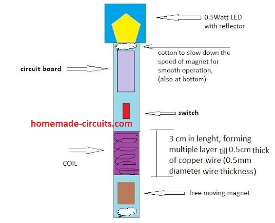
The voltage induced in the coil is fed to supercapacitor, charges and illuminates a 0.5 Watt LED for couple of minutes. A PVC pipe or similar can be used for flashlight’s body, but make sure it’s made of sturdy material and will not wear and tear easily.
A cotton ball or similar soft material should be placed on top and bottom of the flashlight for smooth stopping of the magnet while charging the torch.
The magnets are round neodymium magnets stacked one another which give cylindrical form, around 10 of them are sufficient.
Coil specification:
The coil is vital part of the crank flashlight circuit which charges the supercapacitor. Try to make neat as possible.
• The coil should be enameled copper wire with 0.5mm in diameter.
• The coil should be wounded 3 cm across the tube, and make it 0.5 cm thick with multiple layers.
• Make sure the coil stays tight and protect it with insulation tape or something similar.
The supercapacitor alone is not enough to light a LED, the voltage may drop soon and remaining energy stored in the capacitor stay unused. So we are going to utilize joule thief circuit, which boost up the remaining power in the supercapacitor, which gives extra life to LED.
The Design:
The proposed Faraday flashlight circuit consists of generator coil which is static, and generates power for the supercapacitor. The induced voltage is alternating current due to oscillatory motion; a bridge rectifier is utilized for converting to DC voltage for charging supercapacitor. This circuit summarizes the charging circuit.
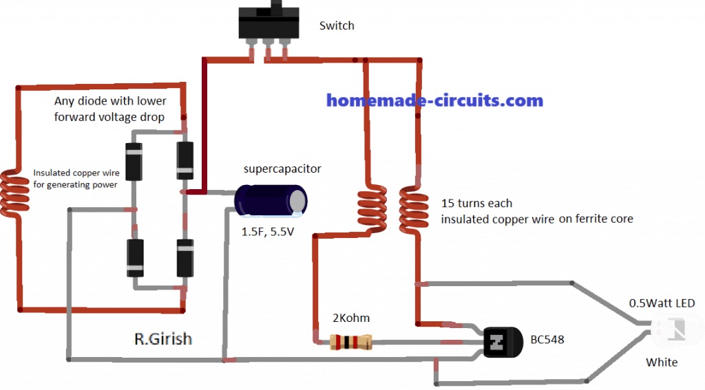
The LED driver circuit is a normal joule thief circuit, which takes low voltage from the supercapacitor and boosts it up for the LED.
For longer LED illumination use couple of standard 0.5mm white LEDs in series instead of one 0.5 Watt led.
Make sure to switch off the flashlight before shaking it (charging).
Do not use supercapacitor with greater than 1.5 Farad as it may take longer charging duration and may be not suitable for this project. Make sure the voltage rating is around 5.5V, using lower value may overcharge the capacitor.
Parts List
- 1 no 1/2 watt 3.3 V LED or you can also try a 20 mA 3.3 V high bright LED for lower consumption and high brightness even with slow shaking.
- 1 no 2.2 k resistor 1/4 watt
- Alternator coil shown on the left side is built by winding many layers super enameled copper wire over a 12 mm diameter 30 mm long plastic former, until the total thickness of the wire layers become 5 mm thick over the former. The wire gauge or thickness can be 0.3 mm.
- The right side joule thief coil could be built by winding two separate turns over a small ferrite ring core. The wire can be super enameled copper wire 0.3 mm thick. Remember while joining the two winding with the transistor circuit, there could be a polarity issue. A wrong polarity will prevent the LED from glowing, if this happen, you can simply try swapping the winding connections on the 2k resistor side, and this will immediately solve the problem.
- 1 no transistor BC548 or BC547
- 4 nos 1N4148 diodes.
- 1 no super capacitor, or you can initially try an ordinary 100uF / 10V capacitor also.
- 1 no Neodymium cylinder magnet, 10mm dia. x 15mm thick
- 1 no ON/OFF switch which is optional
Faraday's Law of Induction
The fundamental principle which works behind a Faraday flashlight is electromagnetic induction, governed by the Faraday's Law:
ε = -N * (dΦ/dt)
Where:
- ε: Induced electromotive force (EMF) or voltage
- N: Number of turns in the coil
- dΦ/dt: Rate of change of magnetic flux
Main Components and Calculations:
Coil:
- Number of Turns (N): More turns induce a higher voltage, but also increase resistance.
- Coil Area (A): A larger coil area increases the magnetic flux, leading to a higher induced voltage.
- Coil Resistance (R): This affects the current flow and power dissipation.
Magnet:
- Magnetic Flux Density (B): A stronger magnet produces a higher magnetic field and this causes an increase in the induced voltage.
Motion:
- Velocity (v): The faster we move the magnet through the coil, the higher the rate of change of magnetic flux and the induced voltage we get.
Capacitor:
- Capacitance (C): It Determines the amount of charge the capacitor can store.
- Charging Time Constant (τ):
τ = RC, This determines how quickly the capacitor charges.
LED:
- Forward Voltage (Vf): The voltage drop across the LED when it's conducting.
- Forward Current (If): The current required to light the LED.
Calculating the Induced Voltage:
Although I don't have the exact calculations and it can be complex, I can simplify it for a basic Faraday flashlight circuit as given below:
ε ≈ N * B * A * v
Where:
ε: Induced Electromotive Force (EMF) or Voltage
This represents the voltage that gets generated across the coil in the Faraday flashlight. It’s what powers the light!
N: Number of Turns in the Coil
The number of turns of wire in the coil matters a lot. The more turns we have, the higher the induced voltage will be.
B: Magnetic Field Strength
This is all about how strong the magnetic field is that’s produced by the magnet. A stronger magnetic field can lead to more voltage being generated.
A: Area of the Coil
The area of the coil is also important. If we have a larger coil area, it can catch more magnetic flux, which means we’ll get a higher induced voltage.
v: Velocity of the Magnet Relative to the Coil
This indicates us how fast the magnet is moving through the coil. The faster we move the magnet, the faster the change in magnetic flux becomes which results in a higher induced voltage.
Why Is It an Approximation?
Faraday's Law can be expressed more precisely as:
ε = -N * (dΦ/dt)
Where:
dΦ/dt: This represents the rate at which magnetic flux is changing.
The easy version of this equation considers that the magnetic field is evenly spread out across the coil area and that the magnet’s speed is constant.
But in real life these conditions might not always hold true perfectly which is why we end up with an approximation instead of an exact answer.
Power Output:
The power output of the flashlight will depend on the capacitors stored energy (charging) and how much power the LED power consumes:
Power = (1/2)CV2 / tWhere:
- C: Capacitance
- V: Voltage across the capacitor
- t: Discharge time
Limitations and Optimizations:
Efficiency:
When it comes to converting mechanical energy into electrical energy, the efficiency is pretty low. This means that not all the mechanical energy gets turned into electrical energy effectively.
Battery Life:
The amount of time the light stays on is limited by the capacitors capacity. Basically if the capacitor does not have a lot of capacity, the light will not last very long.
Power Output:
The brightness of the light really depends on two things, the voltage that gets induced and the specific characteristics of the LED. So if either of these factors changes, it can affect how intense the light is.
To optimize the design you must consider the following:
Using a High-Quality Magnet:
To get the best results we should use a high quality magnet that has a strong magnetic flux density. This is important because it helps us to ensure that our setup works effectively.
Maximizing the Number of Turns in the Coil:
We want to make sure we have as many turns in the coil as possible without increasing the resistance too much. More number of turns can help us to generate more voltage but we need to keep an eye on resistance also, since too much resistance can reduce efficiency.
Using a Capacitor with High Capacitance and Low Leakage Current:
It is a good idea to choose a capacitor that has high capacitance and low leakage current. A capacitor with high capacitance can store more energy and low leakage current means that less energy is wasted over time.
Choosing an LED with High Efficiency and Low Forward Voltage:
When you select an LED you should look for one that has high efficiency and low forward voltage. This way we can get brighter light output without needing too much power which is always a plus point!
Design a Mechanism for Efficient Motion of the Magnet within the Coil:
Finally we need to design a mechanism that allows the magnet to move efficiently within the coil. This movement is crucial for generating electricity effectively so we should ensure it operates smoothly.


Questions & Answers
Hi Swagatam
I have a few questions regarding the joule thief circuit. Firstly, do you have a recommended range for the size of the ferrite core, or better yet, a recommended range for their induction value. Secondly, would it be possible to use axial inductors insted of the ferrite core inductors that you use. I also have a question regarding the magnet’s coil: Could you make one long coil (for example 6 cm instead of 3 cm), with about the same number of coils?
Thank you for your time
Hi Philip,
If you are looking to customize the joule thief transformer, then I think the following article will help you to get all the required calculations:
https://www.homemade-circuits.com/1-watt-led-driver-using-joule-thief/
The magnet coil is quite flexible, and I think you can experiment with it to get the most efficient outcome from it, this will need to be experimented with some trial and error…
what is the bill of material?
You can find it under the “parts list”
Waw it is awesome please I will like you to help me in this.
Dear Swagatam,
Do you have supply list for your Simple Faraday Flashlight project? This looks like something my WEBELOS would enjoy building this year in Scouts, but I don’t know enough about the different components in order to build a supply list myself. Thanks for your help and your willingness to spread your knowledge about this subject.
Thanks James, I have tried to update an appropriate parts list at the end of the post, please check it out.
Hello Swagatam,
Its pleasure to learn from your practical circuits.
I have seen you providing solution to many hobbyists, please help me with one.
I am planning for a circuit which basically prioritizes the inputs.
Consider i have 2 inputs (AC 220V 50Hz mains) from different sources. I plan a circuit which would prioritize P1 over P2 i.e. when P1 is available, the output relay would close the relay to pass P1 at the output, and when P1 is unavailable, P2 would be connected to output.
I tried to design it by simply dropping P1 to 5 to 9 V DC and use this signal to control SPDT relay, but i am worried if that would be practical enough. I am unsure what components i should go with and being mains i am bit worried too.
Request you to design some feasible solution that would provide above function safely and remains feasible not even in preparation cost but runtime power consumption. Also, if it could take care of minor voltage drops at P1 input, i mean it should not keep switching in loop when P1 voltage drops.
Can we add some smoothing circuit at output so the load devices connected at output do not feel the switching transition. I am expecting not much but say 300 to 400 watt load at output.
Thank you for all your help and suggestions.
you are welcome!
Thank you Swagatam.
That helps a lot 🙂
….or perhaps the following design could be also tried (only the triac section)
https://www.homemade-circuits.com/2015/12/invertermains-ac-changeover-circuit.html
thanks Puneet,
the SSR circuit will not work like a SPDT or DPDT relay so anyway it cannot be applied for your requirement. A good quality relay is the only option which could be expected to do the job perfectly, using the diagram which you have preferred.
Hello Swagatam,
That was quite quick! I really appreciate you turned out so quick 🙂
I believe 4.bp.blogspot.com/-p5D8vjC8fd8/U6ukQUa3c3I/AAAAAAAAHXI/uIwZOBmpAXk/s1600/inverter+to+UPS.png has the answer (ignoring battery charger part)
In the side note you have suggested to add 1k resistor across bridge smoothing filter capacitor for quick discharge which would enhance switching response time. I was just wondering if instead of relay we use SSR (https://www.homemade-circuits.com/2011/12/efficient-electronic-relay-ssr-circuit.html), or would it be an overkill.
Thank you
Puneet
Thank you Puneet,
The relay approach is the easiest and the recommended one, so what you have done seems to be correct.
For further info you can refer to the following post:
https://www.homemade-circuits.com/2012/09/automatic-inverter-supply-and-mains.html
please see only the DPDT relay section and its wiring, other details can be ignored.
Using a DPDT will ensure a better isolation across the two mains sources.
you can also refer to the following related post
https://www.homemade-circuits.com/2014/06/how-to-convert-inverter-to-ups.html