• Skip to main content
  • Skip to primary sidebar

Homemade Circuit Projects

Need circuit help? Post them in the comments! I've answered over 50,000!

Blog | Categories | About | Hire Me | Contact | Calculators-online
You are here: Home / Battery Charger Circuits / Battery Cut Off Charger Circuit Using a Single Relay

Battery Cut Off Charger Circuit Using a Single Relay

Last Updated on May 17, 2026 by Swagatam 31 Comments

Amazed to hear this! Yep that’s actually possible, you would need only one relay and a handful of diodes to make a simplest one relay automatic battery charger circuit.

Table of Contents
  • How it Works

How it Works

The idea struck me while trying to design the easiest possible battery charger circuit for one my clients.

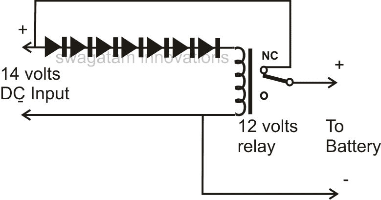
The concept is simple; just raise the operating or triggering voltage of the relay up to the optimal battery charging threshold voltage by dropping the required amount of supply voltage to the relay coil, with the help of series diodes.The idea may be understood from the following points:

Take an ordinary relay, measure its triggering voltage by carefully applying a variable voltage across its coil.Now suppose the triggering voltage of the particular relay was about 9 volts, and also assume you want to raise its voltage to 14 volts, which may be your 12 volt battery’s charging threshold voltage.

We know that a 1N4007 diode drops about 0.6 volts across it, so if we add sufficient number of diodes in series with the relay coil would hopefully pull its tripping or triggering voltage to about 14 volts.

That means, 14 – 9 = 5, we’ll require 5/0.5 = 10 diodes in series to achieve this rise in the triggering voltage of the relay.That’s pretty simple and interesting isn’t it?The rest may be done with the help of the shown diagram…..your simplest single relay automatic battery charger is ready.
You'll also like:

  • 12V to 19V compressed12 V to 19 V Boost Converter Circuit
  • Battery Backup Time Indicator Circuit
  • simplestli ionbatterychargercircuit4 Simple Li-Ion Battery Charger Circuits – Using LM317, NE555, LM324
  • multi cell li ion volatge controllerSeries 2S, 5S Li-Ion Cell Charger using BQ7718

Filed Under: Battery Charger Circuits Tagged With: Battery, Charger, Relay, Single

About Swagatam

I am an electronics engineer and doing practical hands-on work from more than 15 years now. Building real circuits, testing them and also making PCB layouts by myself. I really love doing all these things like inventing something new, designing electronics and also helping other people like hobby guys who want to make their own cool circuits at home.

And that is the main reason why I started this website homemade-circuits.com, to share different types of circuit ideas..

If you are having any kind of doubt or question related to circuits then just write down your question in the comment box below, I am like always checking, so I guarantee I will reply you for sure!


Previous Post: « Introduction to Schmitt Trigger
Next Post: SMD LED based Emergency Lamp Circuit »

Reader Interactions

Questions & Answers

Total Posts: 31
Newest Oldest
Stefan
March 1, 2025 • 1 year ago #168716

there would be a problem with the triggering of the relay which will not be firm from the beginning and a transition period will create an imperfect contact with vibrations of the contacts

Reply
SwagatamAdmin
March 1, 2025 • 1 year ago #168717

Why it will not be a firm triggering? Vibration issue can be solved with a 220uF capacitor connected across the relay coil…

Reply
mike digregorio
August 18, 2024 • 2 years ago #158247

i have an electric bike with a 48v battery the bike model is vivi ebike f26f…. i believe if in the brief research i did and hoping i wAS RIGHT IN my take from the information that was presented to me and was understood as it was intended to if my assumption is right then the battery(48v battery) can be charged with lowest voltage output of roughly 39.4v or lets just say 39v (obviously will take a longer time period to fully charge with this voltage output) and the actual charger provided to consumer who purchases this model ebike is 54.6v
2a output . so i need a 48v 13maH – 54.6v 2a if i am stating all accurately awesome if not could you help by one simplifying the correct electrical spesifications for this model for me and my main and most important inquiry for this is i have had my charger lost or stolen or w.e i have looked around in stores for a charger that will do the job and i have to if i want it as soon as say the following day it needs to be like amazon well amazon messed it up sent the wronf onw then sent it back from the locker . for the electrical v output i need from a power brick charger. i am now more determined to turn this 24v output power brick into the right voltage and ampage of my needs. it can be easily done?

Reply
SwagatamAdmin
August 18, 2024 • 2 years ago #158261

If your battery is a Li-Ion battery (and it should be a Li-ion battery for a bike), then the actual full charge level of your battery has to be 50.4 Volts, and the lowest discharged level is supposed to be 36 Volts.

So your charge must be regulated to produce around 50 Volts with a maximum constant current of around 50% of the battery Ah rating.
Please let me know if you have any further questions…

Reply
Noor
April 16, 2023 • 3 years ago #141820

Hi, Thank you for shearing the knowledge and well explanation. I have made a 2 battery charging circuit. I am having a problem of shattering relays when it cutting off the battery charging voltage. Please any suggestion much appreciated.
Thank You.

Reply
SwagatamAdmin
April 16, 2023 • 3 years ago #141827

To prevent chattering of the relay you can try adding a 470uF capacitor parallel with the relay coil.

Reply
Noor
April 16, 2023 • 3 years ago #141828

Thank you for the quick response. Could you please let me know type of capacitor, electrolyte or any kind. Thank you sir.

Reply
SwagatamAdmin
April 16, 2023 • 3 years ago #141829

A 470uF capacitor will be always an electrolytic, so it should be an electrolytic.

Reply
Ajward
November 18, 2022 • 4 years ago #135145

Dear sir,
Can we use resistor or a pot instead of diodes.

Reply
SwagatamAdmin
November 18, 2022 • 4 years ago #135160

No, pot or resistive divider will not work instead of diodes.

Reply
M.I.Ajward
November 20, 2022 • 4 years ago #135407

Dear sir,
I would like to know whether it is Ok if I charge the 12v 36 ah car battery continuously with a 14v 1amp charger without auto cutoff circuit. I appreciate your reply.

Reply
SwagatamAdmin
November 20, 2022 • 4 years ago #135427

Hello MI,
yes it is perfectly OK. but with 1 amp your 36 Ah battery cannot charge properly, or might taken a very long time to get fully charged.

Reply
shrikant ranade
April 30, 2021 • 5 years ago #88896

I want some simple 5 volt relay projects with led
i also purchase pcb boards of this project

Reply
SwagatamAdmin
May 1, 2021 • 5 years ago #88904

You can use all the 12V relay projects from this website and convert them to 5V relay projects by replacing the 12V relay with a 5 V relay and replacing the 12V supply with 5 V supply

Reply
kavin
November 19, 2020 • 6 years ago #84639

How to design a relay to fix between laptop charger plug and brick and to control the relay using mobile phone

Reply
marwerno
June 30, 2020 • 6 years ago #80044

Hi,
exactly what I was looking for (I was always thinking of a way with Z-Diodes).
But I believe there is a small error?
You write:
“14 – 9 = 5, we’ll require 5/0.5 = 10 diodes”
0.5 represents the Voltage drop of the diode, but in the N4001 example it would be 0.6 right?
That would change the calculation to 8 Diodes?
Thanks,
Markus

Reply
SwagatamAdmin
July 1, 2020 • 6 years ago #80058

Thank you for your feedback and suggestions!

Reply
Grtech
June 16, 2019 • 7 years ago #67697

Please share a automatic charging cut off circuit for 12v 35Ah battery.
can I use 12v 2A tranfo.?

Reply
SwagatamAdmin
June 16, 2019 • 7 years ago #67707

you can these circuits:
https://www.homemade-circuits.com/high-current-10-to-20-amp-automatic/
https://www.homemade-circuits.com/opamp-low-high-battery-charger/

Reply
untung suharto
February 10, 2017 • 9 years ago #48832

Hi, friend this is can workout well charge SLA battery?

Reply
SwagatamAdmin
February 11, 2017 • 9 years ago #48850

yes it will work….

Reply
Farhan Ali
December 31, 2015 • 11 years ago #37208

yes relay starts to switch on and off. i have made this circuit.this is due to disconnection. it order to overcome this connect 14v dc to battery positive terminal not through the NC of relay.

Reply
Unknown
November 26, 2015 • 11 years ago #36246

Sir, thank you for sharing your idea on this simple circuit.
What components will be required if I need this same simple circuit to charge 48 volts battery made from 4 x 12. The battery AH is not important.

anticipating your quick response

Thank you once more

Reply
SwagatamAdmin
November 26, 2015 • 11 years ago #36257

sorry this circuit is not recommended for a 48V battery because too many diodes will be required for the 48v operation …….moreover the design is not too accurate.

Reply
SwagatamAdmin
February 23, 2014 • 12 years ago #20083

Actually, I was wrong in acknowledging the zener idea, it won't work.

It has to be done exactly as suggested in the diagram in the above article. 1N4007 or 1N4148 in series with the relay coil is the only correct way of doing it.

Reply
Ahmed Elmasry
February 22, 2014 • 12 years ago #20072

hi i take your idea and make this circuit …

im75.gulfup.com/3SLo5.png

Reply
SwagatamAdmin
February 23, 2014 • 12 years ago #20082

Actually, I was wrong in acknowledging the zener idea, it won't work

It has to be done exactly as suggested in the diagram in the above article. 1N4007 or 1N4148 in series with the relay coil is the only correct way of doing it.

Reply
Ahmed Elmasry
February 22, 2014 • 12 years ago #20071

i take your idea and made this circuit :im75.gulfup.com/3SLo5.png

Reply
rohit choudhary
December 22, 2013 • 13 years ago #18453

Please share a automatic cut off circuit so that , I can charge a mobile battery , with mobile charger.

Reply
SwagatamAdmin
December 23, 2013 • 13 years ago #18469

you can try the second circuit published in this article:

https://www.homemade-circuits.com/2012/07/make-6v-4ah-automatic-battery-charger.html

Reply
SwagatamAdmin
November 12, 2013 • 13 years ago #17175

12v input will not charge a 12V battery

Reply

Need Help? Please Leave a Comment! We value your input—Kindly keep it relevant to the above topic! Cancel reply

Your email address will not be published. Required fields are marked *

Primary Sidebar


My Youtube Channel

Circuit Simulator

circuit simulator image


Subscribe to get New Circuits in your Email


Categories

  • Arduino Projects (95)
  • Audio and Amplifier Projects (134)
  • Automation Projects (18)
  • Automobile Electronics (103)
  • Battery Charger Circuits (88)
  • Datasheets and Components (109)
  • Electronics Theory (149)
  • Energy from Magnets and Earth (40)
  • Games and Sports Projects (11)
  • Grid and 3-Phase (20)
  • Health related Projects (27)
  • Home Electrical Circuits (13)
  • Indicator Circuits (16)
  • Inverter Circuits (99)
  • Lamps and Lights (162)
  • Meters and Testers (72)
  • Mini Projects (28)
  • Motor Controller (68)
  • Oscillator Circuits (28)
  • Pets and Pests (15)
  • Power Supply Circuits (91)
  • Remote Control Circuits (50)
  • Security and Alarm (65)
  • Sensors and Detectors (107)
  • SMPS and Converters (45)
  • Solar Controller Circuits (60)
  • Temperature Controllers (43)
  • Timer and Delay Relay (50)
  • Voltage Control and Protection (44)
  • Water Controller (37)
  • Wireless Circuits (31)


Other Links

  • Privacy Policy
  • Cookie Policy
  • Disclaimer
  • Copyright
  • Videos
  • Sitemap

People also Search

555 Circuits | 741 Circuits | LM324 Circuits | LM338 Circuits | 4017 Circuits | Ultrasonic Projects | SMPS Projects | Christmas Projects | MOSFETs | Radio Circuits | Laser Circuits | PIR Projects |


Recent Comments

  • Swagatam on True MPPT Solar Controller Circuit using IC 555
  • Swagatam on Electronic Circuit Projects, Tutorials, and Practical Engineering Solutions
  • Swagatam on Simple 20 watt Amplifier Circuits
  • Miracle on RC Helicopter Remote Control Circuit
  • Dale on Simple 20 watt Amplifier Circuits

Social Profiles

  • Twitter
  • YouTube
  • Instagram
  • Pinterest
  • My Facebook-Page
  • Stack Exchange
  • Linkedin

© 2026 · Swagatam Innovations