The proposed circuit was requested by one of the avid readers of my blog. It is a low battery warning indicator circuit using op amp IC 741 and can be used for monitoring a particular low battery voltage threshold.
Circuit Operation
The circuit may be understood with the following points:
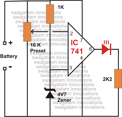
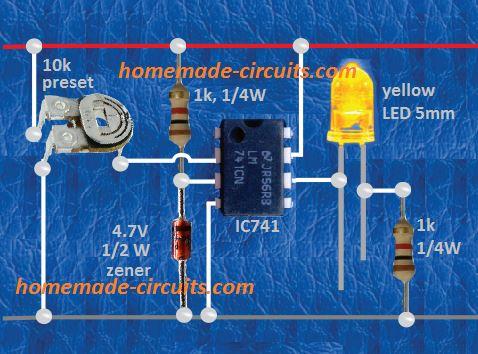
The entire configuration is wired around the IC 741 and it becomes the heart of the circuit.
Basically it is configured as a comparator with one of its inputs clamped to a fixed reference level while the other input used as the sensing terminal.
Here as can be seen in the diagram, the non inverting input is provided with a fixed reference voltage through a resistor zener network.
This input is fixed to about 5 volts.
The other inverting input pin #2 is wired via a preset to sense the input supply voltage from the source.
The preset is adjusted such that the voltage level at this input becomes lower than the fixed reference voltage at the other pin of the IC as soon as the source voltage becomes lower than the desired threshold level.
When this happens the output of the IC immediately becomes high, illuminating the connected LED.
The illuminated LED immediately provides the indication of a low voltage situation so that the required actions may be initiated.
Optionally, the output may be replaced by a piezo buzzer instead of the LED for getting an audible response of the above situation, eliminating the headache of monitoring the LED condition every now and then.
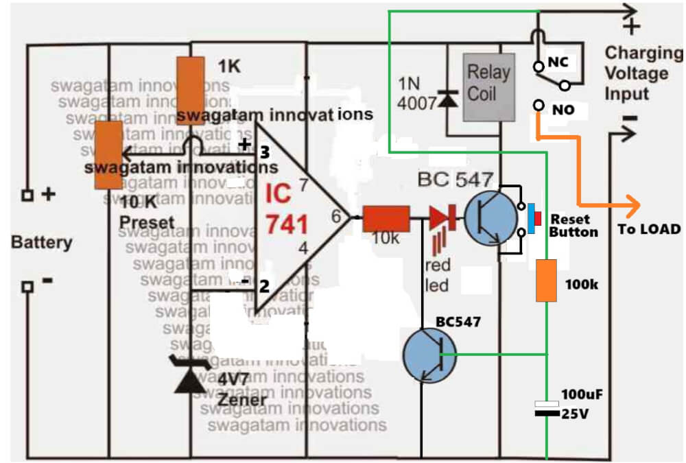
The above circuit can be modified by adding a relay stage for a latching facility, so that the relay latches and stops oscillations at the set low battery thresholds.
How to Setup this Low Battery Indicator Circuit
The above low battery indicator circuit can be even further improved in the following manner for controlling both lower and the upper charging thresholds:
Initially keep the 100K preset link disconnected.
Apply a 14.4V source from the "Battery" side and adjust the 10K preset such that the upper relay just activates, confirm the triggering by subsequently moving the preset to-and-fro.
Glue it once fixed.
The LED will respond by switching ON to the fixing of this preset.
Now reconnect the 100K preset feedback link, and reduce the input supply to about 11.2V. Make sure it has a high resistance initially.
Next, slowly adjust the 100K preset such that the relay just deactivates (at the 11.2V).
Confirm by flipping the preset as above. Ignore the lower relay as it will switch ON as soon as the input supply is switched ON, so its operation is obvious.
That's it, the low battery warning circuit is all set now and will accurately respond to the above settings or any different setting that may be preferred and implemented by the particular user.
IC 741 Low Battery Indicator Circuit with Relay Cut-off
The following circuit shows how the above low battery indicator can be enhanced with relays for achieving an automatic low charge and full charge cut for the connected battery, and also a cut off for the load during a low battery situation.
The upper relay becomes responsible for cutting off the battery during over charge and low discharge level, while the lower relay cuts of the load as soon as the battery reaches the unsafe low discharge zone and as soon as the upper relay reverts to charging mode




Questions & Answers
Hello sir. My question is, my relay flickers when the battery voltage reaches 10.5v which is the cut of point. I used lm358 OpAmp. Is it okay
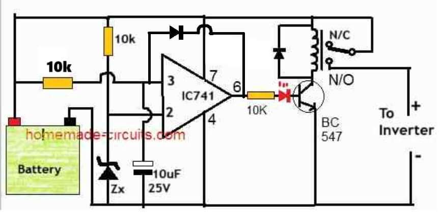
Hillary, please try adding a diode between pin#3 and pin#6 of the opamp, as shown in the following diagram, and let me know if solves the problem or not.
What zener diode should I use if my battery is a 3.7v 300 – 3500mah Li-ion battery (includes Li-po batteries too)
You can use a 3V zener diode, or, 3 or 4 1N4148 diodes in series, connected between pin#3 and ground….cathode towards ground.
Hello swagatam sir, I need to design a power supply failure indicator using IC741 op Amp,can you help me to design this mini project.I tried a lot but still there is no out come . Please accept my plea
Hello Sujal,
Can you provide more information about the project. Bceause power supply failure can be detected simply by putting an LED. If the LED shuts off that would mean there’s no power supply. How do you want to use the IC 741 and where exactly?
Sir, basically by using ic741 ,led,resistors capacitors and diode I need to make a small power supply failure indicator. The working should be in such a way that that the LED should glow when there is fluctuations in power supply or when the power supply is cut.
OK Sujal, let me see, I will try to figure it out and let you know soon….
Thank you sir
Sujal, there’s one question, if there’s no power supply, how will the op amp and the LED indicator work?
Sir even I am unaware of the answer for your question, but I found out an article for this problem with circuit diagram. can I know your mail so that I can send it to you.thank you
You can send the image to contact@homemade-circuits.com
Hi Sujal,
I saw your diagram in the email. The circuit uses a battery, so if you use a battery in your circuit then it is possible to build it. The battery can be a 9V battery.
Sir I have sent you another mail please do check it.
Sujal, I have uploaded the diagram in the below link. There are a few things I cannot understand myself. Where is the source of the external power supply? Which is the reset switch SW1, or SW2. I guess it is SW2. And, is your circuit working?
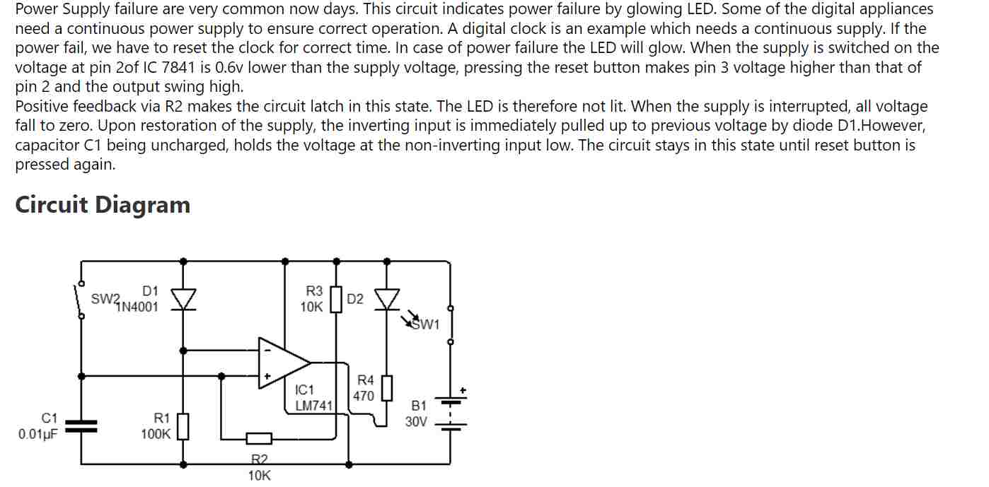
Yes sir I assumed reset switch as SW2 and I gave 9v battery as the power source, when I give power to the ckt the light blinks and when I take off the power supply it blinks. I am unable to understand what’s happening inside the circuit.i will refer to the circuit given by you
I can provide you the op amp circuit which will illuminate an LED when the external power supply fails or becomes low. But my circuit will require a battery also, a 9V battery….
yes sir please provide me with the circuit you are discussing about,I have a 9v battery .It would be a great help to my project
Sujal, You can try the following circuit:
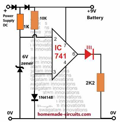
All diodes are 1N4148….
Sir thanks alot. Just one last doubt,what value of power supply should I provide to the ckt. also can you provide me with the working of this circuit if possible
Hi Sujal, the power supply DC should not be above 15V otherwise the IC 741 will burn.
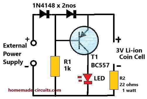
It is a comparator circuit, with its non-inverting input (+) clamped to a 1N4148 to create a 0.6V reference. The inverting input (-) is connected between two diodes to ensure that it is able to detect only the external power supply DC and not the battery DC.
As long as this external power supply on pin#2 of the IC is higher than the pin#3 potential of 0.6V the output of the op amp remains 0V and the LED remains shut off.
In an event when the external power DC on pin#2 goes lower than the pin#3 0.6V, the op amp output swings to +9V battery level and thus illuminates the LED.
Thankyou soo much sir. ❤
You are welcome Sujal!
Sujal, please add a 1N4148 diode from the battery +9V side also, otherwise the external power supply +DC will try to enter the battery and damage it.
Ok sir , sir one more doubt, can I use 1N4001 diode instead of 1N4148 as they are equivalent….
Yes, you can use 1N4001 diode for all the diodes shown in the diagram.
sir i made the circuit and it is working perfectly. Once again i thank you whole heartedly for your help and will stay connected with you for your help in my future projects <3.
Thank you Sujal, Glad it worked for you. Please feel free to comment if you have any further doubts
I am after a simple cct to operate a relay to showw high dc voltage of 40v and must run between 24v to 45v.
Can you help please.
Please elaborate, I could not understand the exact functionality you require.
I have a battery charge that needs a simple cct that turns off the charger when the voltage gets to 41.0v. It need s operate a relay that can switch 240v ac 2a max
You can try the following concept:
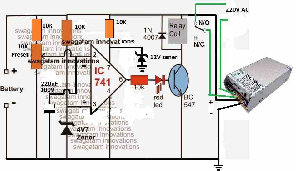
Hello sir, I have tried the circuit today but the second relay that is connected to the load is not bringing output
Sir, my requirement is how to make low voltage indicator and cut off circuit for inverter
OK, then you must try the second circuit from the above article. Just make sure to swap the pin#2 and pin#3 with each other, and replace the “charging input” with your inverter +/- supply inputs.
Also please remove 100K preset feedback link, we can modify it afterwards when the circuit is confirmed by you.
Hello Micheal,
Please tell me your exact requirement, I will try to suggest the right circuit for you.
how to prevent the charging circuit from very high current drawn from 12V car lead acid battery when they are as low as below 8V. My own circuit have often burnt by bridge rectifier and transformer.
You can take the help of a current limiter circuit as explained in the following article:
https://www.homemade-circuits.com/universal-high-watt-led-current-limiter/
Hi Swagatam,
We exchanged some comments on one of your other pages (IC 741 Car Alternator Voltage Current Regulator Charger Circuit) and you suggested I take a look at the first circuit in this article. If you remember I was looking for a circuit to add an ignition warning light to an old motorcycle.
I picked up a few 741’s from a local webshop and have been playing around with the circuit on a breadboard. With the LED in the circuit it works as described. I have been testing with an old lab power supply to alter the voltage supplied to the circuit. Trouble was I need to modify it to get a 12v signal from the output (pin #6). The “dashboard” of the bike has fittings for the small BA9 lamps and I have installed LED replacements, but of course they are modified internally to work on 12v.
I read up here and other sites on the working of the 741 and it seems like to get 12v out I needed to put a 12v reference voltage in (pin #3). So I looked into the working of the resistor zener network and changed the 4V7 zener for a 12V example. The 1K resistor seemed to work OK and I get a reading of 11.9V at pin #3 which lights the 12V LED OK. Now this needs to go out when I turn up the voltage to around 13- 13.5V, but adjusting the 10K pot feeding the inverted input (pin #2) never raises the wiper voltage to be above the reference when the lamp should go out. I tried a couple of other pot values without success and the only change that seems to work is removing the 10K pot and feeding the changing input voltage (as would be put out by the bike’s generator) direct to pin #2.
So my question is – does this seem like a suitable modification to create a stable project? Or would you modify it differently? Looking forward to your thoughts, thanks.
Hi Martyn,
The 12V zener at pin#3 of the IC is not necessary. You can use any zener diode below 9 V and still setup the circuit to cut off at the desired threshold. The 10K preset adjusts the pin#3 threshold in accordance with the zener reference, so any zener below 9 V should work.
However if you are able to get a zener diode whose value is exactly equivalent to your desired cut-off threshold, then you can replace the 4.7V zener with this zener diode. In that case you can also eliminate the preset and connect the pin#2 of the IC directly with the source DC.
As far as the working of the preset/pot is concerned, it will definitely allow the voltage at its wiper arm to be adjusted right from zero to the maximum supply voltage level. If it is not doing this then either your preset is faulty or you may have connected it wrongly.
OK – so I looked at again and you could be right about the 10k pot. It was from a cheapo assortment from China. I found a better enclosed version which seems more reliable and that performed better with the 12v LED lamp. Couldn’t find the time to etch a board for it so just soldered it all to a small project board and it seems to work as hoped with the old lab supply. Just need to get the bike running and adjust it to function correctly with the alternator supply. Many thanks.
Sounds good! Hope it works correctly in your bike. Wish you all the best!
Sir, if I need to use the first lm741 circuit for batteries of 4v or 6v, do I need to change the zener value or any other component values? If possible, how can I set up the cutoff using the preset for a 4v and 6v bat?
Binoj,
for 4 to 6V battery you can replace the 4.7V zener diode with a 3V zener diode or you can use 3nos of 1N4148 diodes in series. Cathodes will go towards the ground line
Sir I think the the n/o contact of the relay so that when the battery reaches the full voltage level and the op-amp becomes high at its output and triggers the transistor to switch on the relay (turns to the n/c contact) and with this the battery is unable to charge further. Sir this is just a suggestion
Melvis, which circuit are you referring to?
Hi swagatam.
1)Can i use the first circuit (the one without a relay, with just the LED) with a 12v battery source?
2) if yes, can i replace the LED with a buzzer because i want to build this circuit so that the buzzer would sound at exactly 12.0vdc
3) In other to achieve the above requests, do i need to change any of the components (e.g the zener diode)
Thanks.
Hi Chris,
1) yes you can use the first circuit with a 12V supply
2) Yes you can replace the LED/resistor with a piezo buzzer unit.
3) You can do the above without changing anything in the design
Thanks for the quick response Swags.
If i build this indicator circuit for a 12.0vdc battery (for my inverter) and the piezo buzzer is activated(as in a low battery condition) how about if i connect the battery to a charger(my solar panel) and the battery voltage rises above 12.0v would the buzzer be deactivated automatically?
Hi Chris, yes as soon as the battery voltage increases above set low level threshold, the buzzer will stop buzzing, and vice versa.
Hello sir the last circuit u referred me to in this article I have built but the 100k preset is not responding to any feedback by deactivating the relay. The 10k preset do.???? what is it?
Hello Morris, the 100K preset decides at what lower voltage threshold the battery must be reverted to charging. It has a systematic setting up procedure
In the procedure on how to set up says when I adjust 100k preset the relay deactivates. I tried And failed to deactivate but the 10k do . After all that whn I reduce power source to 11.2 then to 14.4 the relay activates and deactivates. Is that all despite the 100k fails to deactivate as stated in the procedure above? Advise if it’s just ok that way. Thanks
There was a slight mistake in the drawing, the feedback link is supposed to be connected with the pin#3 of the IC in the second diagram. Please try again now.
I was thinking of making a 3.7v lipo battery discharge cutoff circuit when the voltage drops to approx 3.2v, can you suggest some links or ideas around the same using 741 or any other IC
Thank you,
Neeraj
You can try the following concept, and change the zener value and the transistor values according to your specifications.
https://www.homemade-circuits.com/battery-deep-discharge-protection-circuit/
Gud evening sir
Please sir can this ic be replaced with LM339 IC?
Yes it can be replaced but the output configuration will change…
can Someone Help me simulating the first circuit in Proteus….I am facing some issues …Led is glowing for higher voltages rather than lower voltages ….what could be the reason??
Hi Swagatam,
Could I use the last circuit (with two relays) above in the following manner:
I have a robot mower with a nominal 20v Li-ion battery. When the battery needs recharging the mower automatically returns to it’s charging station garage, and I want to detect that low voltage point and send an RF signal to open the garage door. Then when it is fully recharged I want to send another signal to open the door again to let it out.
The low voltage is 17.3v and the fully charged voltage is 19.7v so I would want to detect 17.3v and 19.5v. (I plan to use the two relays to independently trigger two RF channels from the 4 available on your RF circuits which are working perfectly).
Would the circuit work for this as it is shown, or would I need to change any of the components, please?
Hi Philip, the output from the second relay is always connected to a DC source, either from battey or from charger, so it cannot be used to trigger an RF. You will have to remove the second relay and use the N/O contact of the upper relay to activate a 4017 based flip flop, the output of the fli flop could be used for activating an Rf via a relay.
OK, Thanks for that. Not really what I want to do so I’ll have to look for another way of doing things.
Thanks anyway.
Please how can I add SCR to the low battery 741 circuit above for shutdown pin of inverter circuit at 10.5V
Thanks sir, please which one is anode from the diagram
Adeyemi, you can refer to the following article for the details:
https://www.homemade-circuits.com/triac-circuits-working-and-application/
You can try this:

I woundn’t be needing it since it require 12v adapater because I don’t have any. but thanks for your effort so far.
The supply source can be from anywhere which can charge the battery. Without the 12V input the battery cannot charge.
sir pls clear this few question. 1.the place mark 12v DC input pls explain. 2.the place mark load can inverter output be connected there. 3. is this 3rd circuit charger on it own .wait for ur respond.
A battery will need a charging input, so naturally the 12V input is the charging supply input from a mains adapter.
For an inverter it will be act as a load since it draws current from the battery. so it can be connected with the bottom relay.
Please, can the inverting and non inverting voltage can be equal. Just enquiry
The reference level must be always different than the cut-off threshold. They should not be equal.
https://www.homemade-circuits.com/2012/03/how-to-use-ic-741-as-comparator.html
Ok. Is it true that I did it? can you confirm the steps?
1. feedback only 10k or open circuit ?
2.
3
4.
Thanks again.
1) Keep open circuit for the feedabck resistor initially
rest are all OK
Hi,
i simulated this circuit with computer. i can not adj voltage. what i do;
1.i shorted 100k pot. feedback only 10k.
2.I applied 14 v by battery and adj pin 3 10k pot. until led high.
3.reconnect 100k pot and applied 11v by battery.
4.adj 100k pot but led always low.
Did I make it wrong? Thanks…
Hi, sorry I cannot troubleshoot a simulation result, because practically the circuit is pretty straightforward and starts working immediately as per the specifications.
Hello and thank you for this nice circuit and your support.
I have build the 3rd circuit and i have a question about setting up process in order to make it work right.
What do you mean with “Initially keep the 100K preset link disconnected.” ?
Do i have to keep disconnected the 10K resistor +100K pot branch between pin 3 and pin 6 ? or should i keep disconnected the middle pin od 100K pot?
Thank youin advance
Best regards
Ilias
Hi, plz make a circuit for me.For telecom sector power source voltage dc48v 12000A where 47v low cut-off circuit with relay operated .plz reply me….I’m waiting…
Hi, what is the battery Ah rating?
The telecom battery bank Ah rating is 600Ah + 600Ah=1200Ah.
You can try the last circuit from this article:
https://www.homemade-circuits.com/low-battery-indicator-circuit-using-two/
Hi Ilias, Glad you liked this circuit.
You can disconnect the 100k/10K loop from any place, the requirement is to break the loop between pin#6 and pin#3 of the IC.
hi sir, i have some question regarding with 3rd circuit with relay
1. may i know the function of feedback loop of resistor 10K and 100K resistor at IC 741…why do we need to adjust it with 11.2 input being reduce as you mentioned.
2. based on the setup guide you explain, i’m confused where should 14.4V source should be applied at the circuit…
is it need to be supplied at battery input or 12V dc input
3. during the setup, should the battery and 12v dc input stay connected in the circuit when moving the preset to-and-fro
4. Lastly, can the 12dc input replace with charging input to recharge the battery.
thank you sir.
Hi Muhammad, here are the answers
1) it is to enforce a small latching on the IC so that as soon as full charge is reached, the output gets latched. We must adjust this feedback resistor such that the latching effect breaks at the desired lower threshold which may be 11V for a 12V battery.
2) 14.4V must be applied from the battery side, so that this setup supply input imitates the battery voltage
3) No battery would be required because the input itself would be from the battery side.
4) Once the setup procedure is complete, the left side input must be connected with a battery to be charged, and the relay side must connected with the charging input voltage.
Thank for the reply earlier sir, but i get something to ask
i try to run simulation in multisim but can’t get an result….during setup, when the dc souce applied at battery input is 14.4v and preset 10k ohm is adjust to turn on the op amp it activate the relay. But when the 14.4v is reduce to 11.2v as you mentionesd, the op amp automatically turn off because voltage is reduce causes voltage drop at 10k preset drop, hence this also deactivate relay… so at when i need to adjust the 100k preset, because the relay already turn off when voltage is reduce to 11.2v
Hi Muhammad, I don’t recommend simulators for judging a circuit because simulator can be misleading if not optimized correctly, it is better to build and test it practically.
for the moment you can try removing the feedback completely and try again, and then try different fixed resistors for the feedback to test the difference in the low level triggering and which value gives the most appropriate results…you can also try other ICs LM321 and LM358 etc
hello sir, im doing a project to charge up a 12V battery using 18v solar panel. So when the battery voltage drop at 5v the solar will charge up the battery and stop when the battery is full automatically. So can this circuit be used by adjusting the 1k pot or need other circuit??…please help me sir…thank you
Hello Muhammad, it is possible but a 12V battery can be discharged only upto 10.5V , below this level it is strictly not recommended.
thanks for the reply sir, but is there any other way to detect the 5v battery condition?
for detection you can use the above transistor circuit, and set it for detecting 5V…
sir do you have datasheets for these component:ic 7805, lm 317, lm 324?if yes pis help me with links
datasheets can be easily found online, if you have any specific questions please ask me here I’ll clarify!
sir ,it is 40Ah
you can try the 12V 5 amp SMPS circuit which is included in this website…please search it online, the first result will be the one I have referred from this website
yes sir that’s what i mean
what is the Ah rating of the battery?
thank .sir pls once again is there any circuit for transformerless ac to dc converter ,if yes pls send me the link
transformerless is not possible, a minimum ferrite transformer has to be employed.
thanks. Sir pls i need 12v battery charger circuit for lithium ion 18650 pack .
Kabiru, you can modify the following article for charging your 12V battery
https://www.homemade-circuits.com/make-6v-4ah-automatic-battery-charger/