This yet another versatile 3-phase driver device in the form of IC L6235 from ST Microelectronics allows you to drive a 50V 3-phase BLDC motor with extreme efficiency.The chip also includes all the required protection features built-in, along with an easy to configure external speed control stage.
How the IC L6235 BLDC Driver Works
The IC L6235 is an embedded DMOS 3-phase motor driver with an integrated over-current protection. Designed with BCD technology, the device embeds the benefits of isolated DMOS power transistors with CMOS, and with bipolar circuits within the same device.
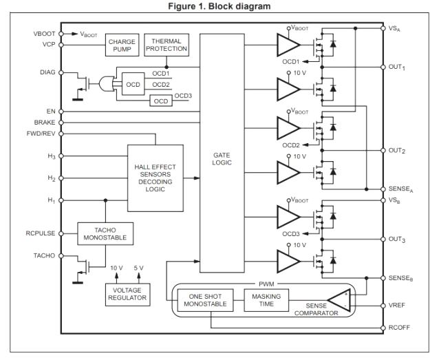
The chips integrates all the circuitry required for effectively driving a 3-phase BLDC motor, as I have explained below:
A 3-phase DMOS bridge, a constant off-time PWM current controller and the decoding logic for single ended hall sensors for generating the essential 120 degree phase shift sequence for the power stage.
With regard to the built-in protections the L6235 device offers a non-dissipative over current protection on the high-side power MOSFETs, protection against ESD, and an automatic thermal shutdown in case the device heats up above the rated value.
50V BLDC Driver Circuit Diagram
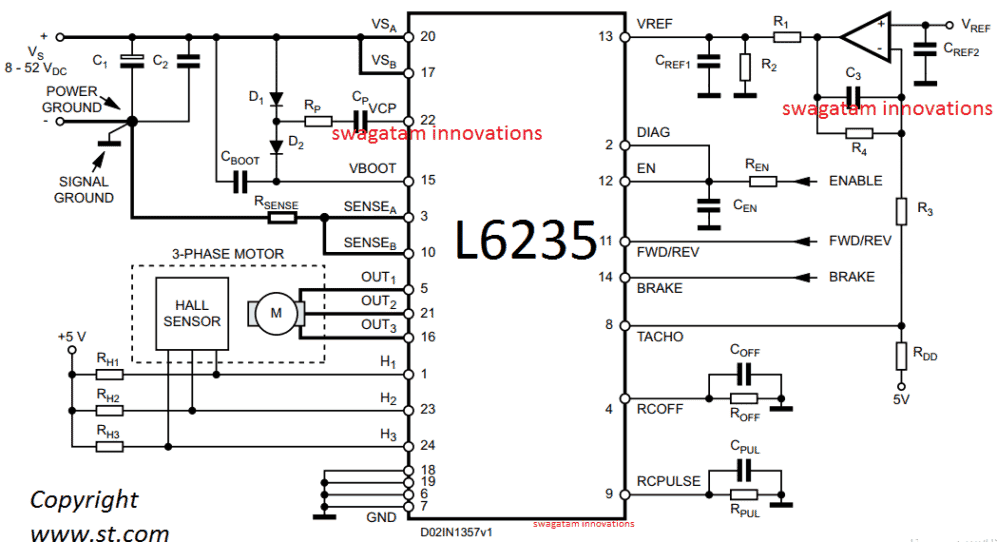
A typical L6235 50V 3-phase BLDC motor driver circuit application can be witnessed above, which looks quite straightforward with its implementation procedures.
You just have to hook up the shown elements in place and use the design to operate any BLDC motor with sensors rated within 8V to 50V at 3 amps rate.
Pinout Details
The pinout function for the specified circuit can be studied from the following data:
Pin#6, 7, 18, 19 = (GND) These are the Ground terminals of the IC.
Pin#8 = (TACHO) It's designated as the open drain output Frequency-to-voltage open drain output. here each single pulse from pin H1 is dimensioned in the form of a fixed and adjustable length pulse.
Pin#9 = (RCPULSE) Is configured like a parallel RC network attached between this pin and the ground, which fixes the period of the monostable pulse responsible for the frequency-to-voltage converter.
Pin#10 = (SENSEB) This pin must be connected together with pin SENSEA to power ground through a sensing power resistor. Here the inverting input of the sense comparator also needs to be connected.
Pin#11 = (FWD/REV) This pinout can be used for changing the rotational direction of the BLDC motor. A HIGH logic level on this pinout will cause a forward motion while, a LOW logic level will allow the BLDc motor to rotate in the opposite reverse direction. For enabling a fixed clockwise or anticlockwise directions, this pinout may be appropriately terminated to a +5V or the ground line..
Pin#12 = (EN) A LOW logic signal will shut OFF all the internal power MOSFETs and stall the BLDC motor. In case this pinout is intended to be not used, it must be terminated to the +5 V supply rail.
Pin#13 = (VREF). You can see an opamp configured with this pinout. The Vref input of the opamp connected with this pinout can be fed with a linearly adjustable 0 to 7V for changing the speed of the BLDC motor from 0 to max. If not used make sure to connect this pinout to GND.
Pin#14 = (BRAKE) A LOW logic level on this pinout will switch ON all highside Power MOSFETs, instantly enforcing the brake/stop function. In case not used, this pinout can be held connected to +5 V.
Pin#15 = (VBOOT) It is simply the input pinout for the bootstrap voltage needed for driving the upper Power MOSFETs. Just connect the parts as indicated
Pin#5, 21, 16 = (3-phase OUT to BLDC motor) Power output which connects with the BLDC motor and powers the motor.
Pin#17 = (VSB) Just connect it as shown in the diagram. Pin#20 = (VSA) Same as above, needs to eb connected as given in the diagram.
Pin#22 = (VCP) It is the output from the internal charge pump oscillator, connect the parts as shown in the diagram.
Pin#1, 23, 24 = 3-Phase sequential signal from the BLDC single ended Hall sensor can be configured with these pinouts, if the BLDC is a sensorless, you can feed an external 3-phase 120 degree apar input on these pinout at +5V level.
Parts List for the above discussed 50V 3-phase BLDC motor driver circuit
- C1 = 100 µF
- C2 = 100 nF
- C3 = 220 nF
- CBOOT = 220 nF
- COFF = 1 nF
- CPUL = 10 nF
- CREF1 = 33 nF
- CREF2 = 100 nF
- CEN = 5.6 nF
- CP = 10 nF
- D1 = 1N4148
- D2 = 1N4148
- R1 = 5.6 K
- R2 = 1.8 K
- R3 = 4.7 K
- R4 = 1 M
- RDD = 1 K
- REN = 100 K
- RP = 100
- RSENSE = 0.3
- ROFF = 33 K
- RPUL 47 K
- RH1, RH2, RH3 = 10 K
For more details you can refer to the following datasheet from ST


Questions & Answers
hai sir , i want constant voltage and constant current 12v to 85v dc 15amp booster converter ckt diagram. battery capacity 12v 63ah.
Hi sreenivas,
Is your battery a li-ion battery or a lead acid?
Hi, can this circiut be used with step/dir signals?
Or what has to be changed?
Hi, I don’t think the above IC has the facility to work with step/dir signal mode.
Which rating transformer suitable sir this project 12v to 75vac 25amp.
75 x 25 = 1875 watts
I do not have a circuit diagram for controlling a 1875 watts BLDC motor…..
850va transformer, 12v to 220ac, turns reduced from after converting primary side 12v to 75vac required amp is 25.
For 220 the current will be 850 / 220 = 3.86 amps
For 75 V the amps will be 850 / 75 = 11.33 amps
hai sir ia m sreenivasulu dammu. sir i have small doughty 500w inverter 12v dc to 220v ac. incase 100ah battery 12v dc to 75v ac conversion primary side amp increased , how much amp will increased so we give 750w bldc e bike motor, we can use this power supply.
sreenivasulu, What is the AMP capacity of the transformer? The wattage can be calculated only if the amp of the transformer is known.
How big is the motor power that can be handled by this circuit?
It can handle a maximum of 50 V 3 amp motor, that’s around 150 watts
do you have a 3 phase circuit to increase the power capacity of this circuit?
i need single phase bldc motor controller ic, can you suggest any ic for single phase bldc motor with good current and voltage capability
sorry I do not have a single phase BLDC motor, by the way I have never seen a single phase BLDC so far…
hello, I applied a 5V to pin FWD/REV and the motor should run in forward direction. However, I am not sure about the wire connection of the motor. What voltage and current waveforms are expected at pin OUT1, OUT2 and OUT3. Below I have some waveforms in two different wire connection (connection A and connection B). May I ask which of the connections has waveforms that make sense? Sorry, I am new to bldc.
https://drive.google.com/drive/folders/1nNvT6F2DhL7MXUaGeopTIFuDkvsA4mHw?usp=sharing
The motor wire connections should be as per the hall effect sequence, hall 1 corresponds to OUT1, hall 2 corresponds to out 2 and so on, you must connect the motor exactly in this way. I am not sure about the waveforms, since I have not built it myself practically.
Good day Mr swag pls do you have any printed circuit board outline for this project or any other high current 3phase bldc motor driver of this kind I would really like to make this on a pcb. Thanks for always helping
Sorry Ifeanyichukwu, I do not have a PCB design for this project!
Dear Sir
I just involved with BLDC. I have a 12-14 Volt High Current Sensored BLDC. (14.4 volt 80 Amper ) . I have to control this motor bidirectional with uC ( Arduino or Pic ) .
How I can increase output current?
Thank you
Regards
Osman
Thank you.
Hello Osman, BLDC operating current can be increased by using powerful MOSFETs for the driver circuit
Dear Swagatam. Shall I connect strong mosfets to outputs with pin # 5, 21, 16 =? If I get into the engine from powerful mosfets. So can I apply the current and voltage I want?
Dear Mehmet, I don’t think that might be feasible since that could involve complex additional circuitry! However there are a few other alternatives that you can try as given in the following links, which could be upgraded externally through more powerful devices.
https://www.homemade-circuits.com/48v-3kv-electric-vehicle-circuit/
or this one
https://www.homemade-circuits.com/make-this-electric-scooterrickshaw/
Çok teşekkür ederim, sevgili Swagatam. Çok naziksiniz.
Benim Zevkim Mehmet!
may i know what is the supply voltage of the op amp? Also, for the heat problem, should I make an opening in the solder mask or adding a larger area of copper pour for GND would be enough for SO24?
the supply to the op amp can be 9V. Heat from which element, MOSFETs?
heat from the IC. i have added a copper area as mentioned in the datasheet (11.2 Thermal management), but the IC still gets very hot
yes the IC will get hot because the power FETs are internal to the IC, so I think a full fledged heatsink may be recommended by some means…
hello, I have some questions about speed control. I built the above circuit with the recommended component values and connect the pot (0V-5V) to the opamp (Vref). When V>2V, not much change of the speed. However, when V<2V, the speed drops and the motor stops quickly.
I want the speed to be proportional to the applied voltage. Do you have any suggestions? Thank you!
hello, It can be difficult to diagnose the fault since most of the processing is internal to the IC. Please double check all the parameters required for the proper functioning of the system, because a single incorrect or missing feed can lead to malfunctioning of the system.
Dear friend,
I am a hobbyist and interested in a supply operated from 2 phases i.e., 415V ac and an output of 12 dc. I tried capacitive circuit but it gets damaged after sometime. Could you help me.
Hello Friend, the capacitor will not get damaged if you use 630 V or higher rated capacitors, please try it with these rating and everything should be fine
Hello,
Thanks for this article. I have a couple of questions about Vref, and would appreciate your inputs.
1. From my understanding of the datasheet, the L6235 has an internal current controller that uses the the voltage drop across the sense resistor and compares that to Vref and drives a PWM internally to produce the required voltage drop. It seems that Vref is essentially a proxy for a desired average current in the motor. The actual current is obtained from the sense resistor, and the internal current controller operates to reduce the error.
2. I am having some trouble interpreting Vref. From the datasheet, Vref is recommended to be between -0.1 and 5V. But in the example given, the motor is a 50V motor. How is this mapping happening?
Hello,
as the name suggests Vref is the reference voltage for the internal error amp. The Vref enables the max current shut down setting for the motor. The internal compartaor opamp uses this Vref reference to compare it with the voltage across the sensing resistor, and switches OFF the driver MOSFETs as soon as the max current exceeds the Vref value.
Hi,
Thanks. I am a bit confused here. I understand that the internal PWM current control compares the Vref and voltage drop across sense resistor and then switch off if the drop exceeds Vref. But this seems a different circuit than the over current protection circuit (I am not sure how the max threshold current for this circuit is being set).
Hi, it is actually a normal over current protection system, since the motor load current has to pass through the sensing resistors. If you see the internal configuration of the IC, you will find that the internal power MOSFET source terminals are connected with the senseA senseB terminals, which means the entire MOTOR current has to pass through the common sensing resistor. The max current can be set by using a resistor which will develop a voltage higher than the set reference voltage value.
R(sense) = (Motor voltage Rating – Supply voltage) / Max Motor current Rating
Hi, I have a question about the L6235. I am using the L6235 Evaluation Board to drive a bldc with hall sensors. Unfortunately, the motor won’t start, no matter what I try. It’s almost like the motor stalls before spinning, because current flows through the motor but it simply doesn’t spin. The motor I am using is a small gimbal motor with 3 hall sensors. The current spikes to 2 amps and the rotor locks, but it doesn’t rotate. I’ve tried all combinations of the phase wires and hall wires.
Do you have any suggestions on what I can try in order to troubleshoot it?
Hi, did to configure pin14 with the positive supply? And what input did you provide to the Vref?
Hi Swagatam, thanks for the quick reply. On the L6235 eval board, I applied positive voltage to the enable pin, brake pin, and Vref pin. I tied the fwd/rev pin to ground. I also tried using PWM on the Vref signal, but the motor would only make a humming sound. Applying 3.3v to the Vref pin is how I got the motor to draw current, but it is stalled.
I also tied the brake pin to ground, but this wasn’t the issue.
Does the Vref pin require PWM signal?
Thanks Tim, The Vref will need a linearly varying voltage, not a PWM. You can simply achieve this by connecting a 1k potentiometer with the Vref. The outer terminals of the pot should be connected with the DC supply rails, and the center terminal with the Vref. Adjusting the pot should now enable the required speed control on the motor.