The proposed 3 LED battery level indicator can be typically used for monitoring a 12 V lead acid battery charge level, through 3 distinct LED illumination. The entire circuit is built using just a couple of BJTs , a few zener diodes, resistors and LEDs.
Different Ways to Check Battery Voltage
A hydrometer is perhaps the most efficient way to examine the condition of a lead acid battery. Hydrometers, on the other hand, have a variety of disadvantages. Because they're constructed of glass, they're delicate and can be dangerous to use while driving.
The tiny quantity of battery acid which persists on them poses a storage issue since the droplets and vapors corrode most metals and substances. These may be good for a garage, however justifying their cost for the rare usage in house workplaces is often not practical.
Measuring the voltage with load connected is yet another way to verify the battery's status. Under a typical functional load, a lead-acid car battery in an acceptable state of charge (Soc) will have a voltage level between 11.6 and 14.2 volts. When a battery's voltage level falls beneath 11.6 volts, its capacity is drastically reduced, and it discharges fast.
This situation might not allow to turn the starting motor for too long, most of the time! If the voltage on load, on the other hand, is more than 14.5 volts, the battery is completely charged!
If it stays in this condition for an extended period of time while the car is being driven, the alternator-regulator system may go faulty, and the battery could well be destroyed due to overcharging.
There are several methods for determining the battery voltage. A digital panel meter arranged as a voltmeter might be used. However, their disadvantage is that they are approximately 10 times more expensive than a hydrometer!
Using a 'expanded-scale voltmeter' is another best option.
A squint-and-peer practice is required to display the voltage range between 11 and 15 volts on a meter front, calibrated at 0-16 volts. It's even worse on a 0-30 volts scale, which is common on contemporary multimeters.
A meter that measures 11 volts at the lower end of the scale and 16 volts at the extreme end of the scale works perfect. As a result, the phrase 'extended-scale' is coined.
However, you wouldn't want to be staring at a meter on the dashboard while driving in traffic. The voltage range in which your battery is most effective is just about 2 volts.
What is actually required is an indication that only takes a passing glance and does not require any 'analysis.' That's precisely what we've tried to accomplish in this project.
Making a 3 LED Indicator
We created a simple 3 LED battery indicator circuit that displays the following:
- Yellow indicates that the battery is 'low'.
- Green indicates that the battery is in good condition.
- Red indicates that the battery has been overcharged.
A yellow indicator illuminates when the battery voltage falls below 11.6 volts. This implies that the battery is either undercharged or that a large load (such as high-powered driving lights) is draining too much power.
When the voltage is between 11.7 and 14.2 volts, the green LED light turns on, indicating that everything is well.
When the red indicator illuminates, which it would if the voltage exceeds 14.2 volts, the vehicle's voltage regulator may need to be adjusted, or there may be another issue.
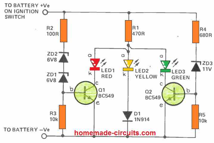
Circuit Description
The working of this 3 LED battery indicator circuit is dependent on the varying voltage drops across the different color LEDs.
The voltage drops across red, yellow, and green LEDs at 20 mA are generally 1.7V, 3.0V, and 2.3 volts. Q1 and Q2 are turned off by R3 and R5 when the vehicle battery voltage becomes extremely low for either ZD1/ZD2 or ZD3 to conduct.
The yellow LED is forward biased and conducts through D1 under these conditions, generating a voltage of roughly 3.7 volts at point A. (see circuit diagram). ZD3 starts conducting as soon as the supply voltage increases over 11.6 volts, biasing Q2 on. The green LED illuminates due to its low forward voltage specs, lowering the voltage at point A to around 2.6 volts.
Because this isn't enough to turn on D1/LED3, the yellow LED turns off. The yellow LED's bias is 'stolen' by the green LED.
Q1 is biased on when the supply voltage exceeds 14.2 volts, and the red LED 'robs' the bias from the green LED. The red LED alone conducts when the voltage at point A drops to two volts.
The current via the LEDs is limited by R1. The Q1 base currents are limited by R2 and R4.
Another Simple Design
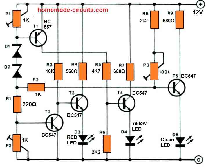
Just three LEDs are utilized to indicate the battery state of the automobile (or boat). The LEDs are lit in the following manner:
D3 – 12 volts
12…13 V = D3 + D4
D4 = 13…14V
D4 + D5 > 14 V
Preset P2 determines the voltage at which D3 turns off (13 V); PI determines the voltage at which D4 turns on (12 V); and P1 determines the voltage at which D5 turns on (13 V) (14 V).
Because the different changes influence each other, the setting up procedure is very important and will need to be done multiple times. The author's prototype is shown in the image.



Questions & Answers
Yes electricity is dangerous but when working with 12 Vdc there is no danger what-so-ever.
Sir, I fixed a Bluetooth in my 2 strokes bike. I fixed a 4ah 12v lead asid battery. From head light connection through a Diode and buck converter to battery. I want to fix battery charge level circuit with water proof in simple way. which is good for bike. Please, tell me.
Hi Sundar,
For getting accurate results you can try any of the circuits explained in the following article, as per your choice:
https://www.homemade-circuits.com/3-step-dc-voltage-level-monitor/
sir please help to make battery charger indicator as follow current sense and if current not pass than off indicator, means show the charging status only if possible please make With Op-amp
gurmeetwarwal@gmail.com
Hi Gurmeet, you can try one of these circuits for your applications, the LOAD is supposed to be your batery:
https://www.homemade-circuits.com/how-to-sense-current-using-op-amp-low-side-and-high-side-circuits-explained/
Hi Swagatam
I decided to start with your original circuit (ref below) but needed to make a few changes as my specs are little different to yours;
1. As I am using a RBG Tri-colour LED with common cathode I needed to moved the LEDs to the emitter side (left R1 in possition)
2. Using a high intensity LED so changed R1 to 680 ohms
3. Changed ZD1 and ZD2 according to the following criteria
RED: > 13V
BLUE: 11.1 – 13V
GREEN: > 13V
All works well and get the crossovers at the correct voltages except that the Red and Blue LED’s never really turn off (especially the Red) which does not make for clear distinctions.
What changes can I make to improve this aspect?
Kind regards
Thank you Michael,
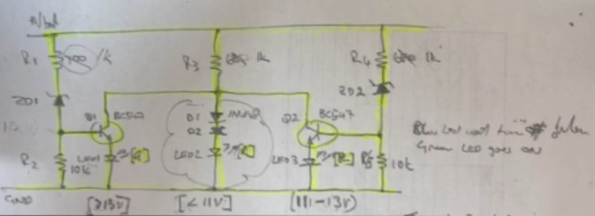
I saw your diagram in my email:
Can you please try increasing the value of the R3 to maybe 2.2k or higher and check if that helps to shut off the blue LED above 13V.
Hi
I have got it to work including a flashing circuit for the Red (low voltage) LED.
Emailed you my circuit diagram fyi and any improvements.
Thanks again for all your assistance.
It Looks amazing! thank you so much for sharing your circuit with us…all the best to you.
Apologies, changed R4 instead of R3, 5k1 seems to work but need to tweak the DZ as the voltage set point changed.
Please ignore previous comment
OK, so now is everything working as required?
Unfortunately made no difference at all, even tried 3k3 and 5k1. When using 10k it did not come on
In that case it seems the LED at the emitters of the NPN will not work…I will try to design an appropriate circuit using RGB LED, soon, and let you know…
Hi Mike, I guess you are referring to the circuit diagram which is explained in the above article.
In this diagram the LEDs must be attached to the collector side of the transistors.
However as you are saying that at the emitter side it works good, but red and blue LEDs never turn off, so that is strange, because at the emitter side the voltage will be minimal and will not allow the LEDs to glow properly.
So the LEDs will actually not illuminate at all or illuminate very dimly.
And at the emitter side, the voltage will be 0.6V lower than the base voltage of the respective transistor which means the LEDs will hardly glow??,
Can you please show me the connection diagram for your design…you can send it to my email ID for further analysis…
Hi
Did you get my diagram?
I added an additional Diode to the red (middle) led circuit and that worked for the red led led turning off when the blue (rhs) led turns on (11-13V) but the blue led does not turn off when the green (lhs) led turns on.
I need to use a RGB tri-colour led with common cathode as only have space for a single led in my application.
I did not get your circuit diagram. Please send it to the following email:
homemadecircuits
@gmail.com
Hi Swagatam, just what I am looking for but need to modify for a 12V LiFePO4 battery on a golf cart as follows and using a bi-colour LED (R & G with common cathode) as do not have space for 3 LED’s in the handle.
Red (Low) if Vb below 11V; Green (full) if Vb above 13V and Yellow (i.e. both R & G) LEDs on if Vb 11.1 – 13V.
If possible to also include a cut off (will drive a relay) to turn the controller off when Vb below 10V.
Looking forward to you reply
Hi Mike,
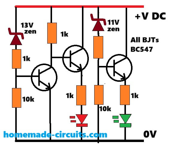
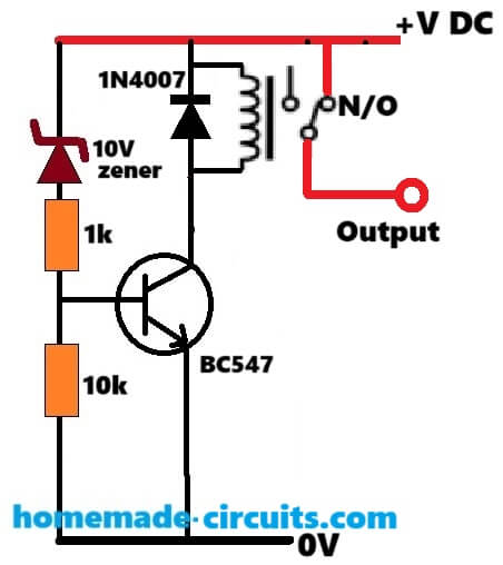
I have designed the circuit for you as per your specifications, as shown below, You can tweak the zener values to get the exact response as required.
For the relay cut-off you can employ the following circuit separately:
Awesome, thanks very much Swagatam
You are most welcome Mike.
Hi Swagatam, having a closer look at the circuit it seems that the condition of when Vb = 11 – 13V both LED’s should turn on i.e. yellow/orange colour (remember I am using a R&G bi-colour LED with common cathode).
Also could one make the Red LED flash for the cut off condition (Vb < 10V)?
Hi Mike, yes, the circuit is designed to enable red/green both LEDs ON between 11V and 13V.
Until the 13V transistor is turned ON, the RED LED keeps glowing, then after 11V is crossed, the 11V transistor kicks-in and turns ON the Green LED….
So between 11 and 13V both red and green remain lit together. Below 11V green stops glowing, and above 13V the red LED stops glowing.
Making the RED LED flash could make the circuit a bit complicated, since we will require an additional LED flasher circuit for that.
Thanks again, at the cut off stage, the Red LED will be on anyway.
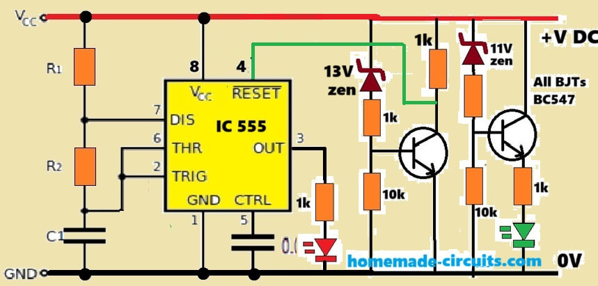
The reason for the flashing is that the user will know why it has stopped working. What about a 555 timer?
Ok, please try the following design and let me know if it works or not:
Thanks again, will do
What are the values for R1 and R2 as well as C1 and C2?
Sure, no problem! The R1, R2, C1 values decides the flashing rate of the LED, whose values can be determined through any online “555 astable calculator software.”
…C2 can be a 0.01uF capacitor.
Hello i need to modify the first circuit for red led on from 3-13v then went off after wards yellow ON from 13-till 17v and went off then green ON from 17-20v can you tell how this can be achieve? using simple electronic. The LED i am using is 4 terminal common anode
Sorry, the first circuit cannot be modified for these operations, you will need an opamp circuit or this.
can you share any op amp circuit for 3 LED with voltage
You can try the first diagram from the following article:
https://www.homemade-circuits.com/3-step-dc-voltage-level-monitor/
Hi Mr Swagatam;
My charger input 220AC and output 72V 8A. I have repaired it and would like to test it. To my opinion
I will reduce the current (for instant 8A to 6A) to protect the mosfet. If that reasonable and correct approach then what sould I do please advice?
Hi Suat,
Do you have a current control stage in the SMPS? then you can set it to allow only upto 6 Amp current. However, the MOSFET current will depend on your output load. It will be activated only when an output load is connected.
Alternatively, you can connect a 40 watt incandescent bulb in series with the input AC supply to restrict the current.
Thanks.
circuit flow parts;
input: uc3845-tr8550-20A mosfet
output: fast diode-t431-utc358 / 14 pins level leds driver and a thyritor(BT153)-kind regards.
UC3845 has a current control stage, you can refer to the following article which shows an SMPS using UC3845.
The P2 preset adjusts the max current level:
https://www.homemade-circuits.com/adjustable-0-100v-50-amp-smps-circuit/
Hi Mr Swagatam;
On my 72V battery charger circuit there are double optocouplers and when I remove one of them I see doubled higher voltage about 170V than expected 84V at the secondary side of the circuit.
And although there is 84V at the secondary side when I remove the capacitor then I see too lower voltage about 2V instead of 84V. My main problem is I never see 84V at the load output(battery connection point) although capacitor has 84V.
In case I would not be able to fix it I will add an external circuit using 84V directly from the capacitor and also I will add an auto cutoff loop to the external circuit. It is posible for you to make any comment on the matter? Thank you a lot.
Hi Suat,
The opto coupler is used in the feedback network to control the output voltage at a specified level, that is why removing the opto coupler is causing the output voltage to get uncontrolled and rise to a higher value.
There may be a diode in the output line which may be causing the 84V to drop to a lower level, you can try extracting the 84V directly from across the capacitor to access the full 84 V.
You can also add an auto cut off circuit externally with the output, no issues.
Hello Mr Swagatam;
I have 72V battery charger. Output has 6 leds. Respectively, one is on/off led and the rest 5 leds show the saturation level of the battery.(%20 to %100)
There is no power at the output (due that BT153 is not active) but all leds light(as if charge level is %100).
I have no 72V battery at home to test it. It is possible to test for instant by connecting three 220V
bulb in series instead of 72V battery?
Hello Suat,
Are you trying to attach a load at the output of the battery charger to check for the voltage drop and the response of the LEDs?
In that case yes you can attach a single 220V bulb, because using 3 in series would require 220 x 3 = 660V V supply..
Thanks for the rapid support when a single 220v bulb is attached stil all the leds light. I think 82V is present at the output but negative is not (capacitor has DC 82V at the output side).
Consewuently, BT153 should be inactive which is driven by UTC358 or other IC that has 14 pin and drives the 5 charge level leds too. I need to follow the path.
When you connect s discharged battery, it causes the charger output supply to drop and align with the battery low voltage level, which causes the LEDs to adjust accordingly as per the voltage drop level. If your charger output is not dropping then all the LED indicators will continue to glow together.
I applied 32V to the output terminals while 220 AC input is unplugged and again all the leds are lighted. Then it should be perceiving all time as if it is fully charged.
However you think that 82V at the outputd capacitor is adequate voltage to duly charge the 72V battery?
In that case it seems the LED level detector is not working correctly. For a 72V lead acid battery, the correct full charge voltage should be around 84V, 82V V will not be optimal.
Good evening sir, I have a problem I would like to get an electrical circuit working in such a way that when a power supply sends an input current, that charges a 12v battery and at the same time supplies the parallel circuit, then stops supplying the battery when it is loaded. All this added to the fact that in the absence of power, the 12v battery powers this parallel circuit.
Hello Jason,
You can try the first circuit from the following article:
https://www.homemade-circuits.com/opamp-low-high-battery-charger/
Please if I want to combine the op amp battery charger circuit with automatic cutoff with the first voltage control circuit of the 03 leds in this page how should I do?
You can simply connect the 3 LED circuit across the battery terminals.
Merci beaucoup
Hello sir can the first or last circuit work in a 24v battery or it’s only for 12v? Do u have for a 24v that indicates battery level? Thanks
Hello Morris,
you can try the first circuit from the following article:
https://www.homemade-circuits.com/4-led-temperature-indicator-circuit/
Just replace the R10 with a 10K preset.
You can use 24 V in this circuit.
Hello Sir
I would like to ask a question. it is about designing a test equipment. There is a circuit board that needs to be tested. The board consume 24VDC and 6A ( short time)supply current and voltage . There must be two indicators as well as LEDs, one green and other red, if it has fault on the board, it should be flashing red leds. if it has no fault, then it will display normal green led. If you can share any idea with me , it would be great .
Thanks for your understanding
Hello Abhishek, how do we know there’s a fault in the board?
thank you very much for your reply
the board is already installed. at the output it is connected to the fan(24V/DC) and a heater(short time 2 to 6A). If the fan and heater doesn’t work, there we have an error on the board. the probabilities error we have to build up by a circuit.If it sometimes occur on the board can be short circuit or contact between components feet. If everything works well (fan and heater), then green LED should be displayed. If there is an error (short circuit or overvoltage or undervoltage), then red LED should be displayed.
Thank you for urs Understanding
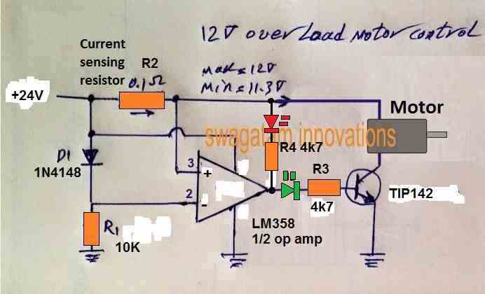
The over voltage indicator may not be required, because when an over over voltage happens the motor will start drawing more current and the situation will convert into an over current or over load. But this circuit will not show an under voltage, for that you may have to employ another op amp.
The circuit has a transistor to control the over current situation for the motor. If you don’t want this feature, you can remove the transistor and connect the green LED 4k7 with the ground line.
Here’s a simple current controller which you can modify according to your needs:
Hi Swagatam,
I’ve been struggling with a small problem which seems to me should be simple but apparently isn’t.
I have an old R/C transmitter (Circa early ’80s) that has an analog meter on it. I’ve learned that it takes about 3V to get full scale deflection, and that the internal resistance is about 2.8k. I am using a LiFeP04 two cell battery to power the transmitter, which gives about 7.2V on a full charge, but is basically flat at about 5.6V. I would like to hook up the meter to the battery so that it will read full deflection when the battery is at 7.2V and zero at around 5.6V. The voltages aren’t set in stone but I’d like something vaguely close. It doesn’t need to be super accurate, it just needs to give me an indication if it’s safe to fly or not. I guess anything less than about half (or maybe a third) would be a hint that it might be advisable to pack up and go home.
I know nearly nothing about electronics, so I’m really just looking for a recipe I can follow to hook it up.
All advice gratefully received.
😉 Ian
PS apologies if this query is too far off topic for this article. It was the closest I could find.
Hi Ian,
you can reduce the sensitivity of the 3 V FSD meter by connecting a shunt resistor across its terminals. You can apply 7.2V and experiment by connecting different value resistors parallel to the meter terminals until the meter needle just settles at the full scale deflection.
You can try resistors between 0.1 ohm to 1 ohm and check which resistor actually fulfills the requirement.
Hi Swagatam and thanks for you quick reply. I’ll try your suggestion.
😉 Ian
Hi Ian, I am sorry, the above suggestion is actually suitable for stepping down current, not voltage. For stepping down voltage you will need to attach a voltage divider with your meter as demonstrated in the following diagram: