A shunt resistor is a very low value, high wattage resistor which is connected in parallel to a low range meter, so that it helps the meter to substantially increase its measuring capacity.
Quite often you might find it hard to measure large currents with a contemporary multimeter. If you've ever considered buying an industrial shunt to address the issue, you're aware of how costly these can be. While industrial shunts are quite accurate, they typically cost more than the circuit they may be monitoring!
However, there is a simpler and less expensive option that could perform equally well in the majority of cases: You can construct your homemade shunts with a few pennies worth of wire and just a little technical expertise. It simply takes a few minutes and can be a lot of fun!
What is A Shunt?
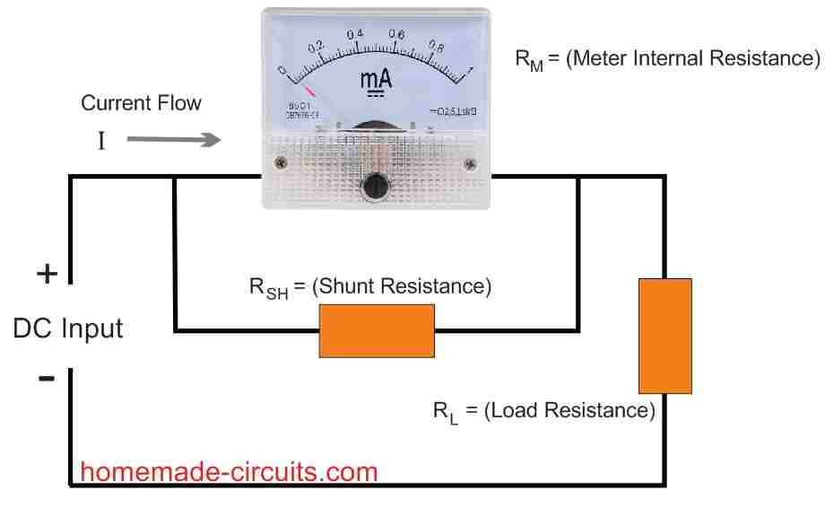
A shunt is just an extremely low-value resistor (often less than an ohm) which is used to assist in the measurement of current. As seen in Fig.1, a shunt resistor RSH is connected in parallel with a meter to reduce its sensitivity by a set value.

The shunt does this by bypassing or "shunting" the bulk of the current flowing past the meter. As a result, the shunt resistor allows you to convert any cheap conventional meter, such as a 0 -1 milliammeter, into, perhaps, a robust 0 to 20-amp meter.
Selecting the Shunt Meter
Before trying to make your own shunt, you must first procure an appropriate shunt meter. When choosing a meter, look for one that is in good working health and has an appropriately calibrated scale on the front.
For instance, if you require the meter to measure 10 amps full scale, choose a meter with a scale ranging from 0 to 1.
Choose one with a 0 to 3 graduation if you want a full scale measurement of 30 amps.
Shunt Meter Resistance
To construct a shunt, you'll have to know your meter's internal resistance.
As a result, choose a device which has its internal resistance labeled on it. Most often this will be in small characters on the meter front or around the terminals on the backside.
Assuming you already have a meter but don't know what its internal resistance is, there's a quick method to find out. Take your digital multimeter (DMM) and set to its maximum resistance range. Connect the red (positive) lead of the DMM to the positive terminal of the analogue meter and the black (common) lead to negative terminal of the analogue meter.
By sending a tiny amount of current through the equipment under test, digital multimeters can determine their internal coil resistance.
This type of measurement should not be attempted with an analogue multimeter. These anaogue multimeters test resistance with a lot greater current, which might possibly harm some of these.
Now, keep testing through the lower DMM's resistance ranges (remember, you started with the maximum) until you see the analogue meter's needle reaching a full-scale reading.
Take a note of the value on your DMM and jot down with a marker pen on the back of the meter. Be cautious, and do this procedure carefully. It's easy to destroy the mA meter if you move too fast and unintentionally pin it.
How to Build the Shunt Resistor
A small piece of copper wire is used to create the shunt. Because any wire will show some resistance, we can utilize this feature to build a shunt resistor.
To construct the shunt, you must first calculate the amount of current that could travel through it. If your meter is capable of measuring 20 amps full scale, for example, the shunt wire should be capable of securely carrying this magnitude of current.
Let's assume you want to construct a 20-amp shunt out of a surplus analogue 0-1 milliammmeter with a 0-1 graded faceplate.
Select the most suitable gauge wire from any copper-wire chart on the internet. It's important to remember that the lower the wire gauge, the bigger the diameter and the more current it is able to safely handle.
250 circular mils per amp is more than enough for most amateur applications. Divide the circular mils for the chosen wire (available in the copper wire chart) by the maximum current you decide to use through the wire, to determine the circular mils per amp value for the shunt wire:
Circular Mils per amp = (circular mils for wire) /(current through the wire)
A 12 -gauge wire has a cross-sectional area of 6530 round mils, according to the copper wire chart. We obtain 326 circular mils/amp by dividing this by 20 amps, which should be sufficient. Wire in the 12-gauge range is widely available and may be found at most hardware stores. Next, you can use the following formula to get the shunt's resistance:
RSH =RM /(n -1)
Where RSH shows the shunt resistance, RM represents the resistance of the analogue meter, and n signifies the shunt's multiplication factor.
In our set up, because a 0-1 milliammeter is being employed and 1 milliamp = 0.001 amps, n = 20 amps /0.001 amps, or 20,000.
Now, let's assume that the internal resistance of your analogue meter was determined to be 81 ohms. Inserting this resistance value and n = 20,0000 into the above Equation gives:
RSH = 81Ω/(20,000-1) = 0.00405Ω
That resistance looks quite small isn't it? A shunt with such resistance is suitable for the passage of approximately 20 amps through it. And for a full-scale deflection, this will enable 0.001 amps (1 mA) to flow through the meter.
The length of our shunt must now be calculated. Remember that 12-gauge wire provides a resistance of 1.619 ohms/1000 ft, as indicated in the copper-wire chart. As a result, the length of the shunt wire (LS) may be calculated as follows:
LS = RSH/( x Ω/1000 ft) = 0.00405/(1.619Ω/1000 ff.) = 2.5 ft
With a 0-1 mA meter employed, having an internal resistance of 81 ohms to measure 20 amps full scale, the 12-gauge shunt wire should be 2 feet 6 inches long.
Now the contact resistance of the meter can create issues with a shunt wire of this length. Considering the very shunt resistance of 0.00405 ohm, even a solid solder connection may exhibit a lot of resistance.
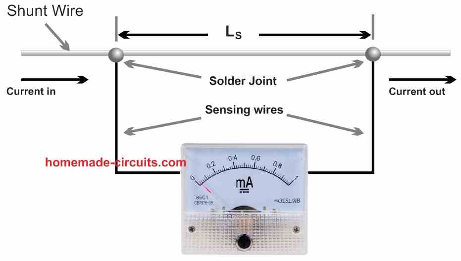
A couple of sensing wires are needed to ensure that the circuit's contact resistance is not included in the shunt resistance. On the shunt wire, these sensing wires are placed LS apart, as illustrated in Fig. 2.

The sensing wires can be made of any type of wire; which is not crucial. This little effort can considerably improve your shunt's precision.
We're all set to make our shunt now.
Cut a three-foot piece of 12-gauge solid copper wire. With a pocket knife, peel the insulation off the wire, ensuring not to break it. Next take a 2 inch measurement through one end and solder one sensing wire there.
Measure 2 ft 6 in from this sense wire and solder the other sense wire in place. As illustrated in Fig. 2, hook up the shunt to the desired ammeter and you're ready to read current! If you wish to make the shunt a bit smaller, wound it around the handle of an insulated screwdriver or some such identical object, for example a wooden splinter.
How to Calibrate the Shunt
This technique can produce highly precise shunts. But higher precision could be obtained, by calibrating the shunt to a reference sample, such as a calibrated meter.
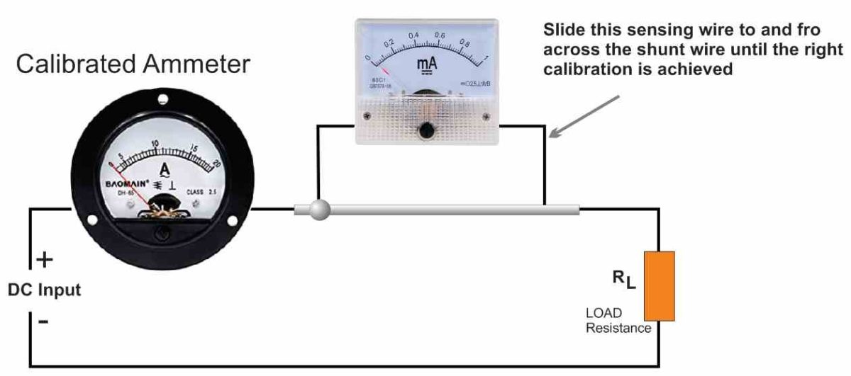
To do this, construct the circuit seen in Fig. 3. Confirm that the load resistance, RL, is capable of securely handling the power.

The author discovered that car tail lamp bulbs can be applied as an excellent load for the circuit. Connect one sensing wire into position as stated above to calibrate the shunt.
Switch ON power to the circuit and shift the right side sensing wire up and down across the shunt wire until the meter connected across the shunt wire indicates the exact same current as the calibrated meter on the left.
Turn off the power to the circuit and connect the second sensing wire exactly at that spot.
Reference: https://www.learningelectronics.net/VA3AVR/gadgets/shunts/shunts.html
This is exactly what I did when I needed to build a test meter for work. To avoid making an inductor that would be slamming the meter with back EMF when I removed power, I measured the length of one turn around the coil form and divided this amount into the length of wire. Two and one-half divided the wire evenly. So when I wound the coil I wound 2 1/2 turns clockwise then bent the wire to reverse direction and wound 2 1/2 turns counterclockwise. Bent the wire again and wound CW, etc. There is no inductance in the coil of wire and the meter has served me for over 30 years.
Thank you for the interesting feedback, much appreciated!