In this article I have compiled 10 interesting yet simple LED chaser circuits, which not only create beautiful running light effect but are also easy to build.
These primarily incorporate LEDs as well as mains operated bulbs through triacs. The proposed circuit is transformerless and is thus a lot compact and light weight.
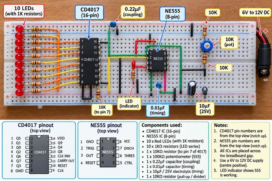
Which LED Chaser Circuit Should You Choose?
In this article you will find different types of LED chaser circuits which can be built using popular ICs like the IC 555, IC 4017 and 74LS164. Each circuit produces a different type of running light effect. The following guide below will help you to select the right circuit for your requirement.
- For a simple running LED effect: You choose the basic IC 555 and IC 4017 LED chaser circuit.
- For controlling more than 10 LEDs: You may choose a circuit using two or more IC 4017 stages, depending on the required LED count.
- For the Knight Rider scanning effect: Grab the Knight Rider LED chaser circuit which produces a scanning light pattern.
- For a fading LED effect: You may go for a fading LED chaser circuit that gradually increases and decreases the brightness of the LEDs.
- For different LED sequencing patterns: You can choose a suitable 74C164 or 74LS164 based circuit.
- For forward and reverse LED movement: You may select the reverse-forward LED chaser circuit designed for this effect.
- For controlling LED lamps or bulbs: Choose a circuit specifically designed for the required load and supply voltage. Check the output driver ratings before connecting the load.
| Your Requirement | Recommended circuit |
|---|---|
| Simple running LEDs | 555 + CD4017 |
| More than 10 LEDs | Two CD4017 ICs |
| Knight Rider scanning effect | 555 + CD4017 with diode network |
| Gradually fading LEDs | LED chaser with transistor stages |
| Different sequencing patterns | 74C164 or 74LS164 |
| Forward and reverse movement | Reverse/forward LED chaser |
Before building any of these circuits, you must always check the supply voltage, component values and maximum output current specified for that particular design.
How Does an LED Chaser Circuit Actually Work?
An LED chaser circuit is a simple electronic circuit which makes a group of LEDs glow one after another. This gives you a running light effect which is used in decorative lights, car lights and many other electronic projects.
A simple LED chaser can be made using IC 555 and IC 4017. The IC 555 produces clock pulses and the IC 4017 uses these pulses to switch its output pins ON one by one. When LEDs are connected to these outputs, then they start glowing one after another and produce the chasing effect.
The chasing speed can be changed by adjusting the resistor or capacitor values connected with the IC 555. Other types of LED chaser circuits use different ICs and components to produce special effects like forward and reverse running lights, scanning lights and fading LEDs.
Below given are different LED chaser circuits which you can try building according to your requirement. Some circuits are simple, while others use more components to produce different types of running light effects.
1) Basic 10-LED Chaser Circuit (555 + CD4017)
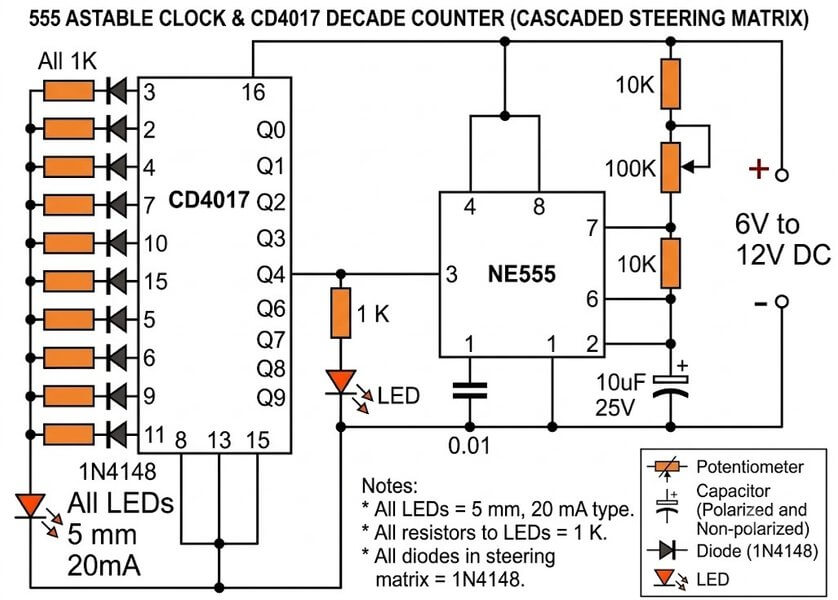
How it works: This is the ultimate beginner-friendly running light project. It uses a standard 555 timer IC wired as a clock oscillator, sending steady pulses directly into a CD4017 decade counter IC. The 4017 takes those clock ticks and turns its 10 output pins ON one by one in a clean, continuous loop.
Main features: You get a smooth 10-LED chasing sequence that works anywhere from 6V to 12V DC. Speeds are fully adjustable—just turn the 100k speed control pot to speed up or slow down the running effect. LEARN MORE...
2) 18-LED Cascaded Chaser Circuit (Dual CD4017)
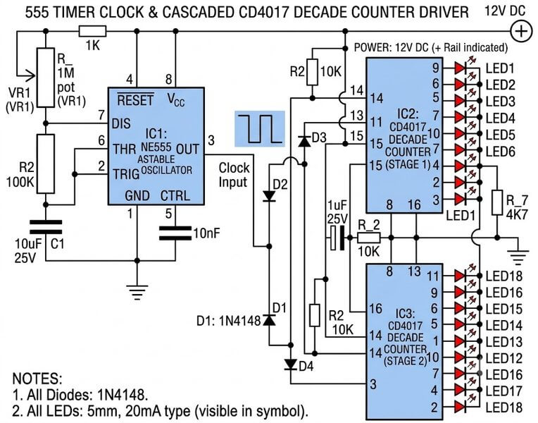
How it works: A single CD4017 chip can only handle 10 steps, but when you need a longer running line, you can link two 4017 ICs together.
The 555 timer provides the main clock heartbeat. Once the first 4017 finishes counting through its pins, it passes the duty over to the second IC.
Main features: Uses a few steering diodes hooked between the two counter chips to handle the handover logic seamlessly.
This lets you run 18 LEDs sequentially without needing microcontrollers or writing software code.
3) 100 to 200 LED Forward-Reverse Chaser (Diwali & Christmas Decorative Lights)
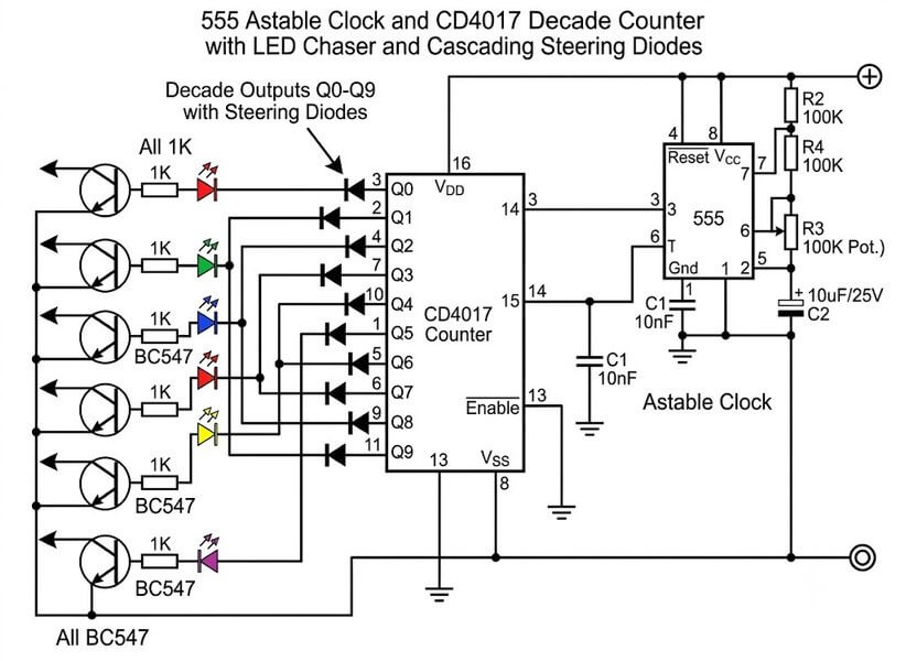
How it works: Basic chasers are fun on a breadboard, but festive lighting for Diwali or Christmas demands a lot more power and bigger arrays. This circuit expands standard sequencing by adding heavy-duty transistor driver stages.
Main features: Instead of just cycling in one boring direction, the lights travel forward to the end and then reverse back toward the start. Depending on the power supply and transistor setup, you can hook up massive strings from 100 up to 200 LEDs. LEARN MORE...
4) Dual-Mode LED Chaser with Flashing Blinker Effect
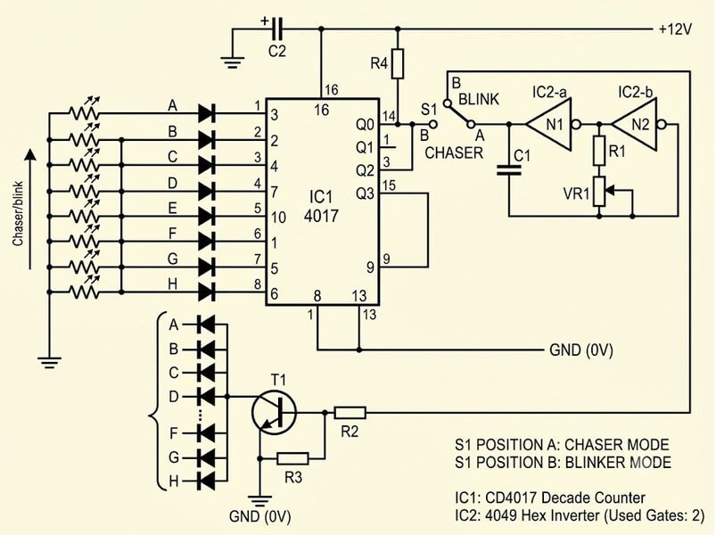
How it works: Designed to answer a popular reader request: having one circuit that can chase and flash. It combines together a standard running sequencer with a master bypass line connected to a selector switch.
Main features: Flip the toggle switch to mode one and the LEDs run sequentially one after another. Flip it to mode two, and the chasing stops while all LEDs begin flashing together in a full-bank strobe effect. LEARN MORE...
5) Center-Out Outward Chasing LED Circuit
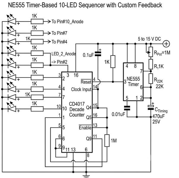
How it works: Most chaser designs move left to right, but this setup changes the visual routine entirely.
By cross-wiring output pairs from the middle of the LED strip outward, the lighting starts right at the center.
Main features: As clock pulses arrive, the light bursts symmetrically outward toward both ends at the same time.
It gives a striking spreading-light effect that looks great on custom display signs and automotive panels. LEARN MORE...
6) KITT Scanner Knight Rider LED Chaser
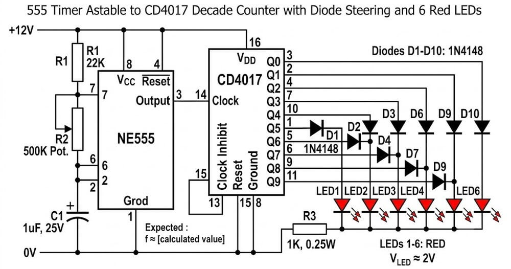
How it works: Inspired by the iconic scanning red light on the front of the KITT car from Knight Rider. It pairs the trusty 555 timer and 4017 decade counter with a simple matrix of 1N4148 signal diodes.
Main features: The diode matrix routes output pulses so a group of 6 LEDs lights up back and forth in a smooth, continuous scanning motion.
No programming needed...just pure hardware logic. LEARN MORE...
7) Slow Adjustable Fading LED Chaser Circuit
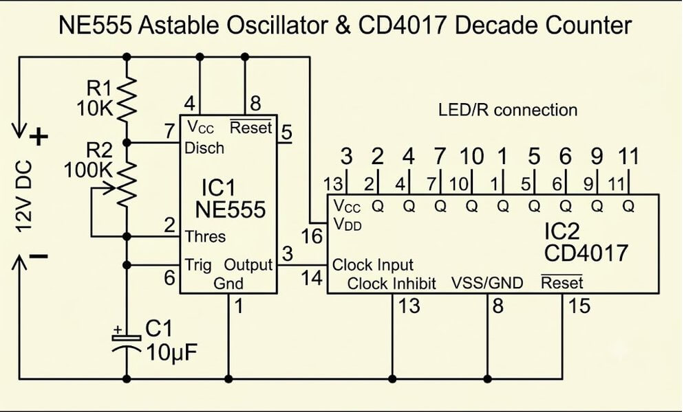
How it works: Standard digital chasers snap LEDs ON and OFF instantly. If you want a softer, more elegant look, this circuit places discrete BJT transistor stages and charging capacitors at each LED output.
Main features: As each output triggers, the capacitor charges and slowly fades the LED up, then slowly discharges to fade it down.
This creates a smooth, gentle lighting transition ideal for mood and decorative displays. LEARN MORE...
8) 8-Bit Shift Register LED Chaser (74C164 + 4011)
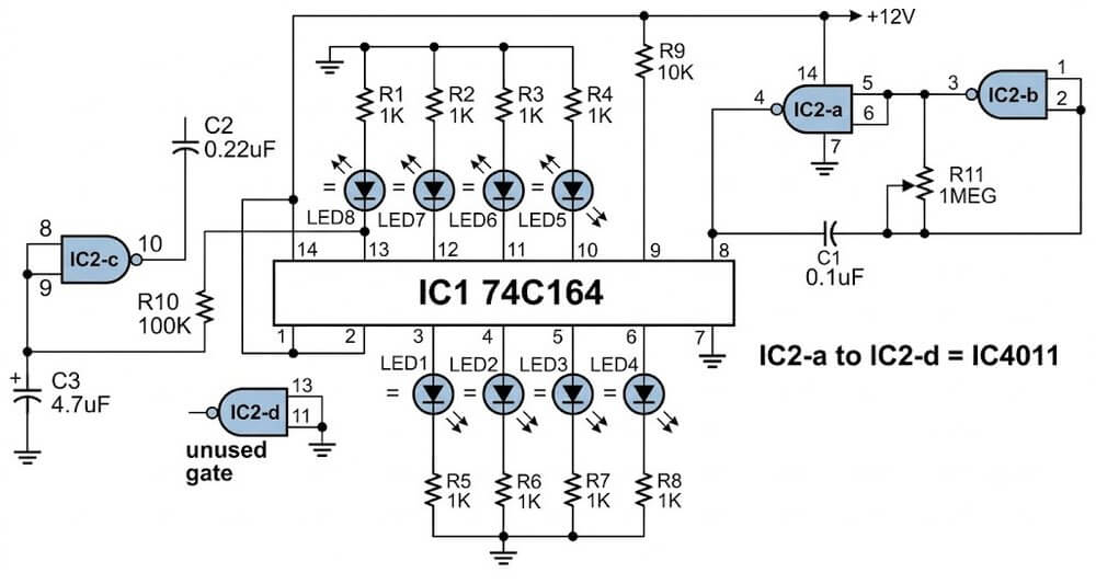
How it works: An alternative way to build a running light display without using a 4017 counter. It uses a 74C164 8-bit shift register IC paired with a 4011 quad CMOS NAND gate IC acting as the clock pulse generator.
Main features: Shifts a bit across an 8-LED sequence continuously.
An RC network on the reset pin makes sure the board clears its memory and restarts the cycle cleanly every time it hits the 8th step. LEARN MORE...
9) Dual 74LS164 Center-Meeting LED Bar Chaser
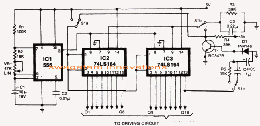
How it works: An advanced shift-register circuit built with two 74LS164 ICs and a 555 clock timebase. The logic is wired so that bits shift inward from opposite ends of the display board.
Main features: Two glowing light points start on the outer edges, travel toward each other, and meet right in the middle.
A quick transistor reset stage then clears the line so the cycle can start over. LEARN MORE...
10) 16-Step Bidirectional Chaser Circuit (IC 40193 + IC 4514)
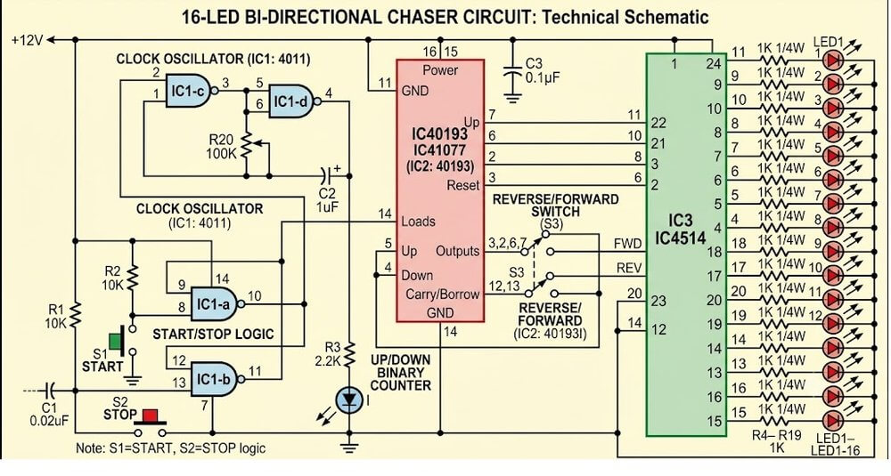
How it works: For high-step sequencing without microcontrollers, this setup replaces the 4017 with a 40193 up/down binary counter and a 4514 1-of-16 decoder IC.
Main features: A simple NAND gate latch handles direction changes automatically.
You get a full 16-step forward-and-reverse running sequence with total stability and no programming required. LEARN MORE...
Common Problems in LED Chaser Circuits
Sometimes an LED chaser circuit may not work properly after building it. So following are some common problems and the things you can check.
Fault#1: LEDs are not glowing
First check the power supply and make sure the positive and negative connections are correct. Also check the IC pin connections, LED polarity and any loose wires on the circuit.
Fault#2: All LEDs are glowing together
Check the wiring of the IC outputs and make sure the LEDs are connected according to the circuit diagram. A wrong connection can stop the normal chasing action.
Fault#3: LEDs are chasing too fast or too slow
In circuits using an IC 555 timer, the chasing speed depends on the timing resistor and capacitor values. Check these components and adjust them according to the circuit design.
Fault#4: Some LEDs are not glowing
Check the polarity of those LEDs and inspect their connections. Also check whether the required current limiting resistors are fitted correctly.
Fault# 5: The circuit works for some time and then stops
Check the power supply voltage, loose connections and any components that may be overheating. If transistors are used to drive many LEDs, you make sure they are not being overloaded.
Always disconnect the power before checking or changing any wiring. If the circuit operates from mains electricity, do not touch the circuit while it is connected to the supply.
How you can Add more Number of LEDs in a Chaser Circuit?
Sometimes you may want to connect more LEDs to a chaser circuit than what is shown in the diagram. This is possible in some circuits but the method will depend on how the circuit is designed. For example the IC 4017 has 10 decoded outputs, so it can control 10 chasing steps in its normal arrangement.
Now if we want more steps then we may need to add another IC 4017 and connect it nicely with the first IC. So just connecting more LEDs to the same output will not increase the number of chasing steps.
In circuits which uses shift register ICs we can also add more ICs to increase the number of LEDs in the sequence. But the extra connections you must do correctly for the circuit to work as expected.
We must also check the power supply current. When more LEDs are added then circuit may need more current. If the IC output cannot supply the required amount of current, we may have to use extra transistors to drive the LEDs...
So before you add more LEDs, first of all you have to check the circuit diagram and the IC output limits, do not simply connect extra LEDs without checking the current, or else the IC or other components may get damaged.
Which is your Favorite LED Chaser?
So guys, that's it! These were a handful of interesting and cool LED chaser circuit designs and compilation, which provides you with varied options of creating your own LED chasing effect without depending on any microcontroller ICs. So which one did you like? Do let us know in the comment section, and if you have any issues with the circuits, do not hesitate to ask them through your comments.

Questions & Answers
check the 4017 circuit with a 12V DC adapter and see if the sequencing is working or not.
a cell phone charger output will also work for verifying the sequencing.
you will have to connect the triac MT1 and MT2 pins with AC mains supply and the bulbs as indicated in diagram.
request indicate c code for 12 led chaser for suitable pic with fading effect.comet tail
sorry i don't have it presently with me.
I've made the 12V car version. I've only left out the leds before the mosfets. But it's not working. When I don't connect the positive wire going to the 22k resistor, port 8 and 4 of ic555 and to port 16 of ic4017. All the light are burning, but when i connect this positive wire nothing is working at all. Have you any idea what could be wrong and how i can check it?
that's weird, because without the positive supply connected the LEDs would never light up.
I think there's something terribly wrong with your connections or the components.
Separate the 555 and the 4017 stages….build and test them separately, once the results are confirmed you can try integrating them as per the diagram.
how many 5w 230v bulbs can be put in single triac in parrel? is there any triac for large watt handling?
100nos if the triac (BT136 etc) is mounted on a heatsink, for more bulbs you can try other higher rated triacs.
sir
mene apka 2 no. circuit try kiya.lekin jo 12 v hai o kam nehi ker raha he.12 v adopter use kerne par sequence proper nehi a raha hey. plz help me sir…
try connecting 1k resistors across gate and ground of all the triacs.
sorry sir,
apne samay nikal kar mere prashna ka jabab diya,lekin kam ke bajese me try nehi kar saka.
aj mene try kiya led negetive se 1k lagaker GND se connect kiye.lekin 12v 2amp smps se sequence tut raha he. plz sir help me.
sir,
triac ke gate aur GND par 1k connact kene par sequence sahi arahahe thanks. lekin triac 100w bulb flash nehi ker rahaye. No.1 chanel se sirf flash ho raha he, lekin lumin kam ho raha he.
me ne 1k ke jaga 220E resistance se triac ke gate connect kiye,lekin No.1 chanel chor ke baki sab off he.lumin thora sa change huya lekin baki kam nehi ker raha he.
sir triac pin-1-T1.pin-2/tab-T2
pin-3-G.circuit me to is hisab se nehi he….sir plz help me…..
remove the shown capacitive power supply and try with a 12V adapter as the power supply and check the response..
sir
mene 12v 2amp adapter use kiya.led sequence sehi aarahahe.lekin triac kam nehi kerrahahe.no.1 chanel kam ker rahahe100w bulb lagane par lumin kam ho rahahe.baki ke 5 chanel off he.
connect a LED with 1k resistor from pin3 of IC555 to ground, it should flash, if it doesn't then the fault could be assumed to be in the 555 circuit, other wise the fault could be in your 4017 circuit….make sure all the LEDs at the gate of the triacs are connected correctly and illuminate for enabling the triacs to conduct.
thanks sir
circuit sahi se kam ker rahahe.1k ke badle mene 220E resrstor triac gate se connect ki ya aur apke bataye huye,1k resistor gate aur circuit GND se connect kerne par led sequence sahi a rahahe.aur triac proper kam ker rahahe.sab chanel 100w lamp se try kiya lumin sahi a raha he.
sir mene triac pin 1-A1 aur pin 2-A2 hisab se lagaya. thanks sir guide karne ke liye.
you r great……..
Glad to know it's working, you are welcome Orrie!
Sir on this circuit how much nos of 8mm or 5mm white leds can run
basit, divide the supply voltage with the LED forward voltage this will give you the number of LEDs that can be connected in series on each channel.
Great article, thank you.
My question is can you reverse it, have the LEDs on all the time and the circuit shut them off in sequence.
thanks, that would be possible with a normal IC 4017/555 chaser circuit without the forward reverse facility….there you can achieve it by simply reversing the LED polarity….I am not sure how it could be done in the above circuits….may be by reversing all the diodes an LED polarity, but I am not very sure.
Hello sir
How i connect 1 W*5 LED to this circuit
Hello Sandeep,
see the last circuit, you can replace the bulbs with the LEDs with a series resistor.
The mosfets can be replaced with a TIP 122 transistor as an alternative.
You can connect 3nos of 1 watt LEDs with a resistor on each transistor
Hello sir
How can I connect 1W*5 LED to above circuit
Swagatam sir
the power of your circuit is wrong, it will not work, please you see in the 2nd picture
i have corrected it, please check it now….
i am telling you after check and i can prove it
and i am telling you that please check in circuit
capacitor, diode and Zener diode put in the wrong direction in your second picture circuit
You can see this circuit
The transistor stage is not required, the triacs can be driven directly from the IC, as shown in the second circuit
triac is fitted in the way your circuit but do not get that way for the entire supply triac and because of which fully AC supply cannot send. so will need to use transistors
now you make your circuit and used
and then some comment
Sir good finally you have improved in your second picture
but sir you need improve in circuit other part
सर जी क्या मैं C 0.47uf/400V की जगह पर कोई और C use कर सकता हूँ सर जी अगर कोई और C हो तो बता दो पर circuit के लिए सुरक्षी हो 🙂
you can 105/400V cap
Thank you sir for help me
yes it will
sir मैं इस प्रोजेक्ट से हट कर एक सवाल पूछ रहा हूँ क्या मैं BTA41,BT139 और BT136 को Thyristor (SCR) की तरह use कर सकता हूँ
Rakesh,
What exactly are you planning to make?
Aap kya banana chahte ho pehle wo batao
yes you can use triacs in place of SCRs in projects such as this:
https://www.homemade-circuits.com/2016/01/8-function-christmas-light-circuit.html
Thank you sir for help me
Dear sir how to make Triac Dimmer but operated by other circuit
Dear Rakesh, please explain more. which "other circuit"
Dear sir मेरे other circuit का कहने का मतलब है के दुसरे circuit द्वारा प्राप्त output voltage 0 से 0.8 DCV 200uA dimmer के लिए कम जादा कर सकते है जो की Triac को Triac Dimmer बनाने के लिए पर्याप्त नहीं है
तो मैं आपसे ये जानना चाहता हूँ triac को dimmer बनाने के लिए अभी कौन कौन से components की जरुरत पड़ेगी ?
Dear Rakesh.
0.8V will need to be amplified first with a 12V amplifier circuit or an optocoupler circuit….the output from this optocoupler can be used for driving the triac.
MOC3063 can be used for this.
Dear sir 240V AC में, मैं अगर सिर्फ एक 1N4007 diode का use न्यूटल या फेस कर तो मुझे output voltage कितना मिलेगा ?
Please tell me sir
dear Rakesh, the output will be 120V DC average, but the peak will be around 310V DC
Dear sir आपने जो output बताया है मुझे इसी voltage से BTA41 को ऑपरेट करना है कैसे करूँ कोई ऐसा हल बताइए जो circuit के लिए सेफ हो
Please sir
connect a 1k resistor to triac gate and then connect a 0.33uF/400V capacitor and connect this capacitor end with the 120V input….also connect a diode 1N4007 parallel with the capacitor….cathode will be towards the 120V source.
Dear sir please drow this circuit for me
please please sir i request you
My mail id rakeshmauryaup@gmail.com
It's very simple…connect 120V input with the band side of a 1N4007 diode, connect the other side of the diode with 1K resistor, connect the other end of the 1K with the SCR gate.
after this connect a 0.33uF/400V capacitor right on the leads of the 1N4007