• Skip to main content
  • Skip to primary sidebar

Homemade Circuit Projects

Need circuit help? Post them in the comments! I've answered over 50,000!

Blog | Categories | About | Hire Me | Contact | Calculators-online
You are here: Home / Battery Charger Circuits / 12 V to 19 V Boost Converter Circuit

12 V to 19 V Boost Converter Circuit

Last Updated on May 17, 2026 by Swagatam 11 Comments

In this post I have explained how to build a simple 12 V to 19 V boost converter circuit which can used to charge a 19 V battery from a 12 V car battery.

Table of Contents
  • How the Circuit Works
    • PCB Design

The main application of this circuit could be for the charging of a laptop battery from a car battery,
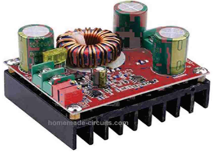
Prototype image of the 12 V to 19 V Boost Converter Circuit

How the Circuit Works

The 12 V to 19 V converter circuit diagram can be seen in the following figure.

The working principle is actually very straightforward.

A free-running astable oscillator is employed to operate a voltage doubler circuit.

A series pass transistor is used to regulate the output voltage, which is controlled by a comparator. The earth connections for the input and output lines is the same and is common with the negative of the 12 V supply source.
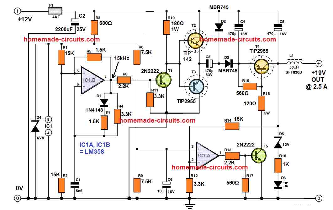
12 V to 19 V Boost Converter Circuit Diagram

IC1B becomes the main active part of the the astable multivibrator configuration. Capacitor C1 and resistor R4 which are connected across the feedback path provide a working frequency of 15 kHz roughly.

Diode D1 and resistor R7 make sure that the square wave output operates with a 50:50 duty cycle.

C1 capacitor must be a good quality capacitor with high stability and low temperature coefficient features, a ceramic type capacitor should do the job well.

The dode D1 should be rated with a temperature characteristics so that the output square wave is maintained correctly all the time regardless of the output load conditions and circuit heating.

Transistors T2 and T3 gets switched alternately through the square waves generated by the IC1B.

When T3 is in the switched ON period, capacitor C3 charges up to 12 V by means of D2. Next, while the T3 goes into the switched OFF period, causes T2 to turn ON, which enables the negative terminal of C3 to be instantly linked with the +12 V supply.

However, in this situation the charge stored inside in C3 is unable to change immediately, therefore as soon as the C3 negative terminal gets linked with the high 12 V potential, it becomes necessary for its positive terminal to also step up.

The situation causes the C3 positive terminal to get ‘boosted up’ to approximately two times the supply voltage.

In real life operation , due to the losses occurring through the diodes and transistors essentially mean that the output cannot be exactly two times the supply input level, rather will be a slightly below the expected 2X level.

Schottky diodes are employed in the circuit to ensure that the forward voltage drop is kept to the minimum. D3 is used for rectifying the voltage and C4 is configured to store the rectified output from the diode.

Make sure to use very high quality capacitor for C3 since it will be solely responsible for delivering the entire output current to the load. The regulation for the output voltage is executed by op-amp IC1A.

The potential divider created by the resistors R14 and R12 detects the T4 collector voltage and then IC1A compares it with the reference voltage generated from the network comprising of the parts R6, R9 and zener diode D4.

The level of the stepped up 19 V output can be fixed by adjusting the value of R14. A 15 kΩ value for R14 will provide an approximate output voltage of 19 V.

The ripple voltage content of the 19 V output at full load will be as shown in the next figure.
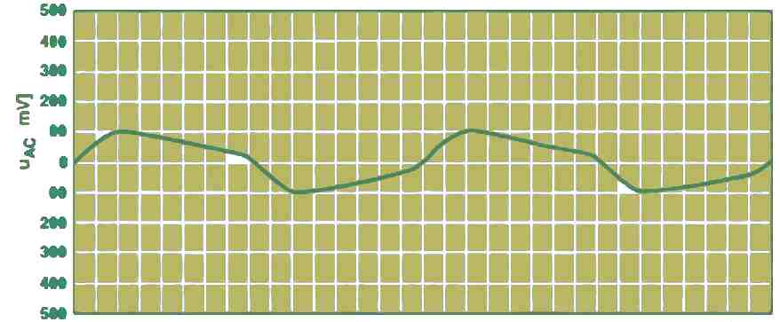
ripple voltage content of the 19 V output at full load

If the capacitor value C6 is increased, will ensure that the reference voltage goes up at a very slow rate when power is first switched ON. This feature can provide this 12 V to 19 v converter circuit a nice soft-start or slow-start characteristic. This switch-on delay can be verified by looking at the LED D6.

PCB Design

The complete PCB design and the components overlay diagrsm is shown in the following image:
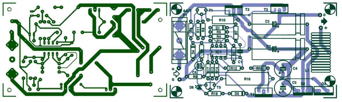
PCB Design for the 12 V to 19 V Boost Converter Circuit

You'll also like:

  • water2BheaterSolar Water Heater Circuit with Battery Charger
  • lowbatteryindicatorcircuit 2Low Battery Indicator Circuit Using Two Transistors Only
  • LC Resonance Calculator for EV Battery Charger Circuits
  • supercapacitorchargercircuitSuper Capacitor Charger Theory and Working

Filed Under: Battery Charger Circuits Tagged With: Boost, Converter

About Swagatam

I am an electronics engineer and doing practical hands-on work from more than 15 years now. Building real circuits, testing them and also making PCB layouts by myself. I really love doing all these things like inventing something new, designing electronics and also helping other people like hobby guys who want to make their own cool circuits at home.

And that is the main reason why I started this website homemade-circuits.com, to share different types of circuit ideas..

If you are having any kind of doubt or question related to circuits then just write down your question in the comment box below, I am like always checking, so I guarantee I will reply you for sure!

Previous Post: « High Stability of Crystals in Oscillator Circuits
Next Post: 6 Simple AC Bridge Circuits Explained »

Reader Interactions

Questions & Answers

Total Posts: 11
Newest Oldest
rick
September 24, 2026 • 2 weeks ago #212668

hello mr.swagatam
i would like to make the output of the converter 19V 5 A ,what should i do?

Reply
SwagatamAdmin
September 24, 2026 • 2 weeks ago #212675

Hi Rick,
You can probably achieve that by replacing the TIP2955 with MOSFET IRF9540, and by using 1 mm thick wire for the inductor, and replacing R15 with 1k, R16 with 10 ohms

Reply
Rashid abdallah
November 30, 2024 • 2 years ago #166308

swagatam please you try to design a 12v DC to 19v DC converter that can charge a laptop and be used if possible in a television but please try to make to circuit a little bit very okay and simple

Reply
SwagatamAdmin
December 1, 2024 • 2 years ago #166338

Hello Rashid, you can try the concept presented in the following article:
https://www.homemade-circuits.com/12v-car-laptop-charger-circuit-using/

Reply
Rich
March 18, 2023 • 4 years ago #141116

Would like parts list for the 12 volt to 19 volt step up converter, that would be clean enough for a television needs to be 19 volts 2.1 amps output.

Reply
JACK SHUBERT
October 30, 2022 • 4 years ago #134186

will you please suggest a circuit. 1. Control the speed of travel and the distance of travel of a linear actuator, (powered by a low current 12 VDC motor).. 2. Eliminate the use of mechanical limit switches and the typical DPDT reversal switch These functions being done by solid state circuitry.What comes to mind is circuitry using a controlled flip flop using IC 555’s and two power supplies, plus and minus 12vdc.

Reply
SwagatamAdmin
October 30, 2022 • 4 years ago #134194

Hi, It seems you have posted the question under the wrong article. Please post it under a “motor control” article.

Reply
Happie
August 11, 2022 • 4 years ago #132222

Hello sir can you please design boost converter that support 1200watt load and output maximum 42v I want to boost 12v to 40v with minimum 38v 15ah output for my e-bike thanks..

Reply
SwagatamAdmin
August 11, 2022 • 4 years ago #132228

Hello Happie, you can try the following design:
https://www.homemade-circuits.com/high-power-dc-to-dc-converter-circuit-12-v-to-30-v-variable/
However at 38 V 1200 watts the current output will need to be 1200/12 = 100 amps. This will require a Li-ion battery rated at 150 Ah minimum.

Reply
gopi
May 7, 2021 • 5 years ago #89048

Solar Panel – Shark 440 – Mono Perc, 144 Cells, Half Cut Specifications
wattage (Wp)=440 watts
voltage at max power=42 volts
current at max power=10. 5 amps
open-circuit voltage=50 volts
short circuit current=11 amps
i want to use the above panel to charge the 60v electric bike is there any simple circuit sir please see the below video for your understanding.

Reply
SwagatamAdmin
May 8, 2021 • 5 years ago #89067

Gopi, you will need a boost converter for this.

The following circuit can be used if the transistors are appropriately modified for 60 or 100V rating:

ebike 60 V boost charger circuit

Reply

Need Help? Please Leave a Comment! We value your input—Kindly keep it relevant to the above topic! Cancel reply

Your email address will not be published. Required fields are marked *

Primary Sidebar

My YouTube Channel

Circuit Simulator: Draw and Simulate Schematics

circuit simulator image

Categories

  • Arduino Projects (95)
  • Audio and Amplifier Projects (134)
  • Automation Projects (18)
  • Automobile Electronics (104)
  • Battery Charger Circuits (90)
  • Datasheets and Components (109)
  • Electronics Theory (151)
  • Energy from Magnets and Earth (43)
  • Games and Sports Projects (11)
  • Grid and 3-Phase (20)
  • Health related Projects (27)
  • Home Electrical Circuits (13)
  • Indicator Circuits (16)
  • Inverter Circuits (98)
  • Lamps and Lights (161)
  • Meters and Testers (72)
  • Mini Projects (28)
  • Motor Controller (68)
  • Oscillator Circuits (30)
  • Pets and Pests (15)
  • Power Supply Circuits (91)
  • Remote Control Circuits (50)
  • Security and Alarm (65)
  • Sensors and Detectors (107)
  • SMPS and Converters (46)
  • Solar Controller Circuits (62)
  • Temperature Controllers (44)
  • Timer and Delay Relay (51)
  • Voltage Control and Protection (44)
  • Water Controller (37)
  • Wireless Circuits (31)

Subscribe to get New Circuits in your Email

Other Links

  • Privacy Policy
  • Cookie Policy
  • Disclaimer
  • Copyright
  • Videos
  • Sitemap

People also Search

555 Circuits | 741 Circuits | LM324 Circuits | LM338 Circuits | 4017 Circuits | Ultrasonic Projects | SMPS Projects | Christmas Projects | MOSFETs | Radio Circuits | Laser Circuits | PIR Projects |

Recent Comments

  • Swagatam on Inverter Circuit with Feedback Control
  • Swagatam on How to Make Step Down Transformers
  • Jerry Adeosun on Inverter Circuit with Feedback Control
  • Pedro Lima on How to Make Step Down Transformers
  • Martins Vita on Understanding IC 4043B, IC 4044B CMOS Quad 3-State R/S Latch – Working and Pinouts

Social Profiles

  • Twitter
  • YouTube
  • Instagram
  • Pinterest
  • My Facebook-Page
  • Stack Exchange
  • Linkedin

Calculators

  • ZVS Induction Heater + Tank Calculator Tool
  • Zener Diode Calculator
  • Wire Current and Thickness Calculator (Ampacity Calculator)
  • Voltage Divider Calculator
  • Transistor Base Resistor Calculator
  • Transistor Astable Multivibrator Calculator
  • TL431 Calculator
  • Solar Panel, Inverter, Battery Calculator
  • Ferrite Core Air Gap Calculator Tool
  • Parallel MOSFET Calculator Tool: How to Connect MOSFETs in Parallel Safely
  • LC Resonance Calculator for EV Battery Charger Circuits
  • LED String Series Resistor Calculator
  • PFC (Power Factor Correction) Calculator Tool: 3kW
  • Passive Power Factor Correction (PFC) Calculator
  • LM567 IC Calculator Tool
  • SMPS Flyback Boost Converter Calculator
  • Shunt Resistor Calculator for Ammeters
  • SCR and Triac Gate Resistor Calculator
  • Battery Back up Time Calculator
  • Boost Converter Calculator (Non-Isolated)
  • Bootstrap Capacitor Calculator
  • Buck Converter Calculator
  • Buck-Boost Converter Calculator
  • Capacitance Reactance Calculator
  • DCM Flyback Transformer & Wire Gauge Wire Size Calculator Tool
  • Filter Capacitor Calculator
  • IC 4047 Calculator (Frequency and PWM)
  • IC 4060 Calculator
  • IC 555 Astable Calculator
  • IC 555 Monostable Calculator
  • IC SG3525, SG3524 Calculator
  • Inductance Calculator
  • Induction Heater Inductor and Resonant Frequency Calculator
  • Induction Heater Work Coil Calculator
  • Inverter LC Filter Calculator
  • LC Resonance Calculator
  • LED Current Calculator
  • LM317, LM338, LM396 Calculator
  • NAND/NOT Gate RC Values Calculator
  • NOT, NAND Gate Frequency Calculator
  • Notch Filter Calculator Tool
  • Ohm’s Law Calculator
  • Phase Angle Phase Shift Calculator
  • Power Factor (PF) Calculator
  • RC Filter Calculator
  • Reactance Calculator
  • Sine Table Calculator for SPWM Arduino Code
  • Small Signal Transistor(BJT) and Diode Quick Datasheet
  • SMPS Calculator for Toroidal Ferrite Transformers
  • SMPS Flyback Transformer Calculator – Design by Target Duty Cycle
  • TL431 Calculator
  • Op-Amp Hysteresis Resistor Calculator

© 2026 · Swagatam Innovations