• Skip to main content
  • Skip to primary sidebar

Homemade Circuit Projects

Need circuit help? Post them in the comments! I've answered over 50,000!

Blog | Categories | About | Hire Me | Contact | Calculators-online
You are here: Home / Arduino Projects / Arduino Tachometer Circuit for Precise Readings


Arduino Tachometer Circuit for Precise Readings

Last Updated on June 8, 2026 by Swagatam 4 Comments

A tachometer is a device that measures the RPM or angular velocity of a rotating body. It differs from speedometer and odometer as these devices deal with linear or tangential velocity of the body while tachometer a.k.a. “tach” deals with more fundamental the RPM.

Table of Contents
  • Introduction
    • Prerequisites
    • Concept of Interrupts
    • Components required for this Tachometer project using Arduino
    • Circuit Setup
    • Programming
    • Know the code

Introduction

Tachometer is composed of a counter and a timer both of these working together provides the RPM.In our project we are going to do same, using our Arduino and some sensors we will setup both a counter and a timer and develop our handy and easy tach.

Prerequisites

Counter is nothing but a device or setup that can count any certain regular occurring event like passing of a dot in disc while in rotation. Initially the counters were built using the mechanical arrangement and linkages like gears, ratchets, springs etc.

But now we are using counter having more sophisticated and highly precise sensors and electronics.Timer is an electronic element that is able to measure the time interval between events or measure time.

In our Arduino Uno there are timers that not only keep track of time but also maintain some of the important functions of Arduino. In Uno we have 3 timers named Timer0, Timer1 and Timer2. These timers have following functions-• Timer0- For Uno functions like delay(), millis(), micros() or delaymicros().

• Timer1- For the working of servo library.

• Timer2- For functions like tone(), notone().

Along with these functions these 3 timers are also responsible for generating the PWM Output when analogWrite() command is used in the PMW designated pin.

Concept of Interrupts

In Arduino Uno a hidden tool is present which can give access to a whole lot of functioning to us known as Timer Interrupts.Interrupt is a set of events or instructions that are executed when called interrupting the current functioning of the device, i.e. no matter what codes your Uno was executing before but once an Interrupt is called Arduino execute the instruction mentioned in the Interrupt.
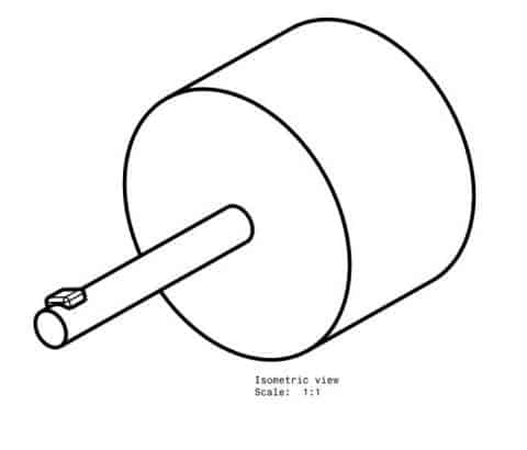
magnet on motor shaft

Now Interrupt can be called at certain condition defined by the user using an inbuilt Arduino Syntax.We will be using this Interrupt in our project that makes our tachometer more resolute as well as more precise than the other Tachometer project present around the web.

Components required for this Tachometer project using Arduino

• Hall Effect Sensor (Fig.1)
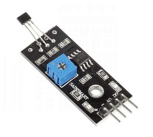
hall effect sensor module

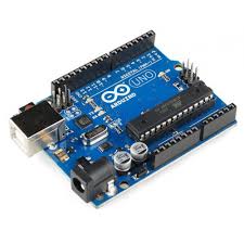
• Arduino Uno

Arduino UNO board

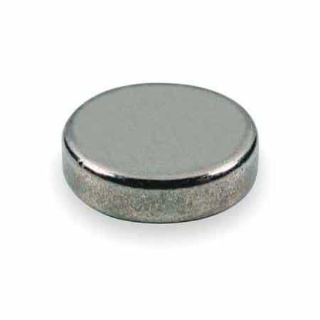
• Small magnet

small magnet

• Jumper wires

• Rotating Object (Motor shaft)
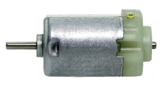
DC motor

Circuit Setup

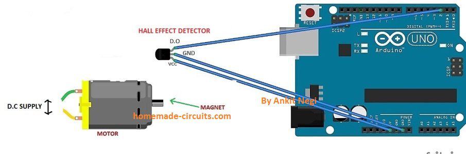
• The setup for creating is as follows-

• In the shaft whose rotation speed is to be measured is fitted with a small magnet using glue gun or electrical tape.

• Hall Effect sensor has a detector in front and 3 pins for connections.

• The Vcc and Gnd pins are connected to 5V and Gnd pin of Arduino respectively. The Output pin of the sensor is connected to the digital pin 2 of the Uno to provide the input signal.

• All components are fixed in a mount board and Hall detector is pointed out from the board.

Programming

int sensor = 2;                 // Hall sensor at pin 2
volatile byte counts = 0;       // Must be volatile (used in ISR)
unsigned int rpm = 0;           // RPM is always positive
unsigned long previousTime = 0;

void count_function()           // ISR
{
  counts++;                     // Increment pulse count
}

void setup()
{
  Serial.begin(9600);            // Initiates Serial communication
  pinMode(sensor, INPUT);

  previousTime = millis();       // Initialize timer
  attachInterrupt(digitalPinToInterrupt(sensor), count_function, RISING);
}

void loop()
{
  delay(1000);                   // Update RPM every second

  detachInterrupt(digitalPinToInterrupt(sensor));

  unsigned long currentTime = millis();
  unsigned long timeDiff = currentTime - previousTime;

  if (timeDiff > 0)              // Safety check
  {
    rpm = (60UL * 1000UL * counts) / timeDiff;
  }

  previousTime = currentTime;
  counts = 0;                    // Reset counter

  Serial.print("RPM = ");
  Serial.println(rpm);

  attachInterrupt(digitalPinToInterrupt(sensor), count_function, RISING);
}

Upload the code.

Know the code

Our tachometer uses Hall Effect Sensor; Hall Effect sensor is based on Hall effect named after its discoverer Edwin Hall.

Hall Effect is phenomenon of generation of voltage across a current carrying conductor when a magnetic field is introduced perpendicular to the flow of current. This voltage generated due this phenomenon help in Input signal generation.As mentioned Interrupt will be used in this project, to call Interrupt we have to setup some condition. Arduino Uno has 2 conditions for calling for Interrupts-

RISING- When used this, Interrupt are called every time when the Input signal goes from LOW to HIGH.

FALING-When used this, Interrupt are called when signal goes from HIGH to LOW.

We have used the RISING, what happens is that when the magnet placed in the shaft or rotating object come close to Hall detector Input signal is generated and Interrupt are called in, Interrupt initiates the Interrupt Service Routine(ISR) function, which include increment in the counts value and thus count takes place.

We have used the millis() function of Arduino and previoustime (variable) in correspondence to setup the timer.

The RPM thus is finally calculated using the mathematical relation-

RPM= Counts/Time taken Converting the milliseconds to minutes and rearrangement we gets to the formula= 60*1000/(millis() - previoustime)*counts.

The delay(1000) determines the time interval after which the value of RPM will be updated on the screen, you can adjust this delay according to your needs.

This value of RPM obtained can be further used to calculate the tangential velocity of the rotating object using the relation- v= (3.14*D*N)/60 m/s.

The value of RPM can also be used to calculate the distance travelled by a rotating wheel or disc.

Instead of printing values to Serial monitor this device can be made more useful by connecting a LCD display (16*2) and battery for better usage.
You'll also like:

  • crystal tester compressedSimple Crystal Tester Circuit
  • f2Bto2Bv3 Frequency to Voltage Converter Circuits Explained
  • MeasuringmVUsingIC741Circuit252CDiagramAC Millivolts Meter Circuit Using IC 741
  • IMG 20170904 143144Line Follower Robot Circuit using Arduino

Filed Under: Arduino Projects, Meters and Testers Tagged With: Arduino, Precise, Readings, Tachometer

About Swagatam

I am an electronics engineer and doing practical hands-on work from more than 15 years now. Building real circuits, testing them and also making PCB layouts by myself. I really love doing all these things like inventing something new, designing electronics and also helping other people like hobby guys who want to make their own cool circuits at home.

And that is the main reason why I started this website homemade-circuits.com, to share different types of circuit ideas..

If you are having any kind of doubt or question related to circuits then just write down your question in the comment box below, I am like always checking, so I guarantee I will reply you for sure!


Previous Post: « Stepper Motor Driver Circuit using IC 555
Next Post: Digital Capacitance Meter Circuit Using Arduino »

Reader Interactions

Questions & Answers

Total Posts: 4
Newest Oldest
Sharoj Al Hasan
August 14, 2017 • 9 years ago #52413

Sir
Can u give me a circuit
Which can auto cutt of When Volt below 4 v

i need this circuit for 9v rechargeable battery

Reply
SwagatamAdmin
August 14, 2017 • 9 years ago #52422

Sharoj,

4V cannot be the lower threshold for a 9V batt, it should be 8V,

anyway you can try the second design from the following design:

https://www.homemade-circuits.com/2012/07/make-6v-4ah-automatic-battery-charger.html

Reply
sharojalhasan
August 12, 2017 • 9 years ago #52370

Dear

please give me a circuit diagram That uninterup Dc power supply 9v volt.
battery 3.7 volt . Power supply 5v

if power supply gone then Power supply will be continue to my 9v modem by battery …

Reply
SwagatamAdmin
August 12, 2017 • 9 years ago #52373

you can refer to the following design

https://www.homemade-circuits.com/2013/03/simple-dc-ups-circuit-for-modemrouter.html

Reply

Need Help? Please Leave a Comment! We value your input—Kindly keep it relevant to the above topic! Cancel reply

Your email address will not be published. Required fields are marked *

Primary Sidebar

My YouTube Channel

Circuit Simulator: Draw and Simulate Schematics

circuit simulator image


Categories

  • Arduino Projects (95)
  • Audio and Amplifier Projects (134)
  • Automation Projects (18)
  • Automobile Electronics (104)
  • Battery Charger Circuits (90)
  • Datasheets and Components (109)
  • Electronics Theory (151)
  • Energy from Magnets and Earth (43)
  • Games and Sports Projects (11)
  • Grid and 3-Phase (20)
  • Health related Projects (27)
  • Home Electrical Circuits (13)
  • Indicator Circuits (16)
  • Inverter Circuits (98)
  • Lamps and Lights (161)
  • Meters and Testers (72)
  • Mini Projects (28)
  • Motor Controller (68)
  • Oscillator Circuits (30)
  • Pets and Pests (15)
  • Power Supply Circuits (91)
  • Remote Control Circuits (50)
  • Security and Alarm (65)
  • Sensors and Detectors (107)
  • SMPS and Converters (46)
  • Solar Controller Circuits (62)
  • Temperature Controllers (44)
  • Timer and Delay Relay (51)
  • Voltage Control and Protection (44)
  • Water Controller (37)
  • Wireless Circuits (31)


Subscribe to get New Circuits in your Email


Other Links

  • Privacy Policy
  • Cookie Policy
  • Disclaimer
  • Copyright
  • Videos
  • Sitemap

People also Search

555 Circuits | 741 Circuits | LM324 Circuits | LM338 Circuits | 4017 Circuits | Ultrasonic Projects | SMPS Projects | Christmas Projects | MOSFETs | Radio Circuits | Laser Circuits | PIR Projects |


Recent Comments

  • Swagatam on SMPS DC CDI Circuit for Motorcycles using Ferrite Core Transformer
  • Swagatam on Signal Injector Circuits for Quick Troubleshooting of all Audio Equipment
  • Swagatam on How to Harvest Free Electricity from Your Rocking Chair: The Rocking Chair Reading Lamp Concept
  • Jorge on Build this Open Baffle Hi-Fi Loudspeaker System with Crossover Network
  • Ike on How to Harvest Free Electricity from Your Rocking Chair: The Rocking Chair Reading Lamp Concept

Social Profiles

  • Twitter
  • YouTube
  • Instagram
  • Pinterest
  • My Facebook-Page
  • Stack Exchange
  • Linkedin

Calculators

  • ZVS Induction Heater + Tank Calculator Tool
  • Zener Diode Calculator
  • Wire Current and Thickness Calculator (Ampacity Calculator)
  • Voltage Divider Calculator
  • Transistor Base Resistor Calculator
  • Transistor Astable Multivibrator Calculator
  • TL431 Calculator
  • Solar Panel, Inverter, Battery Calculator
  • Ferrite Core Air Gap Calculator Tool
  • Parallel MOSFET Calculator Tool: How to Connect MOSFETs in Parallel Safely
  • LC Resonance Calculator for EV Battery Charger Circuits
  • LED String Series Resistor Calculator
  • PFC (Power Factor Correction) Calculator Tool: 3kW
  • Passive Power Factor Correction (PFC) Calculator
  • LM567 IC Calculator Tool
  • SMPS Flyback Boost Converter Calculator
  • Shunt Resistor Calculator for Ammeters
  • SCR and Triac Gate Resistor Calculator
  • Battery Back up Time Calculator
  • Boost Converter Calculator (Non-Isolated)
  • Bootstrap Capacitor Calculator
  • Buck Converter Calculator
  • Buck-Boost Converter Calculator
  • Capacitance Reactance Calculator
  • DCM Flyback Transformer & Wire Gauge Wire Size Calculator Tool
  • Filter Capacitor Calculator
  • IC 4047 Calculator (Frequency and PWM)
  • IC 4060 Calculator
  • IC 555 Astable Calculator
  • IC 555 Monostable Calculator
  • IC SG3525, SG3524 Calculator
  • Inductance Calculator
  • Induction Heater Inductor and Resonant Frequency Calculator
  • Induction Heater Work Coil Calculator
  • Inverter LC Filter Calculator
  • LC Resonance Calculator
  • LED Current Calculator
  • LM317, LM338, LM396 Calculator
  • NAND/NOT Gate RC Values Calculator
  • NOT, NAND Gate Frequency Calculator
  • Notch Filter Calculator Tool
  • Ohm’s Law Calculator
  • Phase Angle Phase Shift Calculator
  • Power Factor (PF) Calculator
  • RC Filter Calculator
  • Reactance Calculator
  • Sine Table Calculator for SPWM Arduino Code
  • Small Signal Transistor(BJT) and Diode Quick Datasheet
  • SMPS Calculator for Toroidal Ferrite Transformers
  • SMPS Flyback Transformer Calculator – Design by Target Duty Cycle
  • TL431 Calculator
  • Op-Amp Hysteresis Resistor Calculator

© 2026 · Swagatam Innovations