So here we are now making one automatic smart exhaust fan controller system using Arduino UNO which will work for three bathrooms that are all connected to a single ventilation pipe and one common exhaust fan.
This whole project is going to be based on PIR sensors for human detection, VOC sensors for odor detection and humidity sensors for controlling steam and moisture after bath.
The fan will turn ON whenever any of these parameters go active from any bathroom and also it will keep running for some more minutes even after those parameters go off, so that all bad air and moisture get fully removed from the bathrooms.
This project was requested to me by one of the avid readers of this blog Mr. Manoj Dikshit, as given below:
The Concept
I need a circuit for our three bathrooms ventilation system.
Single Ventilation fan.
Three Bathrooms connected with a common pipe.
System may start working with (1st) human presence (maximum Diagonal 10 Feet) to (2nd) control odor (VOC) and (3rd) relative humidity of all three bathrooms.
Fan off time delay may be required to control Humidity after use.
Will outdoor humidity sensor be required?
Bathrooms may be utilized in parallel also.
Power Supply: SEB raw power and / or UPS.
Basic Working Concept
Now first of all, we have to understand that all three bathrooms are going to use only one exhaust fan, so we need to make the control system in such a way that even if any one bathroom detects human presence or bad smell or high humidity, the fan should turn ON instantly.
For that reason we will use three sets of sensors, each set having one PIR motion sensor, one VOC sensor like MQ135 and one humidity sensor like DHT22. So total we will have 9 sensor modules connected to Arduino UNO.
We will take signal output from all these 9 sensors and combine them in the Arduino logic using OR type conditions, so whenever any one sensor gives HIGH signal or crosses threshold then Arduino will activate a relay module which will switch ON the exhaust fan.
But that is not enough because we also need to make sure the fan does not turn OFF suddenly. So we will program a timer delay also which will keep the fan ON for around 5 minutes after last sensor trigger was received.
Sensor and Relay Wiring Explanation
So now let us make the connection details in simple way. We take one Arduino UNO board. Then we put three PIR motion sensors (HC-SR501 type) and connect their OUT pins to Arduino pins D2, D3, D4. These PIRs will detect human presence from each bathroom.
Then we use three MQ135 sensors which are gas/odor detectors. Their analog OUT pins will go to Arduino pins A0, A1, and A2. These will sense VOC levels from three bathrooms.
Then we take three DHT22 humidity sensors. They have three pins – VCC, GND, and DATA. We connect all their VCC to Arduino 5V, all GNDs to Arduino GND and their DATA pins to D5, D6, and D7. These will sense steam/humidity after bath.
Then we take a 5V relay module. This module must be one-channel type which has IN, VCC, and GND pins. The VCC and GND we connect to Arduino 5V and GND. The IN pin we connect to D8.
The relay COM and NO terminals will go in series with the AC live wire of the exhaust fan. So when Arduino sends HIGH to D8, relay turns ON and completes AC line to fan.
Power to Arduino can come from a 12V adapter or battery. The adapter can be from SEB mains power or from UPS. The relay and sensors will take power from Arduino itself.
Elaborate Pin Connection Details

Now we explain the pin connections fully so that it becomes very clear.
So we start with the PIR sensors. The first PIR sensor which will be fixed inside bathroom 1, its OUT pin we connect to digital pin D2 of Arduino UNO.
The second PIR sensor from bathroom 2, its OUT pin we connect to D3.
And the third PIR sensor from bathroom 3, we connect its OUT pin to D4.
All the three PIR sensors have VCC and GND also, so we join all their VCCs together and give it 5V from Arduino and same we do for all GNDs, we join them and connect to Arduino GND.
Now we take the three MQ135 VOC sensors.
These are analog sensors, so we take the analog OUT pin of the first MQ135 from bathroom 1 and connect it to A0 of Arduino.
The second MQ135 from bathroom 2 we connect to A1 and the third one from bathroom 3 we connect to A2.
All three MQ135s also need 5V and GND, so we connect all their VCC pins together to Arduino 5V, and all their GND pins to Arduino GND.
Now we move to humidity sensors.
We take the DHT22 from bathroom 1 and connect its DATA pin to digital pin D5 of Arduino.
The second DHT22 from bathroom 2 we connect to D6 and the third one from bathroom 3 we connect to D7.
Again for power, we connect all three DHT22 VCC pins to Arduino 5V and all GND pins to Arduino GND.
For better result we can use 10K pull-up resistors between each DATA pin and 5V.
Now we take the 5V relay module which will drive the fan. This relay has IN, VCC, and GND. The IN pin we connect to Arduino D8, VCC goes to 5V, and GND to GND.
The relay also has AC side terminals – COM and NO. We cut the live wire of AC which goes to the exhaust fan, and connect one cut end to COM, and the other cut end to NO. The neutral wire of the fan we leave as it is, it goes direct to AC neutral.
Now our full wiring is done, and now Arduino will monitor all 9 sensors and switch ON fan using the relay depending on any sensor activation.
Full Arduino Code for Bathroom Fan Control
Now let us write the full Arduino code for this system. This code will read all 9 sensors and turn ON the fan if any of them detects anything and keep fan ON for 5 minutes after last trigger.
#include <DHT.h>
#define DHTPIN1 5
#define DHTPIN2 6
#define DHTPIN3 7
#define DHTTYPE DHT22
DHT dht1(DHTPIN1, DHTTYPE);
DHT dht2(DHTPIN2, DHTTYPE);
DHT dht3(DHTPIN3, DHTTYPE);
int pir1 = 2;
int pir2 = 3;
int pir3 = 4;
int mq1 = A0;
int mq2 = A1;
int mq3 = A2;
int fanRelay = 8;
unsigned long fanOnTime = 0;
unsigned long delayDuration = 300000; // 5 minutes in milliseconds
void setup() {
pinMode(pir1, INPUT);
pinMode(pir2, INPUT);
pinMode(pir3, INPUT);
pinMode(fanRelay, OUTPUT);
digitalWrite(fanRelay, LOW);
dht1.begin();
dht2.begin();
dht3.begin();
Serial.begin(9600);
}
void loop() {
bool trigger = false;
// Read PIRs
if (digitalRead(pir1) == HIGH || digitalRead(pir2) == HIGH || digitalRead(pir3) == HIGH) {
trigger = true;
}
// Read MQ sensors
if (analogRead(mq1) > 500 || analogRead(mq2) > 500 || analogRead(mq3) > 500) {
trigger = true;
}
// Read humidity
if (dht1.readHumidity() > 75 || dht2.readHumidity() > 75 || dht3.readHumidity() > 75) {
trigger = true;
}
if (trigger) {
fanOnTime = millis();
digitalWrite(fanRelay, HIGH);
}
if (millis() - fanOnTime < delayDuration) {
digitalWrite(fanRelay, HIGH);
} else {
digitalWrite(fanRelay, LOW);
}
delay(1000); // Small delay
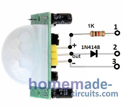
}Wiring and Pinout Details of PIR Human Presence Detector Module
In the following PIR module image, please remove the 1N4148 diode and connect the "out" pin directly with the relevant pin of the Arduino as described in the above explanation.
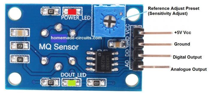
Wiring and Pinout Details of MQ135 Air Quality (VOC) Sensor
Please connect the analogue Output of the MQ135 sensor with the relevant pin of Arduino, as described in the above Arduino connection description.
Wiring and Pinout Details of DHT22 Humidity Sensor Module
Please connect the data "out" pin of the following DHT22 module with the relevant pin of Arduino, as previously described in the above sections.

Conclusions
So this code will keep checking all 3 PIRs, all 3 gas sensors and all 3 humidity sensors. If any one of them detects something, fan will start and timer will reset. If nothing is detected for 5 full minutes, then fan will stop. All 3 bathrooms are monitored together, so any one active will activate the fan.
This is how we can make full working smart automatic bathroom exhaust fan system using Arduino and multiple sensors.


Questions & Answers
Dear Sir,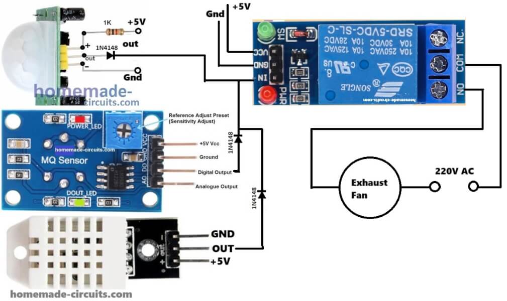 ”?
”?
Will this module “SUSWE-AC-DC 220v AC-DC Power Supply Module 5V 2A Switching Power Supply Board” will serve our purpose of 5VDC in “
In “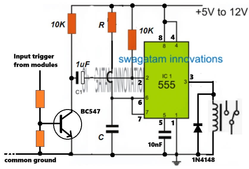 ” values and rating of 3 resistance and 1 capacitor is not shown, Please confirm. Is some standard reliable module is available for same application instead of making it?
Thanks.
Hi Manoj, yes the 5V module will work, in fact any regulated 5V DC power supply will work.
For the linked circuit, the values of the transistor base are 4.7k (upper resistor), 2.2k (lower resistor).
For the R and C values, you can calculate using the following software…
https://www.homemade-circuits.com/ic-555-timer-monostable-circuit-calculator-software/
Thanks.
This 5VDC supply will reduce one power point requirement at site and will look clean if accommodated in single casing, only one wire in and one wire out will give good aesthetic look.
For fan On-Off adjustment timer, please suggest some standard reliable module which is readily available for same application instead of making it? And where it will get fit or connect in the single fan circuit to control fan run duration?
Regards.
You are right, accommodating the power supply module will make the unit compact and clean.
For the timer module, please Google the phrase “5v delay timer module”, and you may get many good options.
Motion sensor with timer that starts at 10 minutes and stops at 20 minutes.
More simple than this — impossible!
And if someone wants a more complete version, then they can add a humidity sensor to block the fan from starting when not needed.
10 minutes is too long, it should within 20 seconds.
Very good for cleaning the environment before a new visit.
Installing a motion sensor (PIR), in my opinion, isn’t the best idea. When I set up a similar system to turn on lights in a dark room, I tried all kinds of sensors—microwave sensors, motion detectors, you name it. Unfortunately, they all require periodic movement inside the monitored area. What you really need isn’t a motion sensor but a presence detector! Those are pretty expensive, though. I solved the problem by replacing the motion sensor with an IR beam sensor—the system activates when the beam is crossed.
Honestly, it’s hard to imagine how a motion sensor would even work in a bathroom. Are you supposed to keep wiggling around while sitting on the toilet just to keep the lights on?
Thanks for your concern and comments. We have intentionally not considered lightings with this project as we needed time delay option for fan.
PIR sensors are actually extremely sensitive to human movements and stay latched for a few seconds once a movement is detected. Moreover these movements just needs to be within a span of 1 inch body movement, so i think while sitting in bathroom, moving within such a tiny range, and every 5 seconds, could be quite natural and normal ;). In fact sitting still, like statue, might sound unnatural and difficult. Using a beam sensor might not be accessible across the whole bathroom, and it requires an transmitter to be installed…so overall a PIR appears to be a better option according to me.
Honestly, I don’t think a motion sensor is even needed here. A humidity and temperature sensor is enough. Here’s how it works:
You walk into the bathroom—before you start showering, the humidity and temperature are way lower. Once you start, both go up, and that triggers the exhaust fan. The fan keeps running until humidity and temp drop back to normal levels.
After you’re done showering and leave, humidity and temp might still be high for a while. That’s why you only need those two sensors. What’s the point of a motion sensor here?
Well, now I feel the opposite, why use the humidity sensor and VOC sensor, why not just use only the PIR sensor with a delay ON and delay OFF features. Because if a person is using the bathroom for more than maybe 15 seconds then very likely he is doing some activity there, and in that case the exhaust fan needs to be switched ON, regardless of anything else. Cheap and effective.
Yes, that makes sense! Agreed 100%…
Thanks for your prompt response and sincere efforts,
Hope this will be useful for many.
You are most welcome. If you are not well versed with Arduino, you can try the following version without Arduino. Just hook up the relevant modules as shown in the diagram, and you are good to go. The diagram shows a single bathroom setup, for 3 bathrooms, you can just put those extra sensor modules in parallel with the indicated modules, through individual output diodes:

Can we add fan stop delay timer somehow in this version as was in Arduino?
The delay OFF function is already present in the PIR module which you can adjust according to your own specs…
First of all thanks for your prompt response. Up to what duration we can adjust, if VOC and Humidity sensor not activated to run fan? What if VOC and / or Humidity sensor activated to run the fan and PIR time limit is consumed but still VOC and / or Humidity sensor not deactivated due to inside situation to stop fan?
PIR will be continuously activated as long as a human is present inside the bathroom, and the PIR output will keep the relay ON for sometime, maybe 10 to 20 seconds even after the person has left the bathroom.
In case the other modules are activated without the presence of any human being then the delay off will not happen, and I think it may not be essential then, because delay off becomes essential only in the event when a human uses the bathroom…
However if you need a delay off for all the circumstances then you can add a 1000uF capacitor between the common cathodes of the shown diodes and ground…and increase the module’s relay resistor to maybe 22k…
How time will increase by including 1000uF capacitor and 22k resistor? As situation of VOC and Humidity is not going to solve in seconds, it may take 10-20 minutes to dry area and avoid mold situation. That is why we may require separate timer that will trigger delay after deactivation of PIR sensor but active VOC and / or Humidity sensor. Hope my requirement of separate delay timer is justified. Actually I am in process of making both the versions of your suggested concept and on the top of that I am not from this field so want to take care of things well in advance.
For longer delays you may have to employ a monostable as shown in the following image….just replace the existing relay module with the following delay relay module:

Thanks for providing alternate solution.
Maximum length of cables can be used for different sensors without losing signals strength (due to 3 locations)?
Rating of 5 VDC power supply? Will be needed separately for all sensor locations?
You are welcome!! I am not sure about the length of the cables that would not drop the 5V significantly. If it does then you may have to use 12V supply at the source, with 7805 ICs installed for the sensors in each of the bathrooms.
One power supply can be used at the source near the relay module (fan), either (12V 1 amp as described above, or 5V 1 amp, if it works), then this supply can be sent to the respective bathrooms through separate cables. Outputs from these modules can be similarly sent to the source (relay module) through separate cables.