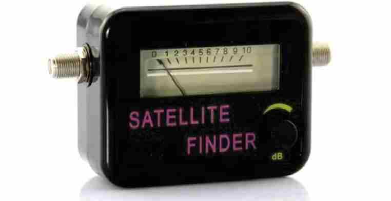
Here I have explained how to make a simple inexpensive satellite signal strength meter which can be used for aligning dish antennas with local satellites in order to achieve the correct positioning and maximum signal strength from the antenna.
How LNB Works
The LNBs that are used for receiving satellite signals (digital or analogue) are designed to grab the entire group of available transponders from the relevant satellite rather than single specific channels.
Due to the high gain features that modern LNBs possess today, the above procedure is likely to induce a whole lot of RF energy into the connected receiver while the dish antenna is optimally aligned.
The proposed signal meter circuit is configured for measuring the magnitude of RF signals over an extensive frequency range by averaging out the overall energy received from all the transponders at once.
It is not recommended to adjust your Meostat dish through this circuit since the power output from this dish could be too low for the meter to detect anything significant and might create confusions.
Image Credit: https://www.shop4fta.com/images/products/satellite-finder-signal-meter.jpg
Circuit Operation
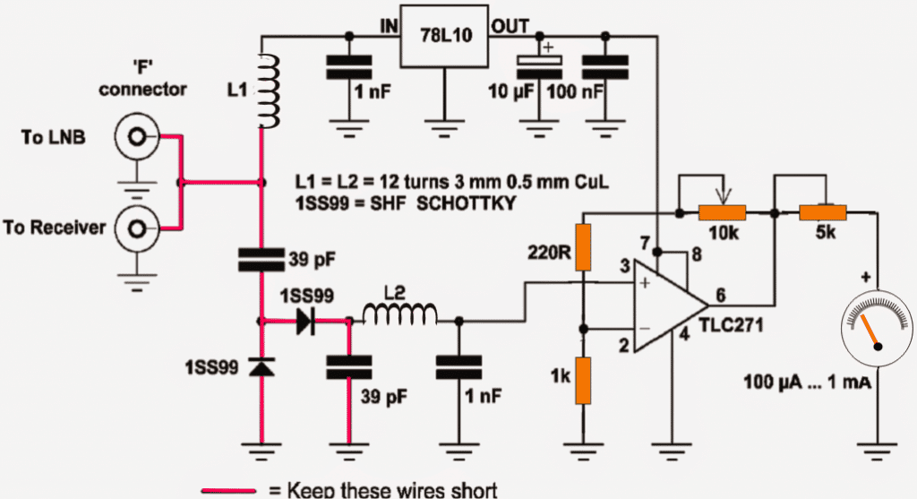
The circuit of the discussed satellite signal strength meter is very straightforward.The IC 78L10 converts the DC extracted from the LNB itself to 10V regulated output for powering the opamp amplifier used for sensing the RF signal strength.
L1 makes sure that the RF from the LNB is not leaked into the supply lines of the circuit in order to reduce signal loss and unnecessary interferences. The 39pF capacitors conversely allows the RF signal from the LNB to pass into the circuit but blocks the DC content from entering the input of the sensor stage.
The silicon fast recovery high speed diode network formed by the two 1SS99 Schottky diodes detect and rectify the acquired RF signals into recognizable DC. It is further filtered by the next 39pF capacitor in line.
L2 and the 1nF capacitors are positioned for filtering any unwanted infiltration that might sneak in along with the actual RF energy to be measured.
Finally the net RF signal is applied to the non-inverting pin of the opamp IC TLC271 which is configured as a high gain, high boost amplifier mode.
The feed back pots included in the opamp circuit are used for aligning and adjusting the gain of the signal meter so that the circuit may be tuned for producing maximum sensitivity and for detecting the minutest possible signal from the LNB.
Subsequently the detected and amplified RF signals is fed to a highly sensitive microammeter unit for translating the signal power into a readable visual output through corresponding needle deflections over the meter.
Circuit Diagram
How to Use the Satellite Signal meter Unit
It may be done by following these guideline steps: Detach the coaxial cable connected across your receiver unit and the LNB (at the LNB end), and simply integrate the signal meter’s input port to the LNB output socket through a small piece of coaxial cable.
After this it’s time to plug in the receiver cable which was disconnected from the LNB to the output port of the signal meter.
The ports provided with this homebuilt signal meter device actually does not have any particular orientation, as it can be witnessed that both the ports are configured in parallel, meaning any of the two ports may be used for the LNB and the receiver, anyway round.
Keep the receiver switched ON so that DC from the receiver is able to reach and power up the signal meter circuit as well as the LNB.
Now direct your dish position approximately toward the satellite zone in the sky, let your favourite tracking program get involved in the set up for determining the compass heading time at occasions when the sun attains identical direction (azimuth) with the satellite.
Optimizing the Control Pots
Next, grab the gain adjustment pot of the signal meter and carefully optimize the setting while you also align the azimuth elevation for getting as significant as possible a deflection on the meter.
Remember, even a variation of as low as a 5 degree from the dish could make the signal vanish instantly forcing you to start the procedure all over again, even worse you may simply tune the dish to receive some vague satellite transmission, therefore do it with great dexterity and with gentle hands.
Once the correct and the most optimal positioning of the dish is achieved, it may be fixed into position by tightening the clamps, After this, the placement of the LNB on the dish rod could also be optimized a bit for enhancing the effects.


Questions & Answers
Hi, I’m interested in building a signal strength meter for a DVB-T amplified log-periodic terrestrial antenna derived signal. The Sat finder circuit looks as if it should work as it does not appear to have a specific filter to only pass the Sat LNB output frequency band and therefore would probably work for the lower 450 -850 MHz frequency band of DVB-T? . Has anyone ever tried using it for this purpose? Are there any changes to component values you might suggest to compliment the lower frequency band? Any ideas very welcome.
Hello Swagatam,
Am interested in building dual bands (28GHz and 38GHz) transmitter and signal strength meter that will also display SNR. Could you please give an advice on this. Thanks
Hello Deeman, I am sorry I do not have sufficient data with me regarding the mentioned project.
hello where Can I buy it ?
Hello Sir, please give me complete part list about this circuit. you did not write about part list.
I am new and I want to try to make a circuit.
Thanks a lot for your help.
Latif
Latif, the parts are clearly indicated in the diagram, you just have to copy them and show the list to the shopkeeper…
Hi is it possible to substitute the IC TLC271 op-amp for any other op amp of the same class
Hi, any other might not work, basically it should be a very low noise type of opamp, you can check its datasheet to study regarding its specifications and then search for a similar one.
Simple and crisp explanation for a man who knows basic electronics.
Good.
Hi, do you have this Simulated Circuit in Multisim OR in some other simulation software?
If you have it, you can send it to my e-mail: pauloricardo.sts87@gmail.com
Help me, my friend.
I am sorry, I do not have it at the moment!!
Hello, what can i do with pin 1 and 5 of tlc271? Non-open?
keep them unused
Thank you for sharing your knowledge. Is it possible you add a "buzzer" in the output of Op Amp to also have an audible indication.
yes it is possible, but it will start sounding even at the weakest of the signal levels, or as soon as a signal is detected
I could not understand the meaning of L1 = L2 = 12 turns 3mm 0.5mm CuL
please tell me how to make this inductor or please suggest me the ready made inductor that I can use in this circuit.
both the inductors can be made by winding 12 turns over a 3mm plastic former using 0.5mm thick super enameled copper wire
So are you advising me to re-wind the transformer to 18v so that when i add the brigde rectifier and capacitor it will then reach 25.2v( ie 18 x 1.4)? Oq should i leave it at 25v that is producing 35v after bridge rectifier and capacitor(ie 25 x 1.4)?
both will work, make sure to mount the IC on a heatsink.
Ok sir. But sir, what is the difference between Operating supply voltage(18v) and DC supply voltage(28v)? And i saw somewhere on the net where they said that using a supply voltage greater than 18v will damage the Ic, that 12v transformer wil b ok so that afta rectification from the transformer, we now have 16.8v(ie 12 x 1.4). But using 25v transformer will yield 35v(ie 25 x 1.4) and the 35v has gone beyond the DC supply voltage which is 28v. I discovered that a 25v transformer, after the bridge rectifier with capacitor, will produce 35v. That's exactly what mine produced. My question is, where they wrong? Since the IC is for cars, and cars use 12v. Is the 35v from the bridge safe for the IC?
at 18v it'll just start operating correctly, at 28V optimally, while above this upto 50V it could require a big heatsink and will work with full potentials.
Ok. Maybe the Ic is bad. But sir, when i checked the datasheet, they said the Ic is 4 x 51w, but the one you referred to me is 4 x 45w. And again, they recommended driving the Ic with a supply voltage of 14.4v but they did'nt specify 25v in any where in the datasheet. Don't you think the 25v is harmful to the Ic? And at what safe voltage can i drive the Ic to provide 4 x 51w in a 4 ohms speakers or is it not possible?
see under "Absolute Maximum Ratings" in the datasheet….28V is the optimal operating V, while 50V is the peak value which must not be exceeded.
Please sir, there is a problem here. The schematics of TDA7560 is quite simple, yet it could'nt work out for me. I used the following components: R1=10k, R2=47k, C1 to C4=100nf (mylar capacitor), C5=0.47uf-50v(electrolytic capacitor), C6=47uf-50v(electrolytic capacitor), C7=6800uf-50v(electrolytic capacitor), C8=100nf (mylar capacitor), C9 to C10=1uf-50v(electrolytic capacitor). I believe mylar capacitors and polyesters are the same capacitors. I grounded the following pins: pin1, pin13, while i connected the following 4 pins together but did not ground them: "pin8, pin2, pin18, pin24" because when i grounded them, it resulted in short-circuiting the supply. I tried replacing the input capacitors with their electrolytic capacitor equivalent, yet no music output. I added a 20k pot in the input as the volume yet no result. I connected the center pin of the pot to one of the TDA7560's input and grounded one of the remaining two while the input went to the other one yet no music output. And the TDA7560 is heating up much though i used a very large heatsink. When i power it, it will be producing a little humming sound from the speaker to show that it is on but no music will be heard. And when i powered it ON and measured the supply voltage, it would read 18 to 19v, and the transformer is a 25v transformer. I grounded the mute and standby pins yet no sign, i also took them to Vcc, yet no sign. Please is there anything i did wrong? Please make out time to help me please, thanks
jideofor, pin8,2,18,24 all need to be grounded as per the datasheet diagram, if it shorting the power means either your IC is faulty or its connected incorrectly
i think you should make the PCB for the design and assemble the components on it for getting confirmed results.
You can find all the details along with the PCB layout info in the following link:
https://www.homemade-circuits.com/2012/08/exploring-ic-tda-7560-4-x-45w-quad.html
Sir, i have re-winded the 600VA transformer and it is now delivering 25v from 220v source. But i encountered two problems: 1) The transformer is producing sound. 2) The output current is greater than 20A. How can i correct these problems? Is the >20A current safe for the TDA7560? And why the noise?
As long as the voltage is within the specified limits of the IC, current won't be a problem.
at 25V, higher input amps won't have any affect.
Ok. I went to buy 25v transformer, and the one they gave me has no current rating and i am not sure it is 25v, 10amp transformer. So, in order to prevent mistakes, i have a 600VA transformer i got from a UPS, and it is a center tapped transformer. My question is, can i use it for the IC TDA7560? And it is not upto 25v, i guess it should be around 7.5v-0v-7.5v according to what is labelled on it. But i know the current is more than enough. Please sir, will it work if i use the two wires excluding the center one?
7.5+7.5 = 15V will produce quite a low output, not worth using…it's better you try the other one that you bought from the market rated 25V.
Thanks! Secondly, is the transformer a center-tapped or not? I mean, is the IC dual voltage rail? Can i power it with 0v – 25v transformer 10amp?
It will require a single rail power supply, not center tapped. 0-25V will do
Please sir, from the datasheet of TDA7560, i discovered that it is a car radio amplifier IC. My question is, can i use it to produce an audio amplifier i will use at home? Or must it b for cars only? And what is the recommended transformer's voltage and current? Is it CenterTapped Transformer or single? Finally, which of these will you recommend depending on their sound quality? TDA7560 and TDA7386. Please help me with all these questions. Thanks!
..both the ICs are good
It can be used anywhere as long the voltage/current specs are correctly applied to the IC.
operate it at 25V DC/10amps