• Skip to main content
  • Skip to primary sidebar

Homemade Circuit Projects

Need circuit help? Post them in the comments! I've answered over 50,000!

Blog | Categories | About | Hire Me | Contact | Calculators-online
You are here: Home / Audio and Amplifier Projects / Public Address (PA) Amplifier Circuit

Public Address (PA) Amplifier Circuit

Last Updated on May 15, 2026 by Swagatam 4 Comments

A public address system (PA system) is an electronic system that includes a set of audio electronic devices such as microphones, amplifiers, loudspeakers, and other similar audio equipment. It is designed to boost the volume of a human speech, or a musical source, or some other audible sound input to an amplified version through an attached loudspeaker.
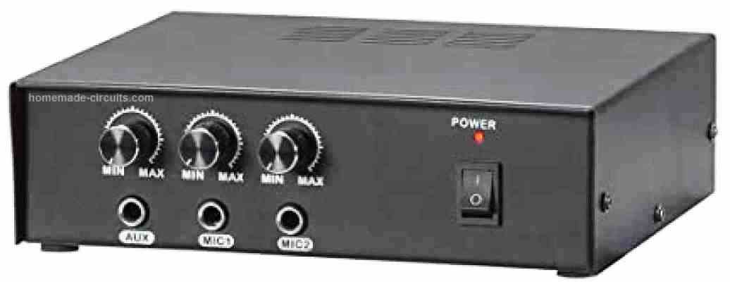
Table of Contents
  • How the Circuits Works

PA systems are normally employed in different public areas that calls for an human speaker, artist, etc. to be loudly audible over a substantial distance so that the speech of the person using the PA system becomes audible to a large gathering or crowd. Common places where a PA system can be used are sports stadiums, public vehicles, and live rock and music venues, and occasions.

A PA system can consist of several microphones or additional audio sources, an audio mixer unit which are able to blend and customize the audio signals coming from the various sources, and amplifiers. The output is subsequently fed to a loudspeaker for getting an amplified volume, resulting in a wider distribution of the sound.

How the Circuits Works
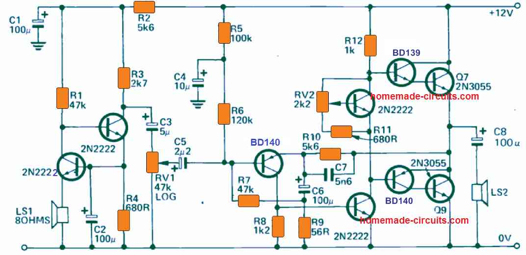
The proposed public address circuit I have explained in this article works with a small speaker, whose impedance is unimportant. This speaker is hooked up across the emitter of Q1.

The above tiny speaker is used like a microphone, where the user needs to speak for getting his voice amplified.

Q1 is configured in the common base format which causes an extremely increased signal to be generated and fed across its collector.

Transistor Q2, is wired up in the common emitter configuration. Q2 is used for increasing the amplification further. The audio or the speech signal from the collector of Q2 is applied by means of the C3 which acts like a blocking capacitor to VR1, configured like a volume control.

The general de-stabilisation is achieved by having the base biasing of Q1 through the emitter of Q2.

The design of this public address power amplifier circuit is reasonably standard and is configured using a robust looking output stage.

This strong output stage is employed so that the amplifier is able to drive a couple of large P.A. type horns in parallel.

With these types of load at the output we can expect an output power of 8W over the horns or the speakers.

Because the public address or PA amplifier circuit is supposed to be used for amplifying mostly the human speech, a wide bandwidth specification is not important.

Therefore, the capacitor C7 is included to roll off any frequency response that may appear over the 5kHz range. The capacitor C6 is additionally employed for delivering a fast roll off around the bass frequency region.

Power transistors Q7 and Q9 must be installed with a 5" x 4" finned type heatsink. Make sure the body of the transistor Q4 remains thermally in contact with the heatsink.

You'll also like:

  • home theater1 1How to Make an Outstanding Home Theater System
  • simplest 10 watt amplifier circuitSimple 10 Watt Amplifier Circuits using Transistors
  • speaker schemPlaying a Melody Using Arduino
  • 1002Bwatt2Bmosfet2Bamplifier2BcircuitDIY 100 Watt MOSFET Amplifier Circuit with PCB

Filed Under: Audio and Amplifier Projects Tagged With: Address, Amplifier, PA, Public

About Swagatam

I am an electronics engineer and doing practical hands-on work from more than 15 years now. Building real circuits, testing them and also making PCB layouts by myself. I really love doing all these things like inventing something new, designing electronics and also helping other people like hobby guys who want to make their own cool circuits at home.

And that is the main reason why I started this website homemade-circuits.com, to share different types of circuit ideas..

If you are having any kind of doubt or question related to circuits then just write down your question in the comment box below, I am like always checking, so I guarantee I will reply you for sure!

Previous Post: « Bench Amplifier Circuit
Next Post: IC 741 Power Supply Circuits »

Reader Interactions

Questions & Answers

Total Posts: 4
Newest Oldest
Abisai omoke
January 22, 2025 • 2 years ago #168080

Why output transistors get hot when my amplifier is on

Reply
SwagatamAdmin
January 23, 2025 • 2 years ago #168086

Did you adjust the RV2 correctly?

Reply
Eric Bundi
July 20, 2021 • 5 years ago #92647

How can I have a HiFi loud music using LM 386 IC

Reply
SwagatamAdmin
July 20, 2021 • 5 years ago #92650

you may have to use power transistors at the output of the IC for boosting the output

Reply

Need Help? Please Leave a Comment! We value your input—Kindly keep it relevant to the above topic! Cancel reply

Your email address will not be published. Required fields are marked *

Primary Sidebar

My YouTube Channel

Circuit Simulator: Draw and Simulate Schematics

circuit simulator image

Categories

  • Arduino Projects (95)
  • Audio and Amplifier Projects (134)
  • Automation Projects (18)
  • Automobile Electronics (104)
  • Battery Charger Circuits (90)
  • Datasheets and Components (109)
  • Electronics Theory (151)
  • Energy from Magnets and Earth (43)
  • Games and Sports Projects (11)
  • Grid and 3-Phase (20)
  • Health related Projects (27)
  • Home Electrical Circuits (13)
  • Indicator Circuits (16)
  • Inverter Circuits (98)
  • Lamps and Lights (161)
  • Meters and Testers (72)
  • Mini Projects (28)
  • Motor Controller (68)
  • Oscillator Circuits (30)
  • Pets and Pests (15)
  • Power Supply Circuits (91)
  • Remote Control Circuits (50)
  • Security and Alarm (65)
  • Sensors and Detectors (107)
  • SMPS and Converters (46)
  • Solar Controller Circuits (62)
  • Temperature Controllers (44)
  • Timer and Delay Relay (51)
  • Voltage Control and Protection (44)
  • Water Controller (37)
  • Wireless Circuits (31)

Subscribe to get New Circuits in your Email

Other Links

  • Privacy Policy
  • Cookie Policy
  • Disclaimer
  • Copyright
  • Videos
  • Sitemap

People also Search

555 Circuits | 741 Circuits | LM324 Circuits | LM338 Circuits | 4017 Circuits | Ultrasonic Projects | SMPS Projects | Christmas Projects | MOSFETs | Radio Circuits | Laser Circuits | PIR Projects |

Recent Comments

  • Nicodemus Onate on How to Design Your Own Inverter Transformer
  • Swagatam on Making a Self-Powered Generator
  • Swagatam on Electronic Circuit Projects, Tutorials, and Practical Engineering Solutions
  • Ranjith Gurusinghe on Making a Self-Powered Generator
  • Mazlom on Electronic Circuit Projects, Tutorials, and Practical Engineering Solutions

Social Profiles

  • Twitter
  • YouTube
  • Instagram
  • Pinterest
  • My Facebook-Page
  • Stack Exchange
  • Linkedin

Calculators

  • ZVS Induction Heater + Tank Calculator Tool
  • Zener Diode Calculator
  • Wire Current and Thickness Calculator (Ampacity Calculator)
  • Voltage Divider Calculator
  • Transistor Base Resistor Calculator
  • Transistor Astable Multivibrator Calculator
  • TL431 Calculator
  • Solar Panel, Inverter, Battery Calculator
  • Ferrite Core Air Gap Calculator Tool
  • Parallel MOSFET Calculator Tool: How to Connect MOSFETs in Parallel Safely
  • LC Resonance Calculator for EV Battery Charger Circuits
  • LED String Series Resistor Calculator
  • PFC (Power Factor Correction) Calculator Tool: 3kW
  • Passive Power Factor Correction (PFC) Calculator
  • LM567 IC Calculator Tool
  • SMPS Flyback Boost Converter Calculator
  • Shunt Resistor Calculator for Ammeters
  • SCR and Triac Gate Resistor Calculator
  • Battery Back up Time Calculator
  • Boost Converter Calculator (Non-Isolated)
  • Bootstrap Capacitor Calculator
  • Buck Converter Calculator
  • Buck-Boost Converter Calculator
  • Capacitance Reactance Calculator
  • DCM Flyback Transformer & Wire Gauge Wire Size Calculator Tool
  • Filter Capacitor Calculator
  • IC 4047 Calculator (Frequency and PWM)
  • IC 4060 Calculator
  • IC 555 Astable Calculator
  • IC 555 Monostable Calculator
  • IC SG3525, SG3524 Calculator
  • Inductance Calculator
  • Induction Heater Inductor and Resonant Frequency Calculator
  • Induction Heater Work Coil Calculator
  • Inverter LC Filter Calculator
  • LC Resonance Calculator
  • LED Current Calculator
  • LM317, LM338, LM396 Calculator
  • NAND/NOT Gate RC Values Calculator
  • NOT, NAND Gate Frequency Calculator
  • Notch Filter Calculator Tool
  • Ohm’s Law Calculator
  • Phase Angle Phase Shift Calculator
  • Power Factor (PF) Calculator
  • RC Filter Calculator
  • Reactance Calculator
  • Sine Table Calculator for SPWM Arduino Code
  • Small Signal Transistor(BJT) and Diode Quick Datasheet
  • SMPS Calculator for Toroidal Ferrite Transformers
  • SMPS Flyback Transformer Calculator – Design by Target Duty Cycle
  • TL431 Calculator
  • Op-Amp Hysteresis Resistor Calculator

© 2026 · Swagatam Innovations