• Skip to main content
  • Skip to primary sidebar

Homemade Circuit Projects

Need circuit help? Post them in the comments! I've answered over 50,000!

Blog | Categories | About | Hire Me | Contact | Calculators-online
You are here: Home / Home Electrical Circuits / 2 Simple Washing Machine Circuits Explained

2 Simple Washing Machine Circuits Explained

Last Updated on June 30, 2026 by Swagatam 9 Comments

In this post I have explained how to make a couple of simple washing machines using a bidirectional single motor with timer and a simple version using cam shaft mechanism, cheaply.

Table of Contents
  • Audio/Video Representation
  • Circuit Working
  • Using Only Motor and Cam Shaft Mechanism (No Circuit)
  • A Simple Washing Machine Mechanism
    • Simulating the Washing Machine Operation

In the first design we use a bidirectional, alternately rotating clockwise and counter clockwise with a pause in the middle:

Audio/Video Representation

Circuit Working

The IC 555 here is working like the clock generator and its timing can be adjusted through the 100k preset and the 22uF capacitor. So by adjusting this preset the motor forward/reverse timing can be increased or decreased.
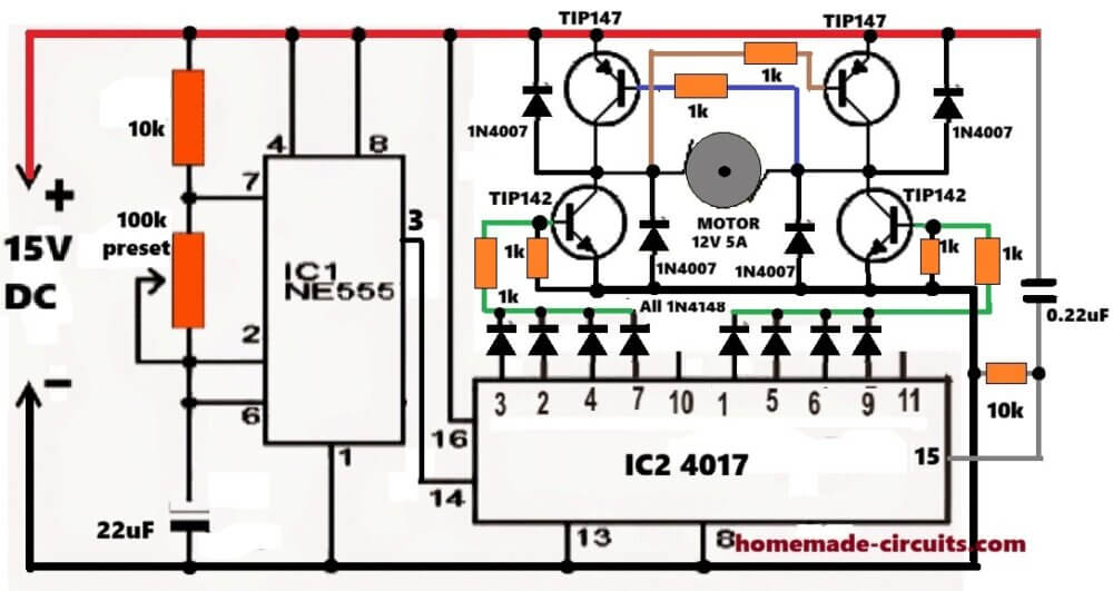
The clock pulses from pin#3 of the 555 goes to pin#14 of the IC 4017, and the 4017 then shifts its outputs one by one.

Here the IC 4017 pin 3, 2, 4, 7 outputs are combined through the diodes to switch one diagonal side of the H-bridge, so the motor rotates in one direction for four counts.

After this, pin 10 is not connected anywhere intentionally, so during this count all the transistors remain OFF and the motor gets a small pause before reversing. This helps to reduce sudden reverse current stress.

Next pin 1, 5, 6, 9 outputs of the 4017 become high, and these are combined to drive the opposite diagonal pair of the H-bridge transistors, causing the motor to rotate in the opposite direction.

Again pin 11 is left unused, so another small pause is created before the cycle repeats.

The ground connection of pin#15 via the 10k resistor resets the IC 4017 so the sequence starts again from pin#3.

So the sequence becomes:

Forward Rotation then Pause, Reverse Rotation then Pause, then again repeat, this goes on continuously.

The TIP142/TIP147 transistors are forming the H-bridge motor driver stage. The 1N4007 diodes are for absorbing the motor back EMF spikes during switching.

Overall the idea looks OK for a small DIY washing machine agitator type application. Proper heatsinks on the TIP142/TIP147 will be important if the motor current is high.

Using Only Motor and Cam Shaft Mechanism (No Circuit)

Washing machines are costly devices which may not be affordable for a section of the population and also to villagers who even might not have an easy access to these equipment. A homemade version for the same may be learned in this article.
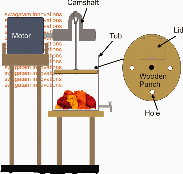
Simple cloth washer system using Camshaft Motor Push Pull


A Simple Washing Machine Mechanism

A rather straightforward approach may be witnessed in the above shown homemade washing machine mechanism, where a motor/camshaft mechanism is used for implementing a slow punching or hammering action over the clothes which needs to be cleaned and washed.

The motor spindle can be seen attached with a camshaft and a vertical rod with a wooden punch.

The wooden punch is supposed to be fixed inside a plastic tub such that the punch diameter is just smaller than the tub inner diameter. This allows the punch to execute the hammering action smoothly within the specified range.

In order to facilitate an easy introduction of the clothes, the wooden punch has a lid cut-out over its surface, which operates with a hinge and lock.

The clothes are pushed at the bottom of the tub by opening this lid upwards and then inserting the clothes through the opening towards the bottom of the tub.

Next, the required amount of water and detergent is poured through this lid over the clothes.

Once this is done, the lid is closed and locked.

Finally, the motor is switched ON so that the slow punching action is initiated over the clothes.

The wooden punch can be seen having a bunch of holes drilled across it, this allows water to squeeze in and out while the hammering action is being carried out. The action ensures a better cleansing due to an active exchange and churning of water/detergent over the clothes.

Note: The motor should be integrated with a built-in gear box in order to carry out a relatively slow and gentle rotation (hammering) action over the clothes.

Simulating the Washing Machine Operation

A Rough Simulation to understand how to make a simple washing machine and its mechanism.

 

Simple Washing Machine GIF Simulation

You'll also like:

  • BLDCBLDC Ceiling Fan Circuit for Power Saving
  • Single Phase Variable Frequency Drive VFD Circuit
  • 50V BLDC motor controller using L6235 IC module50V 3-Phase BLDC Motor Driver
  • incubatortimerreverseforwardmotorIncubator Reverse Forward Motor Controller Circuit

Filed Under: Home Electrical Circuits, Motor Controller Tagged With: Machine, Simple, System, Washing

About Swagatam

I am an electronics engineer and doing practical hands-on work from more than 15 years now. Building real circuits, testing them and also making PCB layouts by myself. I really love doing all these things like inventing something new, designing electronics and also helping other people like hobby guys who want to make their own cool circuits at home.

And that is the main reason why I started this website homemade-circuits.com, to share different types of circuit ideas..

If you are having any kind of doubt or question related to circuits then just write down your question in the comment box below, I am like always checking, so I guarantee I will reply you for sure!

Previous Post: « Borewell Motor Pump Starter Controller Circuit
Next Post: How to Connect a TSOP1738 IR Sensor »

Reader Interactions

Questions & Answers

Total Posts: 9
Newest Oldest
Anirudh Kundu
August 10, 2016 • 10 years ago #43455

Hello sir,

I recently changed the dryer motor of my samsung washing machine. But what i noticed is after i wired the motor exactly as the wiring color code, the motor spins in the opposite direction to what is was earlier.

Can you please help me as how can i reverse the direction of the motor?
The motor is a single phase, 3 wire motor. Has a 6 Mfd capacitor.

Thanks

Reply
SwagatamAdmin
August 10, 2016 • 10 years ago #43465

Hello Anirudh, sorry I have no idea about it since the problem could be specifically due to an incorrect wiring, you can consult your local washing machine technician or the customer care

Reply
manjunath
September 24, 2015 • 11 years ago #34310

sir, as this washing mechin mentioned simple. can this mechin rotate with help of bicycle . instead of electric motor . this would be more simple and much usefull to villegers.
thank you

Reply
SwagatamAdmin
September 25, 2015 • 11 years ago #34320

Manjunath, yes the motor can be replaced with a bicycle mechanism…however the motor option looks more convenient and effective, because a bicycle will need a manual effort which might add to the troubles the villagers…electricity is now available even in the villages or a solar energy option could be tried

Reply
Abu-Hafss
September 23, 2015 • 11 years ago #34270

Dear Swagatam

Although you have already mentioned SIMPLE, it would be more effective if you introduce some technique to tumble the clothes when the punch is lifted up.

Reply
SwagatamAdmin
September 23, 2015 • 11 years ago #34277

Dear Abu-Hafss,

adding any kind of improvement could make it complex….so let's keep it as given, and may be let the user decide what else he may want and be able to add in the design…

Reply
Mark
August 30, 2019 • 7 years ago #69778

Sir swagatam good day. Can you give me a circuit how to reduce the current bill in my home? Please I badly needed

Reply
SwagatamAdmin
August 30, 2019 • 7 years ago #69782

Hi Mark, That’s illegal, so I can’t help in this regard.

Reply
Mark
August 31, 2019 • 7 years ago #69801

Ok mr swagatam. Thank you ????

Reply

Need Help? Please Leave a Comment! We value your input—Kindly keep it relevant to the above topic! Cancel reply

Your email address will not be published. Required fields are marked *

Primary Sidebar

My YouTube Channel

Circuit Simulator: Draw and Simulate Schematics

circuit simulator image

Categories

  • Arduino Projects (95)
  • Audio and Amplifier Projects (134)
  • Automation Projects (18)
  • Automobile Electronics (104)
  • Battery Charger Circuits (90)
  • Datasheets and Components (109)
  • Electronics Theory (151)
  • Energy from Magnets and Earth (43)
  • Games and Sports Projects (11)
  • Grid and 3-Phase (20)
  • Health related Projects (27)
  • Home Electrical Circuits (13)
  • Indicator Circuits (16)
  • Inverter Circuits (98)
  • Lamps and Lights (161)
  • Meters and Testers (72)
  • Mini Projects (28)
  • Motor Controller (68)
  • Oscillator Circuits (30)
  • Pets and Pests (15)
  • Power Supply Circuits (91)
  • Remote Control Circuits (50)
  • Security and Alarm (65)
  • Sensors and Detectors (107)
  • SMPS and Converters (46)
  • Solar Controller Circuits (62)
  • Temperature Controllers (44)
  • Timer and Delay Relay (51)
  • Voltage Control and Protection (44)
  • Water Controller (37)
  • Wireless Circuits (31)

Subscribe to get New Circuits in your Email

Other Links

  • Privacy Policy
  • Cookie Policy
  • Disclaimer
  • Copyright
  • Videos
  • Sitemap

People also Search

555 Circuits | 741 Circuits | LM324 Circuits | LM338 Circuits | 4017 Circuits | Ultrasonic Projects | SMPS Projects | Christmas Projects | MOSFETs | Radio Circuits | Laser Circuits | PIR Projects |

Recent Comments

  • Martins Vita on Understanding IC 4043B, IC 4044B CMOS Quad 3-State R/S Latch – Working and Pinouts
  • Swagatam on Inverter Circuit with Feedback Control
  • Jerry Adeosun on Inverter Circuit with Feedback Control
  • Swagatam on Adjustable Voltage Regulator Circuit using LM324 IC with Over Current Protection
  • David on Adjustable Voltage Regulator Circuit using LM324 IC with Over Current Protection

Social Profiles

  • Twitter
  • YouTube
  • Instagram
  • Pinterest
  • My Facebook-Page
  • Stack Exchange
  • Linkedin

Calculators

  • ZVS Induction Heater + Tank Calculator Tool
  • Zener Diode Calculator
  • Wire Current and Thickness Calculator (Ampacity Calculator)
  • Voltage Divider Calculator
  • Transistor Base Resistor Calculator
  • Transistor Astable Multivibrator Calculator
  • TL431 Calculator
  • Solar Panel, Inverter, Battery Calculator
  • Ferrite Core Air Gap Calculator Tool
  • Parallel MOSFET Calculator Tool: How to Connect MOSFETs in Parallel Safely
  • LC Resonance Calculator for EV Battery Charger Circuits
  • LED String Series Resistor Calculator
  • PFC (Power Factor Correction) Calculator Tool: 3kW
  • Passive Power Factor Correction (PFC) Calculator
  • LM567 IC Calculator Tool
  • SMPS Flyback Boost Converter Calculator
  • Shunt Resistor Calculator for Ammeters
  • SCR and Triac Gate Resistor Calculator
  • Battery Back up Time Calculator
  • Boost Converter Calculator (Non-Isolated)
  • Bootstrap Capacitor Calculator
  • Buck Converter Calculator
  • Buck-Boost Converter Calculator
  • Capacitance Reactance Calculator
  • DCM Flyback Transformer & Wire Gauge Wire Size Calculator Tool
  • Filter Capacitor Calculator
  • IC 4047 Calculator (Frequency and PWM)
  • IC 4060 Calculator
  • IC 555 Astable Calculator
  • IC 555 Monostable Calculator
  • IC SG3525, SG3524 Calculator
  • Inductance Calculator
  • Induction Heater Inductor and Resonant Frequency Calculator
  • Induction Heater Work Coil Calculator
  • Inverter LC Filter Calculator
  • LC Resonance Calculator
  • LED Current Calculator
  • LM317, LM338, LM396 Calculator
  • NAND/NOT Gate RC Values Calculator
  • NOT, NAND Gate Frequency Calculator
  • Notch Filter Calculator Tool
  • Ohm’s Law Calculator
  • Phase Angle Phase Shift Calculator
  • Power Factor (PF) Calculator
  • RC Filter Calculator
  • Reactance Calculator
  • Sine Table Calculator for SPWM Arduino Code
  • Small Signal Transistor(BJT) and Diode Quick Datasheet
  • SMPS Calculator for Toroidal Ferrite Transformers
  • SMPS Flyback Transformer Calculator – Design by Target Duty Cycle
  • TL431 Calculator
  • Op-Amp Hysteresis Resistor Calculator

© 2026 · Swagatam Innovations