TSOP17XX series devices are advanced infrared sensors having a specified center frequency of operation which makes their detection extremely reliable and foolproof.
In this post I have explained how to connect a TSOP series infrared sensor and use it for a specified IR remote control operations.
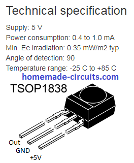
TSOP IR Sensor Specifications
A TSOP series of IR sensor ICs may consist many variants which differ marginally from each other, these may be in the form of TSOP22.., TSOP24.., TSOP48.., TSOP44..
However the most popular and most commonly used is the TSOP1738 IC module which is from the TSOP17XX series.
The other variants from this group are available with the following numbers:
TSOP1733, TSOP1736, TSOP1737, TSOP1740, TSOP1756, TSOP1738CB1, TSOP1738GL1, TSOP1738KA1, TSOP1738KD1, TSOP1738KS1, TSOP1738RF1, TSOP1738SA1, TSOP1738SB1, TSOP1738SE1, TSOP1738SF1, TSOP1738TB1, TSOP1738UU1, TSOP1738WI1, TSOP1738XG1, TSOP1740, TSOP1740CB1, TSOP1740GL1, TSOP1740KA1, TSOP1740KD1, TSOP1740KS1, TSOP1740RF1.
All the above TSOP variants have identical features and characteristics except their center working frequency, which may typically range between 30 kHz to 60 khZ.
How the Connect TSOP1738 sensors
Connecting or wiring a TSOP1738 infrared sensor is actually very easy, once you know how it responds to supply voltage and the IR signals applied across its specified pinouts.
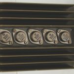
The diagram below shows the a standard TSOP infrared sensor IC, whose pinouts can eb seen marked as (-), (+) and the OUT.
The (+) and the (-) are the supply pins of the IC and are specified to be connected across a 5V typical supply level, to be precise any voltage between 3 and 6V may be aplied here, although 5V works the best, and is recommended since it can be easily tailored using a 5V regulator IC 7805 and allows a wide range of input to be used (between 6V and 24V).
The curved lens which can be seen over the central portion of sensor body is where the infrared signal from a remote control handset is focused for enabling the TSOP to initiate its sensing operations.
TSOP1738 Sensor and IC 7805 Pinout Details
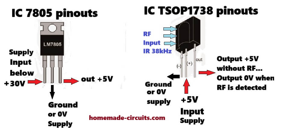
NOTE: The pinout polarity is different for the TSOP1838 IR detector, as shown below. So please verify the pinout sequence if you are using a different variant of the IC.
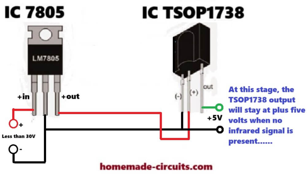
How connect Supply Voltage to TSOP1738
The following image shows how the TSOP1738 IC needs to be wired and connected across a +5V supply voltage and how its output may respond in the presence and absence of a 38kHz IR (infrared) signal input...
How TSOP1738 Responds to Infrared Signal
I have explained step wise how a wired TSOP1738 sensor behaves or responds when an IR signal is focused towards its lens.
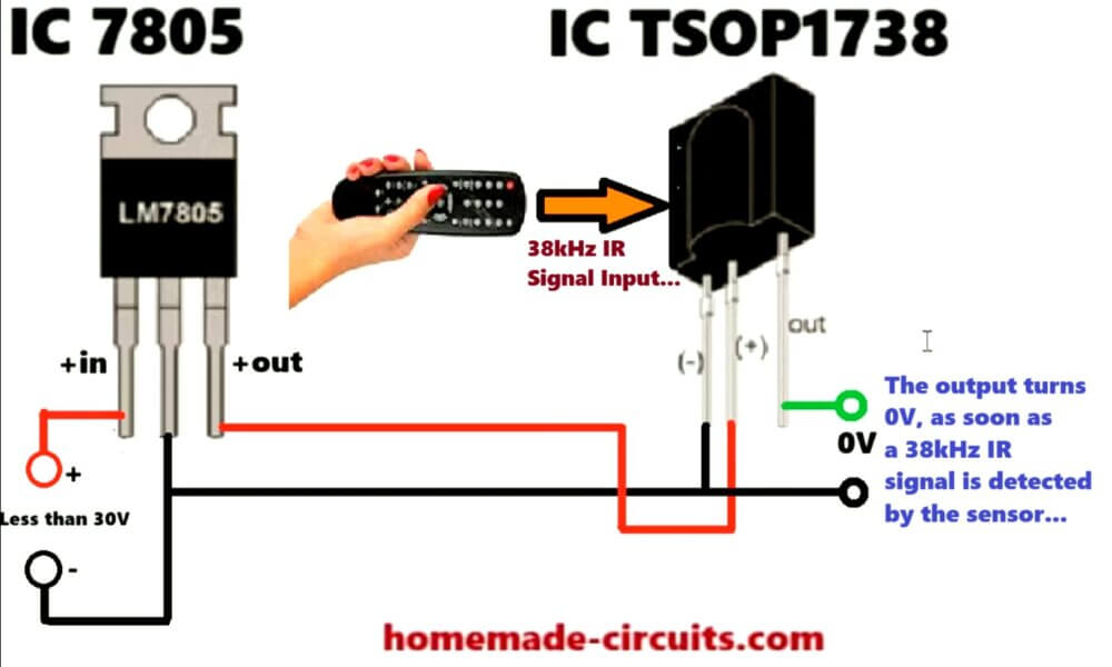
The TSOP1738 IC output stays at high +5V as long as there's no 38kHz IR signal being applied to its sensor lens surface. However as soon as a 38kHz IR signal is detected on its sensing lens surface, its output quickly turn into a 0V output.
Video Clip
Initially the Output is a +5V (Supply Level)
As soon as the TSOP is applied with a supply voltage (via a 5V regulator), it responds by making its output pin high or at the positive (+5V) level.
This level is maintained, as long as an input infrared signal is not pointed or is focused towards the lens of the TSOP
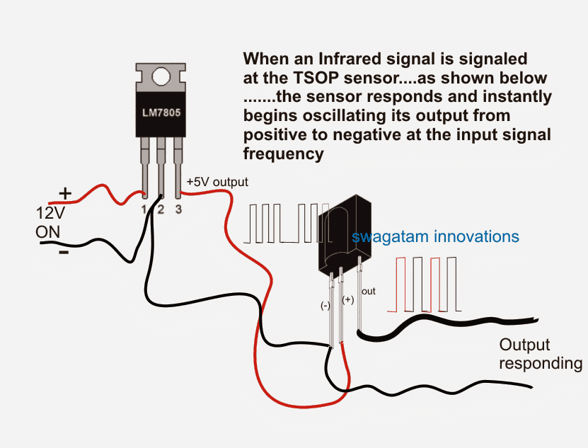
When an IR Signal is Applied
In the above diagram we can see IR signal frequency being applied and approaching the lens of the TSOP, until it touches the lens of the sensor.
The moment the IR signal reaches the lens of the TSOP, the output of the TSOP begins responding and oscillating in tandem with the focused infrared signal.
Remember, the input IR frequency focused towards the TSOP sensor must be oscillated at a 38 KHz frequency, otherwise the TSOP sensor will not respond. This frequency may be slightly different for the different variants of the TSOP sensors.
The Output Waveform of the Sensor
The output waveform indicates how the output of the IC oscillates between a positive (initial status) and negative (sensing status) across its "OUT" pins in an alternating pattern, as long as the input IR is kept focused towards it.
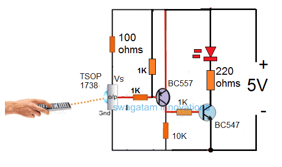
How to configure the above response from the TSOP1738 sensor for driving a relay stage.
A classic example may be seen in the following diagram taken from the article "remote controlled fish feeder", where we can see the TSOP being used for an IR remote control application and for a toggling action in response to an IR input triggering signal.
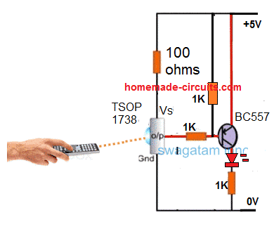
Basic Connection Details of TSOP1738 in a Circuit
Simplified Design
Application Schematic for TSOP1738 Relay Operation
Parts List
- R1, R3 = 100 ohms
- R4, R2 = 10K
- T1 = BC557
- T2 = BC547
- Relay 12V, 400 ohms
- IC = 7805
- D1 = 1N4007
- Sensor = TSOP17XX
- C1, C2 = 22uF/25V
Here we can see that a PNP transistor is being used for toggling the relay, I have explained why exactly a PNP device is required for toggling a TSOP sensor, why an NPN BJT may not be suitable for the same.
Through the above explanation we understood the fact that while the TSOP is in the standby mode or as long as there's no IR signal focused, the output from the device holds a positive potential.
This implies that if an NPN was used in conjunction with this output then this would force the transistor to remain switched ON in the standby mode, and switch it OFF in the presence of an IR signal....
This is technically incorrect because this would keep the relay switched ON all the time and switched OFF only while an IR signal was triggered...this condition is not recommended and therefore we use a PNP transistor which inverts the response from the TSOP sensor and toggle the relay ON only in response to an IR signal, and keeps the relay switched OFF normally while the sensor is in the standby mode (no IR signal).
Here C2 is used to filter the ripples or the pulsating DC output of the TSOP, so that the transistors activate properly and without causing a chattering effect on the relay

Questions & Answers
hello I’ne need the complete assembly of’un flame detection by flame probe’ionization by clicking the relay in contact with the flame on the probe and closing it in the’ absence of the flame .
I think you can try the circuit presented in the following article:
https://www.homemade-circuits.com/temperature-controlled-relay-switch-circuit/
Can I have a digital controlled timer circuit along with software.
Sorry, don’t have it right now with me.
Zelo lepo opisano,hvala.Lp Stanko
Thank you Stanko!
Hi Swagatham
Thanks so much for all your replies I got the on the other posts
Kind regards
Val
No problem Val, all the best to you!
Hi Swagatham
Thank You for your reply
I did try out the circuit with TSOP 1738 (Receiver) & the 555 IC Transmitter and I used a 330ohm resistor for the 940nm 5mm transmitter and I’m getting a range of 12 feet
I also used tubular enclosures for both transmitter & Receiver is it possible to increase the range by using magnifier glass to improve the beam, May be I sound crazy but I’ve seen this being used in our garage door opener , the sensors are at the bottom guide rail, so when the door is coming down if someone by mistake tries to enter it immediately triggers and reverses the door back up
Thanks for all the help & support
All the best to you
That’s great Val, I am glad you cold achieve the range of 12 feet distance using TSOP1738 sensor.
Using a magnifying glass sounds a bit strange, but who knows it might just work, because after all the IR waves are also light waves and could be concentrated using magnifying lens, it is worth trying.
Hi Swagatham
Tried out the circuit with the TSOP 1738 and the transmitter using an old TV REMOTE & with a Transmitter using the 555 IC circuit (second one) which I sent you earlier by email
Both work good, but for continuous monitoring the 555 IC is better and the max range I get is 8 feet from transmitter to receiver with a 270 ohm resistor in series with the transmitter IR LED . Is it possible to increase the range to 12 feet or more
Thanks Swagatham
Hi Val,
Glad you could make the circuit work.
12 feet range should be easily available with a little adjustment in the alignment, according to me. You can use 9V or 12V for the transmitter to increase its power. You can fine tune the 38kHz frequency at the 12 feet distance and check if that helps to increase the reception quality.
Hi Swagatham
I ve seen the circuit which is on the link you sent for the transmitter to trigger the TSOO 1738 receiver circuit right
What is the voltage to be used and how do I connect the IR LED Transmitter to the 555 circuit at pin 3. Can you please send me the complete circuit diagram
Thanks Swagatham for your time
All the best to you
Val
Hi Swagatham
Thanks for your reply shall try out the circuit and let you know how it works
All the best to you
No problem Val, wish you all the best!
Hi Val,
The voltage can be anything between 5V and 12V. You can connect the photodiode to pin#3 through a 330 ohm or 470 ohm resistor. The longer lead of the LED will connect with the pin#3 and shorter lead with the ground line. The resistor can be in series with any one of the leads of the LED
Hi Swagatham
With 5 volts the range and sensitivity is not good it is better with the 12 volt supply and a 270 ohm resistor in series with the transmitter
Is this ok by you .
The range I get is max 8 feet with the IR led transmitter from Amazon Gikfun 5mm 940nm
Is it possible to increase the range , I tried with various pots between pin 8 & 7 no difference
Please reply, thanks Swagatham
Hi Val,
Yes 12V and the 270 ohms looks OK to me.
If you are using the IR photo LEDs the range will be less and restricted, to increase the range you must replace the receiver diode with TSOP1738 and use the transmitter with 38 kHz frequency
Hi Swagatham
In this blog The first circuit with BC547 is almost the same I have and further below you have a circuit which activates a relay this is what I wanted and shall try it out
My question is instead of using a regular remote to activate the relay can you suggest a circuit with a transmitter which keeps the relay normally off and is activated ON when the transmitter signal is interrupted
Thanks
Hi Val,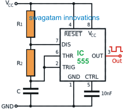
a TSOP sensor will activate when a 38kHz signal is focused on it. You can build a 555 astable oscillator with 38kHz frequency and that will do the job for you.
You can use the following circuit:
R2 can be a 100K resistor, R1 can be a 10K resistor, and C can be a 0.1uF capacitor. You will have to connect a 1M pot or a 100K pot might also work, in series with R1 and then you can use this pot to adjust the output frequency of the 555 astable. Pin#3 can be used for connecting the IR transmitter photodiode.
By keeping the transmitter focused on the receiver you can keep adjusting the pot until you find the receiver relay switching ON, that will indicate that the output of the 555 is generating the required 38kHz frequency.
Thanks Swagatham for your reply
Shall try out the circuit and let you know how it worked out ok
No problem Val.
Hi mr swagatam, can a tsop1838 sensor be used in place of tsop1738.thanks
yes, can be used….
Dear Sir, I made one Automatic Sanitizer Dispenser with IR( LED based) Proximity Sensor Module ( LM358 based), TIP32C Transistor and DC 6V Submersible pump etc. I want to modify the Project by replacing IR-Receiver LED with TSHOP1738. Because the current model is not suitable in Sun light. Could you please help with a Circuit Diagram with TSOP1738 & Delay function with Relay to minimize the Sanitizer waste. Best regards,
Dear TJ, the TSOP sensor has an extremely high detection range and will detect any object even 5 meters away, so I don’t think this sensor can be applied for sanitizer application.
Instead you can go for a LM567 based design as explained in the following article:
4 Simple Proximity Sensor Circuits – Using IC LM358, IC LM567, IC 555
Always my good regards to you swagatam Sir.
Thank you Yusuf.
Dear Mr.Swagatam,
Thanks for your Valued comment.I will try and let you know. Regards,
dear sir,
I built this for a project by adding a relay in output where we wanted to have a NC connection when TSOP receives an IR signal (IR LED) to have a click signal for our fiber laser so that whenever it detects a piece it start to print on it. But this ckt is getting triggered again and again by the LASER while it is printing on the piece because LASER itself is a type of amplified light.
can you suggest what type of sensor circuit should i use to get a click signal to activate printing by LASER
Note- our piece to be printed is made of plastic.
Hello Vivek, do you want the relay to switch ON permanently when a laser is detected, or want the relay to click just once ON and OFF, in response to the laser detection?
AND we are not detecting LASER. we are just placing a plastic piece which needs LASER marking. the sensor setup is detecting the plastic piece and gives signal to LASER and then printing starts.
next signal will go to LASER when we put next piece.
Please note that the relay should remain in OFF (NO) condition untill next piece is kept at the same place after removing the previous place. means while removing the first piece, the sensor should not give signal (NC) to the LASER to avoid burn injuries to the person placing the pieces.
Sorry, without seeing the entire drawing set up it can be difficult to understand the mechanism, and to implement the circuit correctly. By the way N/O is the switch ON condition of the relay and the N/C is the switch OFF condition of the relay
THANKS SWAGATAM FOR RESPONDING.
we are trying to mimic a foot switch action with this sensor setup. so it will be a 1-2 second ON (NC) CLICK SIGNAL and then off (NO).
No problem vivek, in that case if you add a 10uF or a higher value capacitor in series with the BC547 base resistor, that should do the job for you. Additionally add a 100uF parallel to the relay coil also. The negative of the capacitor will go towards the base of the transistor. The capacitor can be at the left side of R4 or right side R4 does not matter.
If this does not work satisfactorily then we may have to go for an IC 555 monostable version
Good project.
But a small remark about the IR receiver is a must do for anybody who might to make this design.
Pins of TSOP1738 are indeed from left to right Gnd-Vcc-Out.
But There are many other receivers that have the pins switched.
Pins of TSOP1838 are for example from left to right : Out-Gnd-Vcc
I believe that the majority of IR receivers is as TSOP1838
So if you decide to use another receiver keep this in mind before you boil your receiver.
Jan
Jan
Thanks Jan for the information, it’s much appreciated!
Thanks brother … 😀
Thanks!!
Hi sir,
Thank you for helping me!!
Can i connect 470ohm parallel to r1 to reduce sensitivity.Also is there any way to add preset to adjust the range/sensitivity of tsop .Actually i’m planning to use this for making automatic water tap.I tried with ir proximity sensor but its range is too short.
Thanks Nived, R1 is a current limiting resistor for the supply input to the sensor, connecting another resistor parallel to R1 will increase current to the sensor and that will result in the device getting more sensitive, so that won’t work.
Connecting a resistor across base/emitter of the PNP might help to reduce the sensitivity, however there’s no effective way of achieving this. Another way is to increase the value of R3 or replace it with a preset