In this post I have explained a reverse forward timer circuit for operating an incubator motor mechanism with a preferred set of movements. The idea was requested by Mr. Anwar
Technical Specifications
I am from Indonesia..... I Need Schematics For Incubator Timer with High Torque Motor (DC Motor Power Window in Car). I am trying to get a DC motor to run in two direction until it reaches the end position then stop and switch polarity so it will run the other direction when power is reapplied. Then do the same thing at the other end.
1. timer turns power on for 1min. (7:00am -7:01am)
2. motor runs in one direction until it hits stop position, say 30sec.
3. power to motor turns off when it hits stop position and delays for the 1min. timer to end/turn off main power. also reverses polarity so that.
4. next time the main timer comes on (10:00-10:01) it dose the same thing in reverse direction and repeating continuously
5. 12 VDC Motor Reverse (Just two cable from motor + and -)
6. Need Led Indicator for Rev/Fwd motor
Can you Help me Sir?
Thank you in advance for any help.
This is an important home project that needs to be 100% reliable.
The Design
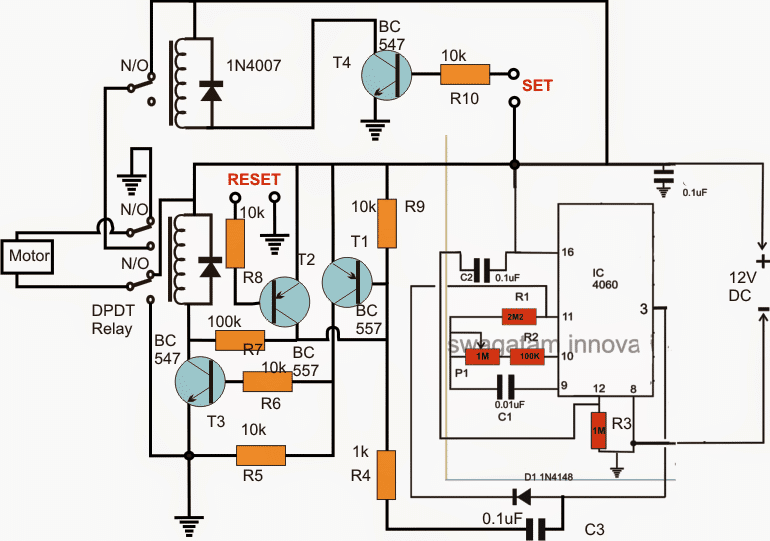
In the figure above we can visualize a design for implementing the proposed reverse forward motion of an incubator motor after a predetermined set of time interval.
At the instant when power is switched ON we have the following scenario:
The magnetic switch for "set" may be assumed to be in a deactivated state or depressed while the motor or the designed incubator mechanism is in its zero start position.
Please note that preferably the "set"/"reset" switches should be implemented using magnetic reed switches.
With power is switched ON, IC 4060 is reset via C2 so that it initiates it counting process from zero, and pin3 is rendered a zero logic.
This initial zero logic is fed via C3 to the base of T1 which instantly conducts forcing T3 and its associated relay to activate. R7 in the process makes sure T1/T3 get latched in this mode.
The DPDT relay at this point actuates at its N/O contacts initiating the motor and the mechanism towards an assumed "forward" motion.
As soon the motor begins moving, the "set" button is released such that T4 and the upper SPDT gets an opportunity to actuate, wherein the SPDT relay attains a N/O position changeover rendering the N/C contacts of the DPDT with a standby supply..
The motor and/or the mechanism keeps moving until it has attained the "reset" position which causes T2 to activate and break the T1/T4 latch.
With T4 switched OFF, the DPDT relay changes its position from N/O to N/C and provides an opposite (reverse) movement to the motor mechanism.
The incubator motor mechanism now flips its direction and initiates a reverse motion until it has reached the "set" point which quickly switches OFF the base drive of T4, the SPDT switches OFF cutting power of the DPDT and the entire mechanism comes to a stand still.
In the meantime the IC 4060 continues counting until it has yet again produced a zero logic after going through a high logic at its pin3 (by discharging C3).
The cycle once again gets initiated and repeats the procedure as explained above.


Questions & Answers
Egg Turning automatically 3 times per 24 hrs.
Dear sir
Please help me sir about washing machine motor when I m powerthe circuit motor run forward direction for 2 minits after 2minits motor stop 10 second than reverse for 2 minutes after 2 minutes motor stop 10second.than agen forward for 2 minutes.it was continued.i hope please help me as soon as possible.thank you sir
Hi Manoj,
I think i have already posted a similar looking circuit in this blog, you can find it in the following article:
https://www.homemade-circuits.com/washing-machine-motor-agitator-timer/
Please Swagatam, I need a similar design and wish you can help me. mine should work like this.
It is an automatic drying system which uses the sun.
1. When there is sun and no rain, the motor drives the drying tray into the sun. The motor stops automatically when the drying tray is fully out of the shed
2. when there is rain or darkness, the motor drives the drying tray into a shed (there should be a sensor that stops the motor automatically).
3. When the rain stops and there is sun the motor should drive the drying tray out off the shed into the sun again for drying to continue. The cycle continue.
Please it can be any motor but a DC motor is preferred. Thank u.
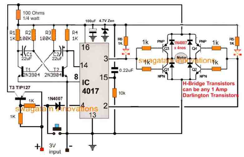
Hello Kofy, you can try the following simple design:
The two switches are push-to-OFF switches which work like limit switches. These must be positioned across the two extreme ends of the tray travel such that when the tray reaches the respective ends it pushes the switches to switch them OFF alternately.
The LDRs must be positioned under direct sunlight and must be fixed close to each other so that the LDR is subjected to the sunlight and shadow simultaneously and uniformly.
Remember this a crude design and the response may not be too accurate, and you may also have to adjust a few resistor values to make it work reasonably accurately.
Hi Jhay, the above circuit will not be appropriate for that….you can use the following instead
https://www.homemade-circuits.com/2012/04/how-to-make-simple-programmable-timer.html
Gudday sir swag im jhay from philippines how to revise the time set up of timer,from your diagram for example i need. 10sec. Power on,and 4hours power off..thanks in advance
Sir I want to make a transmitter and receiver for control a dc motor(speed and reverse forward). So tell me circuit diagram. My gmail- bayensuman90@gmail.com
Suman, I'll try to explain it through a new article soon….
Sir good day! Do the circuit includes the timer for turning it back and forth for the next cycle. Or it needs a separate preset timer for the next cycle.. im planning to adopt your circuit on my incubator project…thanks a lot.
thanks a lot sir.
good day teves! yes the IC 4060 can be set to repeat the reverse/forward motion infinitely, with any desired predetermined length of time
C1 and P1 can be altered, or modified for setting up the delay intervals.
hi mr Swag
can i use this design to drive a 220v AC small motor for my incubator mechanism?how can i remove the reverse function? and how can i control the time delay?hoping for your response.
many thanks…Apol
Hi Apol,
yes you can use it for your mentioned application, but without a reverse function how do you bring the motor back to its original position? please let me know about this so that i can solve it correctly for you.
Sir I am student. I want to make above mention circuit on PCB. Which software i use for it to make same circuit for PCB. Thank you
I personally use CorelDraw for designing PCBs and schematics, I have no idea about other softwares.
hello sir , i want to make a wifi signal detector can you please give me the circiut
Hello yasir, if I find it I'll surely post it for you