• Skip to main content
  • Skip to primary sidebar

Homemade Circuit Projects

Need circuit help? Post them in the comments! I've answered over 50,000!

Blog | Categories | About | Hire Me | Contact | Calculators-online
You are here: Home / Datasheets and Components / IRFZ44 Datasheet [55V 49 Amp N-channel MOSFET]

IRFZ44 Datasheet [55V 49 Amp N-channel MOSFET]

Last Updated on May 18, 2026 by Swagatam 12 Comments

The IRFZ44 is a popular N-channel power MOSFET designed for high current applications. Here is a detailed datasheet of the IRFZ44 MOSFET:

Table of Contents
  • General Information:
  • Pinout Configuration:
  • Electrical Characteristics:
  • Thermal Characteristics:
  • Features:
  • Applications:
    • Inverter circuit using IRFZ44
    • Conclusion

General Information:

  • Manufacturer: International Rectifier (now part of Infineon Technologies)
  • Model: IRFZ44
  • Type: N-channel power MOSFET
  • Package: TO-220AB

Pinout Configuration:

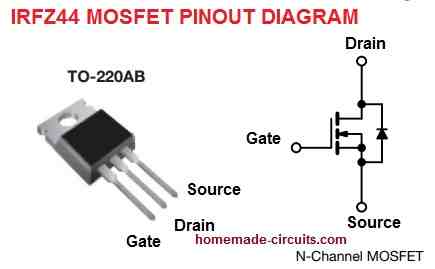
The following shows the pinout configuration for the MOSFET IRFZ44:
Electrical Characteristics:

  • Drain-Source Voltage (VDS): 55V
  • Continuous Drain Current (ID): 49A @ 25°C, 35A @ 100°C
  • Maximum Power Dissipation (PD): 94W @ 25°C
  • Gate-Source Voltage (VGS): ±20V
  • Drain-Source On-Resistance (RDS(on)): 17.5mΩ @ VGS=10V, ID=27A
  • Gate Threshold Voltage (VGS(th)): 2V to 4V
  • Input Capacitance (Ciss): 1320pF @ VDS=25V, VGS=0V, f=1MHz
  • Output Capacitance (Coss): 310pF @ VDS=25V, VGS=0V, f=1MHz
  • Reverse Transfer Capacitance (Crss): 225pF @ VDS=25V, VGS=0V, f=1MHz
  • Total Gate Charge (Qg): 47nC @ VGS=10V, ID=27A
  • Gate-Source Charge (Qgs): 7nC @ VGS=10V, ID=27A
  • Gate-Drain Charge (Qgd): 12nC @ VGS=10V, ID=27A

Thermal Characteristics:

  • Thermal Resistance, Junction-to-Ambient (RθJA): 62°C/W
  • Thermal Resistance, Junction-to-Case (RθJC): 1.5°C/W
  • Operating Junction Temperature Range (TJ): -55°C to 175°C
  • Storage Temperature Range (TSTG): -55°C to 175°C

Features:

  • Low RDS(on) for high efficiency
  • Fast switching speed for improved performance
  • High current handling capability
  • Low gate drive requirements
  • High input impedance
  • Avalanche energy rated
  • RoHS compliant

Applications:

The MOSFET IRFZ44 is commonly used for the following applications:

  • DC-DC converters
  • DC to AC 50 Hz, 60 Hz Inverters
  • Switching power supplies
  • Motor control
  • Solenoid and relay drivers
  • High frequency inverters
  • Class D audio amplifiers
  • Electronic ballasts
  • Battery chargers
  • Welding equipment

Inverter circuit using IRFZ44
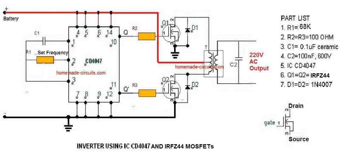
IRFZ44 inverter circuit

Conclusion

Overall, the IRFZ44 MOSFET is a high-performance, reliable device that can be used in a wide range of applications. Its low RDS(on), fast switching speed, and high current handling capability make it an ideal choice for power electronics applications.

You'll also like:

  • IC LM7912, -12V Negative Voltage Regulator Explained
  • lm35LM35 Pinout, Datasheet, Application Circuit
  • LMC555 pinoutsCMOS IC LMC555 Datasheet – Works with 1.5 V Supply
  • IC 4026 Datasheet, Pinout Working, Application

Filed Under: Datasheets and Components Tagged With: 55V, Channel, Datasheet, IRFZ44, MOSFET

About Swagatam

I am an electronics engineer and doing practical hands-on work from more than 15 years now. Building real circuits, testing them and also making PCB layouts by myself. I really love doing all these things like inventing something new, designing electronics and also helping other people like hobby guys who want to make their own cool circuits at home.

And that is the main reason why I started this website homemade-circuits.com, to share different types of circuit ideas..

If you are having any kind of doubt or question related to circuits then just write down your question in the comment box below, I am like always checking, so I guarantee I will reply you for sure!


Previous Post: « Tracking Transmitter Circuit
Next Post: Op amp IC 741 Datasheet, Pinout, Applications »

Reader Interactions

Questions & Answers

Total Posts: 12
Newest Oldest
Madison
June 20, 2023 • 3 years ago #143583

Hello, would this mosfet be ok being driven at 33kHz from an SG3525 without a mosfet driver?

Reply
SwagatamAdmin
June 21, 2023 • 3 years ago #143591

Yes, it’s OK, just make sure to incorporate a gate resistor and a diode as indicated in the following diagram:

howtopreventmosfetfromburning

The resistor value can be 10 ohms

Reply
Madison
June 21, 2023 • 3 years ago #143585

Hello could I drive this high frequency with a TL494? 30kHz

Reply
SwagatamAdmin
June 21, 2023 • 3 years ago #143592

Yes you can.

Reply
Madison
June 22, 2023 • 3 years ago #143609

Thank you very much! I will add the gate diode hopefully that will help my mosfet heating problem.

Reply
SwagatamAdmin
June 22, 2023 • 3 years ago #143610

Sure, no problem!

Reply
Madison
June 22, 2023 • 3 years ago #143611

I have read several places that switching off quickly is much more important than switching on quickly. Do you have any idea why this could be?

Reply
SwagatamAdmin
June 23, 2023 • 3 years ago #143617

Yes that’s correct, that is why we use a BJT driver stage at the gate or a reverse diode across the gate resistor. Quick switch OFF of the gate ensures quick discharge of the internal capacitance of the MOSFET gate and lower heat on the MOSFET.

Reply
Madison
June 23, 2023 • 3 years ago #143630

Nice! Even would the diode would’nt the switch off time be limited by the current sink capability of the SG3525?

Reply
SwagatamAdmin
June 23, 2023 • 3 years ago #143635

Without the diode the current has to pass through the gate resistor which can be slower, with a diode it becomes faster.

Reply
Madison
June 23, 2023 • 3 years ago #143640

Is this diode important with an IGBT as well?

Reply
SwagatamAdmin
June 23, 2023 • 3 years ago #143644

I think yes, since an IGBT also has a gate just like a MOSFET

Reply

Need Help? Please Leave a Comment! We value your input—Kindly keep it relevant to the above topic! Cancel reply

Your email address will not be published. Required fields are marked *

Primary Sidebar


Categories

  • Arduino Projects (95)
  • Audio and Amplifier Projects (134)
  • Automation Projects (18)
  • Automobile Electronics (103)
  • Battery Charger Circuits (89)
  • Datasheets and Components (109)
  • Electronics Theory (150)
  • Energy from Magnets and Earth (40)
  • Games and Sports Projects (11)
  • Grid and 3-Phase (20)
  • Health related Projects (27)
  • Home Electrical Circuits (13)
  • Indicator Circuits (16)
  • Inverter Circuits (100)
  • Lamps and Lights (163)
  • Meters and Testers (72)
  • Mini Projects (28)
  • Motor Controller (68)
  • Oscillator Circuits (30)
  • Pets and Pests (15)
  • Power Supply Circuits (91)
  • Remote Control Circuits (50)
  • Security and Alarm (65)
  • Sensors and Detectors (107)
  • SMPS and Converters (46)
  • Solar Controller Circuits (62)
  • Temperature Controllers (44)
  • Timer and Delay Relay (50)
  • Voltage Control and Protection (44)
  • Water Controller (37)
  • Wireless Circuits (31)


Circuit Simulator

circuit simulator image


Subscribe to get New Circuits in your Email


Other Links

  • Privacy Policy
  • Cookie Policy
  • Disclaimer
  • Copyright
  • Videos
  • Sitemap

People also Search

555 Circuits | 741 Circuits | LM324 Circuits | LM338 Circuits | 4017 Circuits | Ultrasonic Projects | SMPS Projects | Christmas Projects | MOSFETs | Radio Circuits | Laser Circuits | PIR Projects |


Recent Comments

  • Swagatam on Blood Electrification Circuit: Explanation And Working Principle
  • Ron Shenk on Blood Electrification Circuit: Explanation And Working Principle
  • Swagatam on 2 Cool 50 Watt Inverter Circuits for Students and Hobbyists
  • way on 2 Cool 50 Watt Inverter Circuits for Students and Hobbyists
  • Swagatam on 2 Cool 50 Watt Inverter Circuits for Students and Hobbyists

Social Profiles

  • Twitter
  • YouTube
  • Instagram
  • Pinterest
  • My Facebook-Page
  • Stack Exchange
  • Linkedin

© 2026 · Swagatam Innovations