• Skip to main content
  • Skip to primary sidebar

Homemade Circuit Projects

Need circuit help? Post them in the comments! I've answered over 50,000!

Blog | Categories | About | Hire Me | Contact | Calculators-online
You are here: Home / Datasheets and Components / IRF640 Datasheet [200V, 18 Amp N-Channel MOSFET]

IRF640 Datasheet [200V, 18 Amp N-Channel MOSFET]

Last Updated on May 18, 2026 by Swagatam 8 Comments

IRF640 is a N-channel Power MOSFET designed for applications such as switch mode power supplies (SMPS), DC-DC converters, motor control, and general purpose switching.

Table of Contents
  • Pinout Configuration
  • Electrical Characteristics:
  • Thermal Characteristics:
  • Mechanical Characteristics:
    • Package Information:
  • Applications
  • Making a 12V to 110V Boost Converter Circuit

Here is the complete datasheet for the IRF640:

Pinout Configuration

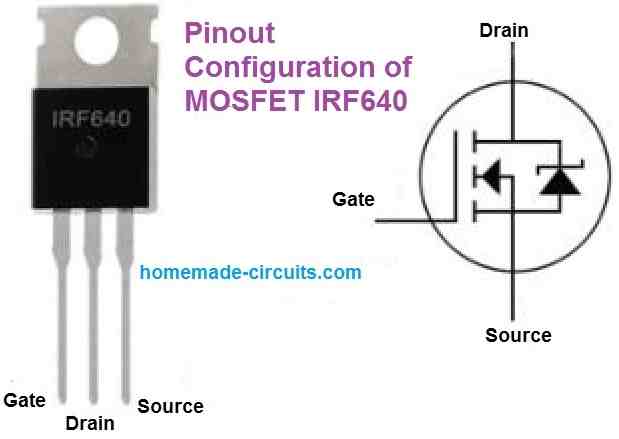
The pinout configuration of the MOSFET IRF640 is as given in the following diagram.
Electrical Characteristics:

  • Drain-Source Voltage (Vds): 200V
  • Continuous Drain Current (Id): 18A
  • Pulsed Drain Current (Idm): 72A
  • Gate-Source Voltage (Vgs): +/- 20V
  • Continuous Source Current (Is): 18A
  • Total Power Dissipation (Pd): 150W
  • Avalanche Energy (Eas): 170mJ
  • Avalanche Current (Iar): 18A
  • Threshold Voltage (Vth): 4V - 5V
  • Input Capacitance (Ciss): 1500pF
  • Output Capacitance (Coss): 500pF
  • Reverse Transfer Capacitance (Crss): 250pF

Thermal Characteristics:

  • Operating Junction Temperature (Tj): -55°C to 175°C
  • Storage Temperature (Tstg): -55°C to 175°C
  • Thermal Resistance, Junction-to-Case (RθJC): 1.25°C/W
  • Thermal Resistance, Junction-to-Ambient (RθJA): 62.5°C/W

Mechanical Characteristics:

  • Lead Temperature (TL): 300°C (soldering, 10 seconds)
  • Mounting torque: 1.1 Nm (10 lbf-in)

Package Information:

  • TO-220AB package with through-hole mounting

Applications

SMPS: The IRF640 can be utilised in SMPS for applications requiring voltage control and power conversion.

DC to DC Converters: MOSFETs are used in DC-DC converters to transfer electricity from one voltage level to another in an effective manner.

Motor Control: Applications involving the speed and direction control of DC motors and stepper motors are also carried out using the IRF640.

Audio Power Amplifiers: The MOSFET may be utilized as an output device to regulate the current flowing through the load in audio power amplifiers.

Lighting: Light-emitting diodes (LEDs), LED drivers, and high-intensity discharge (HID) lamps are some examples of lighting applications for the IRF640.

Solar Controller: IRF640 MOSFET can be utilized in solar power systems for voltage and current regulation as well as power conversion.

High Voltage Switch: Many applications requiring high current and voltage ratings can use the IRF640 as a general-purpose switch.

Making a 12V to 110V Boost Converter Circuit

The IRF640 MOSFET can be effectively used for making a 12V to 110V boost converter circuit as shown in the following diagram.
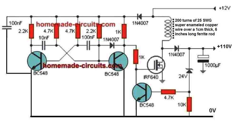
NOTE: Please make sure to replace the 24V zener diode with a 110V zener diode

You'll also like:

  • 188transistordatasheetBEL188 Transistor – Specification and Datasheet
  • BQ24295 Smart Battery Charger IC with Boost + OTG
  • r3Understanding Color Codes of Resistors with Practical Examples
  • thermistorTypes of Thermistors, Characteristic Details and Working Principle

Filed Under: Datasheets and Components Tagged With: 200V, Channel, Datasheet, IRF640, MOSFET

About Swagatam

I am an electronics engineer and doing practical hands-on work from more than 15 years now. Building real circuits, testing them and also making PCB layouts by myself. I really love doing all these things like inventing something new, designing electronics and also helping other people like hobby guys who want to make their own cool circuits at home.

And that is the main reason why I started this website homemade-circuits.com, to share different types of circuit ideas..

If you are having any kind of doubt or question related to circuits then just write down your question in the comment box below, I am like always checking, so I guarantee I will reply you for sure!


Previous Post: « IRF510 Datasheet [100V, 5.6 Amp, N-Channel MOSFET]
Next Post: How to Calculate Capacitors in Series and Parallel »

Reader Interactions

Questions & Answers

Total Posts: 8
Newest Oldest
obrien emmanuel chansa
September 21, 2024 • 2 years ago #161135

I want to make an inverter with a Irf640, with a low pas filter on the output, would you help me with a schematic. chansa from Zambia.

Reply
SwagatamAdmin
September 22, 2024 • 2 years ago #161175

Please provide the battery, load and waveform specifications of the inverter, i will try to help!

Reply
Wiseman
July 27, 2024 • 2 years ago #156111

Howsit man
I’m curious and eager to know if I can make a voltage regulator using mp1620 and a irf620n mosfet, can you please guide me through the steps if possible. Thanks

Reply
SwagatamAdmin
July 27, 2024 • 2 years ago #156126

Hi Wiseman,
Sure, you can certainly make a voltage regulator using IRF620 MOSFET. You can try the following configuration, and replace the MOSFET accordingly.
Mosfet regulator 300v circuit
Please remember the input voltage must not exceed 150V, and the entire circuit is not isolated from the input high voltage, so be extremely careful…

Reply
Shabbir
May 14, 2024 • 2 years ago #152273

Sir , specifications of how to design induction coil IC irs2453. .

Reply
SwagatamAdmin
May 14, 2024 • 2 years ago #152281

Hello Shabbir, i do not have this circuit with me at the moment, so i am unable to provide you any help regarding this topic.

Reply
A.G.Suresh Babu
December 7, 2023 • 3 years ago #147766

Dear Swagatham, is the current limited to the rating of zener diode or that of mosfet ?

Reply
SwagatamAdmin
December 8, 2023 • 3 years ago #147771

Dear Suresh,
The maximum output current is determined by the MOSFET rating, the zener diode decides the maximum output voltage.

Reply

Need Help? Please Leave a Comment! We value your input—Kindly keep it relevant to the above topic! Cancel reply

Your email address will not be published. Required fields are marked *

Primary Sidebar


My Youtube Channel

Circuit Simulator

circuit simulator image


Subscribe to get New Circuits in your Email


Categories

  • Arduino Projects (95)
  • Audio and Amplifier Projects (134)
  • Automation Projects (18)
  • Automobile Electronics (103)
  • Battery Charger Circuits (88)
  • Datasheets and Components (109)
  • Electronics Theory (149)
  • Energy from Magnets and Earth (40)
  • Games and Sports Projects (11)
  • Grid and 3-Phase (20)
  • Health related Projects (27)
  • Home Electrical Circuits (13)
  • Indicator Circuits (16)
  • Inverter Circuits (100)
  • Lamps and Lights (162)
  • Meters and Testers (72)
  • Mini Projects (28)
  • Motor Controller (68)
  • Oscillator Circuits (28)
  • Pets and Pests (15)
  • Power Supply Circuits (91)
  • Remote Control Circuits (50)
  • Security and Alarm (65)
  • Sensors and Detectors (107)
  • SMPS and Converters (45)
  • Solar Controller Circuits (61)
  • Temperature Controllers (43)
  • Timer and Delay Relay (50)
  • Voltage Control and Protection (44)
  • Water Controller (37)
  • Wireless Circuits (31)


Other Links

  • Privacy Policy
  • Cookie Policy
  • Disclaimer
  • Copyright
  • Videos
  • Sitemap

People also Search

555 Circuits | 741 Circuits | LM324 Circuits | LM338 Circuits | 4017 Circuits | Ultrasonic Projects | SMPS Projects | Christmas Projects | MOSFETs | Radio Circuits | Laser Circuits | PIR Projects |


Recent Comments

  • Swagatam on How to Modify SMPS for Adjustable Current and Voltage Output
  • Swagatam on Pure Sine Wave Inverter Circuit Using IC 4047
  • Johan on Pure Sine Wave Inverter Circuit Using IC 4047
  • Swagatam on DPDT Relay Working, Pinouts, Testing Explained
  • Swagatam on DPDT Relay Working, Pinouts, Testing Explained

Social Profiles

  • Twitter
  • YouTube
  • Instagram
  • Pinterest
  • My Facebook-Page
  • Stack Exchange
  • Linkedin

© 2026 · Swagatam Innovations