• Skip to main content
  • Skip to primary sidebar

Homemade Circuit Projects

Need circuit help? Post them in the comments! I've answered over 50,000!

Blog | Categories | About | Hire Me | Contact | Calculators-online
You are here: Home / Datasheets and Components / IC 4026 Datasheet, Pinout Working, Application


IC 4026 Datasheet, Pinout Working, Application

Last Updated on May 18, 2026 by Swagatam 1 Comment

IC 4026 is comprised of a 5-stage Johnson decade counter and an output decoder that transforms the Johnson code into a 7-segment decoded output to drive a single 7 segment numerical display. These devices offer significant advantages in display applications that prioritize low power dissipation and/or low package count.

Table of Contents
  • Pinout Configuration
  • Absolute Maximum Ratings:
  • Electrical Characteristics:
    • Applications:
    • Digital Counter Circuit using IC 4026

Both sides of IC 4026 have common inputs, including CLOCK, RESET, and CLOCK INHIBIT, while common outputs include CARRY OUT and the seven decoded outputs (a, b, c, d, e, f, g). CD4026 also features additional inputs and outputs, such as the DISPLAY ENABLE input and DISPLAY ENABLE and UNGATED "C-SEGMENT" outputs.

When a high RESET signal is applied, the decade counter is reset to its zero count. The counter advances one count on the positive transition of the clock signal, provided the CLOCK INHIBIT signal is low. Counter advancement through the clock line is blocked when the CLOCK INHIBIT signal is high.

The CLOCK INHIBIT signal can function as a negative-edge clock when the clock line is held high. The JOHNSON counter has antilock gating, which ensures proper counting sequence.

The CARRY-OUT (Cout) signal completes one cycle every ten CLOCK INPUT cycles, and it is utilized to clock the next decade directly in a multi-decade counting chain.

The seven decoded outputs (a, b, c, d, e, f, g) activate the appropriate segments in a seven-segment display device used to represent decimal numbers 0 to 9. The CD4026 outputs are only activated when the DISPLAY ENABLE IN is high.

The IC 4026 series type is available in 16-lead dual-in-line plastic packages (E suffix), 16-lead small-outline packages (NSR suffix), and 16-lead thin shrink small-outline packages (PW and PWR suffixes).

Pinout Configuration
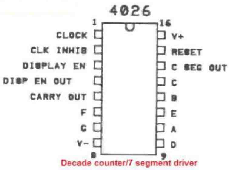
  • Pin 1: This is the Clock input pin, where an external clock signal should be applied.
  • Pin 2: This is the Clock inhibit pin. Connecting this pin to +Vcc, causes the IC to reject the clock input. When connected to GND, this causes the IC to accepts input clock pulses.
  • Pin 3: This is the Display enable / disable pin. When connected to +Vcc, it enables the 7 segment pins (A to G) so that they become active. When connected to GND it disables all the display pins.
  • Pin 5: This pin works in the divide by 10 mode or carry-out. This pin is turned high for every 10th input pulse. This pinout becomes useful when number of IC 4026 are cascaded to operate so that 2 or more digits can be used at the output.
  • Pins 6, 7, 9, 10, 11, 12,13: All these pinouts are the output pins for common cathode 7 segment display (A to G).
  • Pins 16 and 8 are +Vcc and GND respectively.
  • Pin 15: This pinout is the Reset pin. When this pin is connected to the supply positive the counting process is reset to zero. To enable normal counting operation of the IC this pin must be grounded.

Absolute Maximum Ratings:

  • Supply Voltage (Vdd): 18V
  • Input Voltage (All inputs): -0.5V to Vdd + 0.5V
  • Output Voltage (All outputs): -0.5V to Vdd + 0.5V
  • Operating Temperature Range: -55°C to 125°C
  • Storage Temperature Range: -65°C to 150°C

Electrical Characteristics:

  • Supply Voltage Range: 3V to 15V
  • Supply Current (Quiescent): 5uA typical, 10uA max.
  • Supply Current (Active): 3.5mA typical, 10mA max.
  • Clock Frequency Range: DC to 5MHz
  • Output Voltage (High): 90% of Vdd min.
  • Output Voltage (Low): 10% of Vdd max.
  • Propagation Delay Time: 70ns typical, 100ns max.

Applications:

  • Digital counters
  • 7-segment display drivers
  • Timers and clocks
  • Frequency dividers
  • Decade counters

Two practical application circuits can be learned in the following links:

Visitor Counter Circuit Using IC 555 and IC 4026

Vehicle Parking Lot Counter Circuit

Digital Counter Circuit using IC 4026

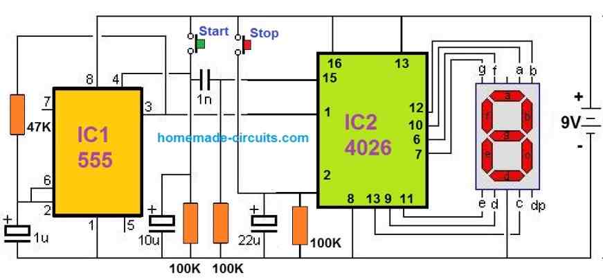
The following diagram explains how to build a simple digital frequency counter using the IC 4026.
You'll also like:

  • IC4047basicconfigurationIC 4047 Datasheet, Pinouts, Application Notes
  • Isolated High Side Gate Driver Opto-Coupler HCPL3120: No need of Bootstrapping Capacitor/Diode
  • ujt 2n2646Unijunction Transistor (UJT) 2N2646 Datasheet
  • mje13005pinoutdiagramHigh Voltage Transistor MJE13005 – Datasheet, Application Notes

Filed Under: Datasheets and Components Tagged With: 4026, Application, Datasheet, Pinout, Working

About Swagatam

I am an electronics engineer and doing practical hands-on work from more than 15 years now. Building real circuits, testing them and also making PCB layouts by myself. I really love doing all these things like inventing something new, designing electronics and also helping other people like hobby guys who want to make their own cool circuits at home.

And that is the main reason why I started this website homemade-circuits.com, to share different types of circuit ideas..

If you are having any kind of doubt or question related to circuits then just write down your question in the comment box below, I am like always checking, so I guarantee I will reply you for sure!


Previous Post: « IC 4020 Datasheet, Pinout Functioning Explained
Next Post: IC 4025 Datasheet, Pinout Working, Application »

Reader Interactions

Questions & Answers

Total Posts: 1
Newest Oldest
JOHN T SCHNEIDER
April 18, 2023 • 3 years ago #141878

MANY PEOPLE TALK ABOUT THE CD4026 AND SHOW A ONE OR TWO DIGIT SCHEMATIC, BUT NO ONE SEEMS TO KNOW HOW TO MAKE THE CD4026 DIVIDE BY 60 OR 12 FOR CLOCK CIRCUITS. DO YOU KNOW?

Reply

Need Help? Please Leave a Comment! We value your input—Kindly keep it relevant to the above topic! Cancel reply

Your email address will not be published. Required fields are marked *

Primary Sidebar

My YouTube Channel

Circuit Simulator: Draw and Simulate Schematics

circuit simulator image


Categories

  • Arduino Projects (95)
  • Audio and Amplifier Projects (134)
  • Automation Projects (18)
  • Automobile Electronics (104)
  • Battery Charger Circuits (90)
  • Datasheets and Components (109)
  • Electronics Theory (151)
  • Energy from Magnets and Earth (43)
  • Games and Sports Projects (11)
  • Grid and 3-Phase (20)
  • Health related Projects (27)
  • Home Electrical Circuits (13)
  • Indicator Circuits (16)
  • Inverter Circuits (98)
  • Lamps and Lights (161)
  • Meters and Testers (72)
  • Mini Projects (28)
  • Motor Controller (68)
  • Oscillator Circuits (30)
  • Pets and Pests (15)
  • Power Supply Circuits (91)
  • Remote Control Circuits (50)
  • Security and Alarm (65)
  • Sensors and Detectors (107)
  • SMPS and Converters (46)
  • Solar Controller Circuits (62)
  • Temperature Controllers (44)
  • Timer and Delay Relay (51)
  • Voltage Control and Protection (44)
  • Water Controller (37)
  • Wireless Circuits (31)


Subscribe to get New Circuits in your Email


Other Links

  • Privacy Policy
  • Cookie Policy
  • Disclaimer
  • Copyright
  • Videos
  • Sitemap

People also Search

555 Circuits | 741 Circuits | LM324 Circuits | LM338 Circuits | 4017 Circuits | Ultrasonic Projects | SMPS Projects | Christmas Projects | MOSFETs | Radio Circuits | Laser Circuits | PIR Projects |


Recent Comments

  • Swagatam on Adjustable Voltage Regulator Circuit using LM324 IC with Over Current Protection
  • Swagatam on Inverter Circuit with Feedback Control
  • Swagatam on Inverter Circuit with Feedback Control
  • Swagatam on Proximity Detector IC CS209A Pinouts – Datasheet Explained
  • PRAFUL WANDHARE on Proximity Detector IC CS209A Pinouts – Datasheet Explained

Social Profiles

  • Twitter
  • YouTube
  • Instagram
  • Pinterest
  • My Facebook-Page
  • Stack Exchange
  • Linkedin

Calculators

  • ZVS Induction Heater + Tank Calculator Tool
  • Zener Diode Calculator
  • Wire Current and Thickness Calculator (Ampacity Calculator)
  • Voltage Divider Calculator
  • Transistor Base Resistor Calculator
  • Transistor Astable Multivibrator Calculator
  • TL431 Calculator
  • Solar Panel, Inverter, Battery Calculator
  • Ferrite Core Air Gap Calculator Tool
  • Parallel MOSFET Calculator Tool: How to Connect MOSFETs in Parallel Safely
  • LC Resonance Calculator for EV Battery Charger Circuits
  • LED String Series Resistor Calculator
  • PFC (Power Factor Correction) Calculator Tool: 3kW
  • Passive Power Factor Correction (PFC) Calculator
  • LM567 IC Calculator Tool
  • SMPS Flyback Boost Converter Calculator
  • Shunt Resistor Calculator for Ammeters
  • SCR and Triac Gate Resistor Calculator
  • Battery Back up Time Calculator
  • Boost Converter Calculator (Non-Isolated)
  • Bootstrap Capacitor Calculator
  • Buck Converter Calculator
  • Buck-Boost Converter Calculator
  • Capacitance Reactance Calculator
  • DCM Flyback Transformer & Wire Gauge Wire Size Calculator Tool
  • Filter Capacitor Calculator
  • IC 4047 Calculator (Frequency and PWM)
  • IC 4060 Calculator
  • IC 555 Astable Calculator
  • IC 555 Monostable Calculator
  • IC SG3525, SG3524 Calculator
  • Inductance Calculator
  • Induction Heater Inductor and Resonant Frequency Calculator
  • Induction Heater Work Coil Calculator
  • Inverter LC Filter Calculator
  • LC Resonance Calculator
  • LED Current Calculator
  • LM317, LM338, LM396 Calculator
  • NAND/NOT Gate RC Values Calculator
  • NOT, NAND Gate Frequency Calculator
  • Notch Filter Calculator Tool
  • Ohm’s Law Calculator
  • Phase Angle Phase Shift Calculator
  • Power Factor (PF) Calculator
  • RC Filter Calculator
  • Reactance Calculator
  • Sine Table Calculator for SPWM Arduino Code
  • Small Signal Transistor(BJT) and Diode Quick Datasheet
  • SMPS Calculator for Toroidal Ferrite Transformers
  • SMPS Flyback Transformer Calculator – Design by Target Duty Cycle
  • TL431 Calculator
  • Op-Amp Hysteresis Resistor Calculator

© 2026 · Swagatam Innovations