• Skip to main content
  • Skip to primary sidebar

Homemade Circuit Projects

Get free circuit help 24/7

New Projects | Privacy Policy | About us | Contact | Disclaimer | Copyright | Videos 

You are here: Home / Datasheets / IRF510 Datasheet [100V, 5.6 Amp, N-Channel MOSFET]

IRF510 Datasheet [100V, 5.6 Amp, N-Channel MOSFET]

Last Updated on February 27, 2023 by Swagatam Leave a Comment

The IRF510 is a popular N-channel power MOSFET (Metal Oxide Semiconductor Field Effect Transistor) commonly used in electronic circuits for various applications, including audio amplifiers, power supplies, and switching circuits.

It is rated with a maximum voltage of 100 volts and a maximum current of 5.6 amps. These ratings makes the device suitable for medium to high power applications. The IRF510 MOSFET features a low on-resistance. Due to this feature it is able to switch optimal amounts of currents without dissipating too much power in the form of heat.

Electrical Characteristics:

  • Drain-Source Voltage (VDS): 100V
  • Continuous Drain Current (ID): 5.6A
  • Power Dissipation (PD): 43W
  • Gate-Source Voltage (VGS): ±20V
  • Total Gate Charge (Qg): 50nC
  • Threshold Voltage (VGS(th)): 2V to 4V
  • Drain-Source On-Resistance (RDS(on)): 0.5 ohms

Thermal Characteristics:

  • Junction Temperature (Tj): -55°C to 175°C
  • Thermal Resistance - Junction to Case (RθJC): 1.4°C/W
  • Thermal Resistance - Junction to Ambient (RθJA): 62.5°C/W
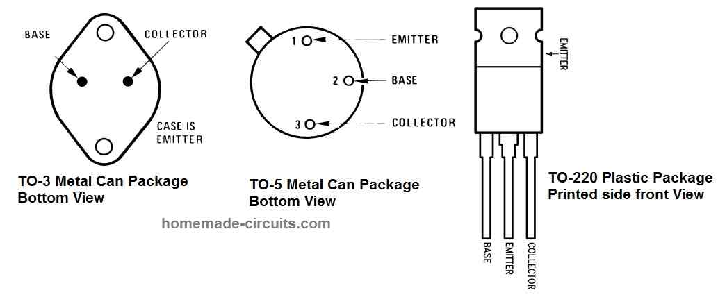
Pin Configuration:

caution electricity can be dangerous

The IRF510 MOSFET has three pins: the drain (D), the gate (G), and the source (S). The pinout configuration is as follows:

  • Pin 1: Gate (G)
  • Pin 2: Drain (D)
  • Pin 3: Source (S)

Package Information:

The IRF510 MOSFET is available in the TO-220 package, which is a through-hole package with a single mounting hole. The package dimensions are as follows:

  • TO-220 Package: 10.67mm x 15.87mm x 4.83mm

Typical Applications:

The IRF510 MOSFET is commonly used in power switching applications, such as:

  • Power supplies
  • Motor control
  • Audio amplifiers
  • RF amplifiers
  • Switching regulators
  • DC-DC converters

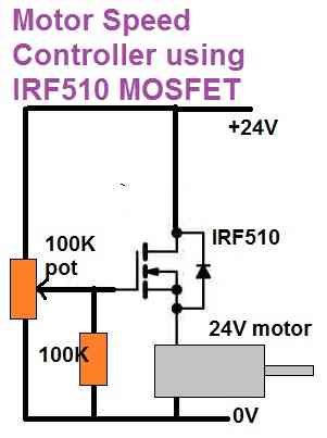
Simple Motor Controller Circuit

The IRF510 MOSFET can be used for making a simple DC motor speed controller circuit, as shown in the following diagram:

Absolute Maximum Ratings:

Please make sure the MOSFET IRF510 is not operated above the following absolute maximum ratings.

  • Maximum Drain-Source Voltage: 100V
  • Maximum Continuous Drain Current: 5.6A
  • Maximum Power Dissipation: 43W
  • Maximum Junction Temperature: 175°C
  • Maximum Gate-Source Voltage: ±20V

Other Features:

  • N-Channel MOSFET
  • Low Gate Threshold Voltage
  • Low On-Resistance
  • High Input Impedance

Note: This information is taken from the IRF510 datasheet published by Infineon Technologies. Actual values may vary based on specific manufacturer and production batch

You'll also like:

  • 1.  HX710B Air Pressure Sensor Datasheet, How to Connect
  • 2.  IRF540N MOSFET Pinout, Datasheet, Application Explained
  • 3.  BC636 Transistor Datasheet [45 V 1 Amp PNP Transistor]
  • 4.  L293 Quad Half-H Driver IC Pinout, Datasheet, Application Circuit
  • 5.  IC 4013 Datasheet, Pinout Details
  • 6.  IC 4026 Datasheet, Pinout Working, Application

About Swagatam

I am an electronic engineer (dipIETE ), hobbyist, inventor, schematic/PCB designer, manufacturer. I am also the founder of the website: https://www.homemade-circuits.com/, where I love sharing my innovative circuit ideas and tutorials.
If you have any circuit related query, you may interact through comments, I'll be most happy to help!

Have Questions? Please Comment below to Solve your Queries! Comments must be Related to the above Topic!!

Subscribe
Notify of
0 Comments
Inline Feedbacks
View all comments

Primary Sidebar

Categories

  • 3-Phase Power (15)
  • 324 IC Circuits (19)
  • 4017 IC Circuits (52)
  • 4060 IC Circuits (26)
  • 555 IC Circuits (99)
  • 741 IC Circuits (20)
  • Arduino Engineering Projects (83)
  • Audio and Amplifier Projects (115)
  • Battery Chargers (83)
  • Car and Motorcycle (94)
  • Datasheets (73)
  • Decorative Lighting (Diwali, Christmas) (33)
  • Electronic Components (101)
  • Electronic Devices and Circuit Theory (36)
  • Electronics Tutorial (120)
  • Fish Aquarium (5)
  • Free Energy (34)
  • Fun Projects (13)
  • GSM Projects (9)
  • Health Related (20)
  • Heater Controllers (29)
  • Home Electrical Circuits (103)
  • How to Articles (20)
  • Incubator Related (6)
  • Industrial Electronics (28)
  • Infrared (IR) (40)
  • Inverter Circuits (98)
  • Laser Projects (12)
  • LED and Light Effect (93)
  • LM317/LM338 (21)
  • LM3915 IC (25)
  • Meters and Testers (66)
  • Mini Projects (149)
  • Motor Controller (67)
  • MPPT (7)
  • Oscillator Circuits (26)
  • PIR (Passive Infrared) (8)
  • Power Electronics (34)
  • Power Supply Circuits (79)
  • Radio Circuits (10)
  • Remote Control (48)
  • Security and Alarm (61)
  • Sensors and Detectors (121)
  • SG3525 IC (5)
  • Simple Circuits (75)
  • SMPS (29)
  • Solar Controllers (61)
  • Timer and Delay Relay (53)
  • TL494 IC (5)
  • Transformerless Power Supply (8)
  • Transmitter Circuits (41)
  • Ultrasonic Projects (16)
  • Water Level Controller (45)

Calculators

  • AWG to Millimeter Converter
  • Battery Back up Time Calculator
  • Capacitance Reactance Calculator
  • IC 555 Astable Calculator
  • IC 555 Monostable Calculator
  • Inductance Calculator
  • LC Resonance Calculator
  • LM317, LM338, LM396 Calculator
  • Ohm’s Law Calculator
  • Phase Angle Phase Shift Calculator
  • Power Factor (PF) Calculator
  • Reactance Calculator
  • Small Signal Transistor(BJT) and Diode Quick Datasheet
  • Transistor Astable Calculator
  • Transistor base Resistor Calculator
  • Voltage Divider Calculator
  • Wire Current Calculator
  • Zener Diode Calculator

© 2023 · Swagatam Innovations

wpDiscuz