In this article I have explained a couple of inverter circuits featuring an automatic feedback control for ensuring that the output does not exceed the normal specified AC output level, and also does not exceed the specified overload conditions.
What is Feedback Control in Inverters
A feedback control in inverter is generally incorporated to control the output voltage and output current and prevent it from exceeding beyond dangerous limits.
In this system, the output AC mains voltage is first dropped to a proportionately lower level, and fed to the shut down pin of the control IC. The stepped down feedback voltage now follows the output AC and varies up/down accordingly, in a proportionate manner.
The control ICs shut down circuitry comares and monitors this feedback signal with a fixed ference derived from the battery volatge of the inverter.
In an event that the output voltage tends to rise above the predetermined value, and increase beyond the reference level, it activates the error amplifier, which shuts down the inverter output PWM. Once this happens, the output voltage instantly dips, causing the feedback signal to decrease below the reference value. This situation prompts the shut down feature of the IC to get disabled, and the IC starts working normally again.
If the output yet again tries to rise beyond the unsafe level, the above process is repeated in the identical manner, and this goes on continuously and rapidly, ensuring that the output voltage is never allowed to surpass the specified unsafe level.
Feedback Control in SG2524/SG3524 Inverters
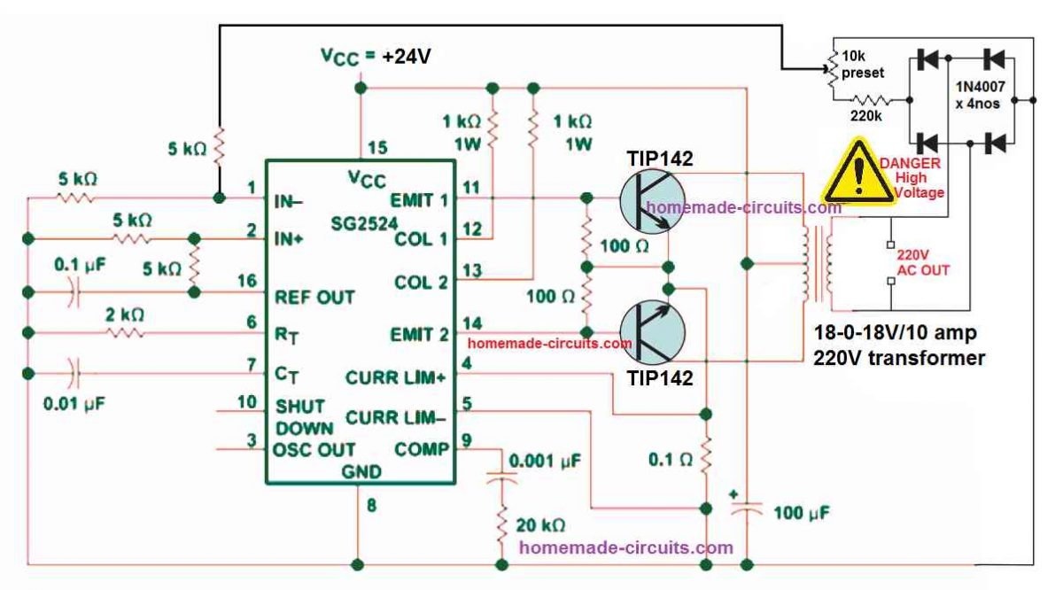
The first example circuit belw shows how an automatic feedback control can be added to a SG2524 inverter circuit. The same concept can be also applied to all the other inverter versions, using the IC SG3524, and SG3525.
You can refer to the following two datasheets for exactly knowing how the pinouts of the IC SG2524 IC are designed to function:
The feedback control loop is configured in the following can be understood with the following points:
The 220V AC output is first rectified using a 4 diode bridge rectifier circuit.
The rectified high voltage DC is dropped to a lower DC level, at around 5V to 10V through the voltage divider network built using the 220K resistors and the 10K preset.
The 10K preset is used to adjust the feedback voltage until the output voltage is controlled just at the right level.
The feedback is taken from the 10K preset's center arm and fed to the error amplifier's non-inverting input pin#1 of the IC 2524.
This error amplifier is nothing but an opamp set internal to the IC for controlling the PWM of the output pin#11 and Pin#14.
The inverting or the (+) input pin#2 of the op amp is clamped at a fixed reference level of +2.5V through the couple of voltage divider resistors configured around the pin#2 and pin#16 of the IC. The +5V reference potential is derived from pin#16 of the IC and then dropped to 2.5V using the two voltage divider resisters.
Since the pin#2 of the error amplifier is fixed at 2.5V reference, means that if the pin#1 of the opamp rises above the 2.5V level would instantly trigger the PWM feature of the IC, causing narrowing of the output PWM to the transistors.
The feedback 10k preset is adjusted in a such a way that feedback voltage at pin#1 reaches the 2.6 V mark as soon as the output voltage reaches the specified unsafe high voltage level.
In such situations, when the pin#1 receives a 2.6 V, it will cause the internal error amp to activate, narrowing the output PWMs to the transistors, which will in turn cause the output voltage to reduce to the safe lower levels, appropriately.
Simple Voltage Feedback Control for SG3525 Inverters
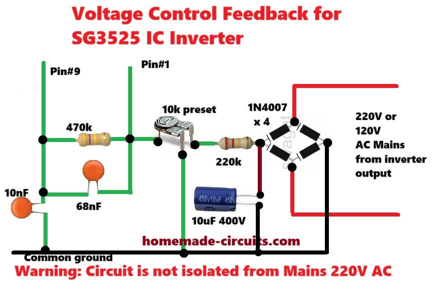
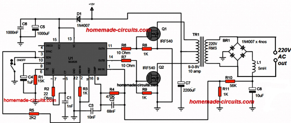
This is simple non isolated direct feedback circuit for SG3525 inverter. First high voltage 220 AC comes from inverter output. Then four 1N4007 diodes convert this AC into DC.
After that 220k resistor drops high voltage and 10uF four hundred volt capacitor smooths out DC ripple. Now 10k preset is used as voltage divider to set output voltage to220 or 120 volt. Sampled voltage directly goes to Pin number one of SG3525 IC.
Between Pin number 1 and Pin number 9 there is 470k resistor and 68nF capacitor network for error amplifier compensation to stop oscillation.
Also 10nF capacitor is connected from Pin number 9 to ground for extra filtering. When output AC voltage increases, voltage at Pin number 1 also goes up.
Since Pin 2 is supposed to be at fixed reference, high voltage at Pin 1 forces internal error amp to reduce duty cycle and output voltage comes back to normal level.
Main warning is that this whole circuit shares common ground with AC output, so it is not isolated and touching any part can give dangerous electric shock.
Adding Feedback in IC 555 Inverter
You might have already gone through the post which explains how to build simple 555 based inverters.
Although all these inverters are decently designed and will produce the intended 220 V or 120 V from an easy IC 555 set up, these do not have a built-in feedback system for ensuring a constant output voltage.
The following figure shows how an ordinary IC 555 inverter could be transformed into an enhanced inverter through an easy feedback loop control network.
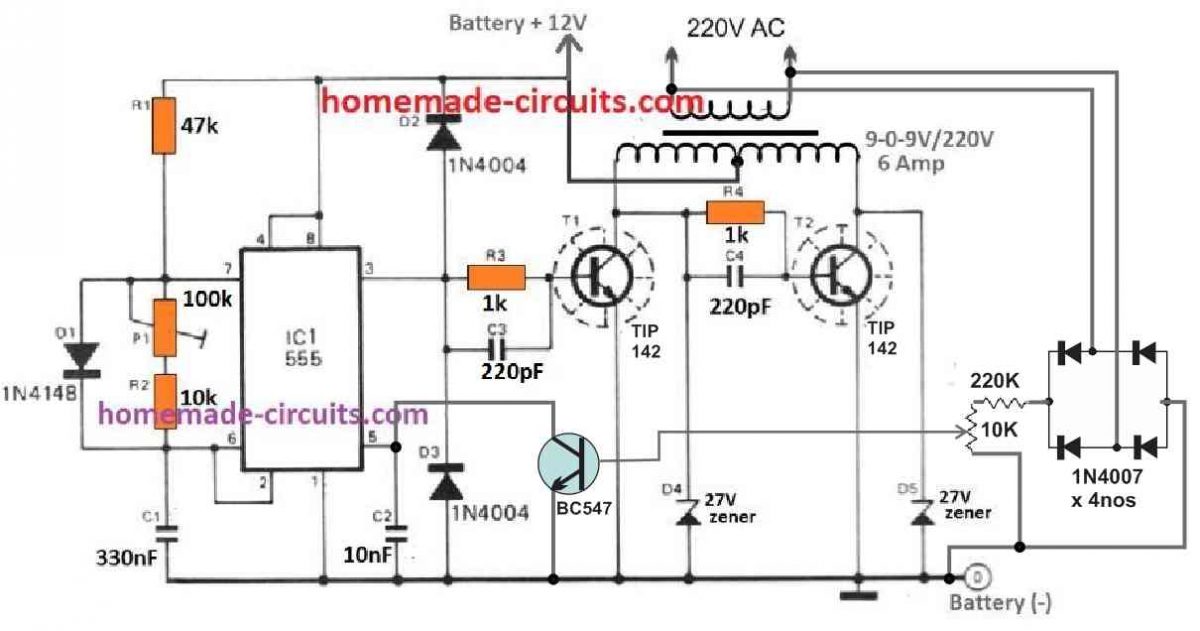
In this circuit also, we find that the 220V output from the transformer is first rectified to a DC level, and then it is stepped down through a resistive network comprising of a 220K resistor and a 10k preset.
The 10k preset center lead is configured with the NPN transistor BC547, whose collector can be seen connected with the pin#5 of the IC which is control input of the IC.
We know that normally when pin#5 is open, the PWM at the output pin#3 of the IC has a maximum PWM, however, as the potential at pin#5 is reduced, the output PWM also gets reduced proportionately.
Grounding the pin#5 causes the output PWM at pin#3 to become very narrow, with almost zero average voltage at this pinout.
In the IC 555 feedback circuit, when the output voltage tends to rise above the unsafe high voltage threshold, as per the setting of the 10k preset, the base of the BC547 slowly starts getting biased. When this happens, the BC547 begins conducting and causes the pin#5 of the IC to get gradually grounded. The grounding of the pin#5 of the IC causes the output PWM at pin#3 to get narrower, which in turns causes the output voltage to drop to the normal levels.



Questions & Answers
Good afternoon, sir. how is everything? well I am enjoying my inverter but I still want to make a better one, sir. pls sir is there anyway I can modify my inverter circuit to become modified square wave inverter, so that the range of load I can power can increase? maybe with ne555 or
..?
Hi Jerry,
To convert your existing SG3525 into a modified sine/sqaure wave inverter, you can increase the deadtime by upto 30%, then add a 1uF/400V capacitor at the secondary 220V AC side of the transformer.
Make sure your transformer voltage rating is 30% lower than the battery voltage, meaning if the battery voltage is 12V, then the transformer could be around 8-0-8V or 9-0-9V
Good morning, sir. I don’t know if my first message was sent. that is why I am sending this again. the ic I used is sg3524n ic. my transformer is 6.2v 0 6.2v to 220v. for the dead time how do I do it, sir? this is my inverter schematic.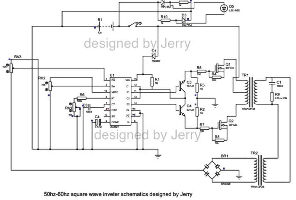
Sorry, my previous reply was for IC SG3525, not for SG3524.
I think it is better to use an external IC 555 PWM circuit for chopping the MOSFET gates for converting it into a modified or even a pure sine wave inverter…
Good Morning Jerry,
A resistor connected across this pin#7 and pin#5 will give you the dead time. Try a 100 ohm and check the response…
Hi sir, why is the feedback unstable? https://drive.google.com/file/d/1P1nT4NOcAflLR0wgv5w38ztkRjtSKv-W/view?usp=drivesdk
Johan, please make your circuit in this way, and then check:
I’ve checked but the voltage goes up and down https://drive.google.com/file/d/1PNzcsLdni5UE8shq1UUlGXNEHCU1RZ7i/view?usp=drivesdk
The feedback circuit which I gave is correct, I think the problem could be in your inverter circuit, please build the following circuit and check again:

Hi sir. It turns out that the correct one is that pin 9 of the SG3525 IC is fitted with a 4.7k rc resistor and a 2.2μF non-polar capacitor and pin 1 is connected to pin 9 which uses a 470k resistor and a 68nf capacitor.it has to be released and I have tested it and it no longer vibrates and the output is very stable
Thanks Johan, for updating the info, I am glad it is now working good for you good..
I made it using an isolated one using a small additional transformer for feedback using a voltage of 16v and the main transformer using a 600va ct 7v transformer using a 12v battery that has been tested to be capable of carrying the heavy load.
Thanks for the feedback and the useful information…
is it possible to achieve overload and shortcircuit protection using current transformer and op-amp in an inverter? If yes please help with a circuit diagram
Sure….Please refer to the following article:
https://www.homemade-circuits.com/load-current-control-through-current-sensing-transformer/
Swatan.. I don’t know where to ask,,, I would like a circuit to make an inverted welder of at least 120 Amp to 250 Amp, I have type E ferrite cores from televisions, also the circular or round ones from vehicle audio amplifiers,,, but I need a diagram if possible checked
Hi, a TV ferrite core or an audio amplifier ferrite core will not be able to produce 200 amp current.
Unfortunately, I do not seem to have sufficient information about the details of this transformer at the moment..
Good sir. I have a problem with my sg3524 circuit.
I built this inverter with feedback voltage correction circuitry but when power it, its actually working is giving out 220v as i set it but while working the mosfet is extremely hot. I try everything i could but could not rectify the problem but when ever i remove the feedback topology and return it back to the normal switching circuitry, it doesn’t hot at all but am not ok with the output as soon i inserted a load to it. It will drop from 220 to 140v.
I actually use 7.2v center tap transformer.
Hello Abdul,
Please add a snubber network across the MOSFETs as discussed in the following article, and also add a reverse diode across the gate resistors of the MOSFETs, and add a 10k resistor between gate and source of the MOSFETs, and check the results:
https://www.homemade-circuits.com/explained-snubber-circuit-for-mosfet-h-bridge/
https://www.homemade-circuits.com/rc-snubber-calculator-for-mosfets-relay-contacts-and-triacs/
https://www.homemade-circuits.com/mosfet-protection-basics-explained-is/
swatan,,,, pregunto si tendrías algún circuito que pueda hacer para un soldador tipo invertir, para hacer si me das un esquema y detalles lo haré soy experto en electrónica..
Felix, I have answered to your question previously, but no problem I will answer it again.
Designing Inverter type welding circuit is possible, but 250 amps is huge, I have no idea which ferrite core would be required for such high current application.
https://drive.google.com/file/d/1HJ1BjVdX1m5d9tyioweUeXkwcNFR9wXL/view?usp=drivesdk
this is what i finally did,the feedback is working,but there is catch under capacitive load the output increases e.g phone charger, capacitor etc.,but if I put a 40w resistive load (incandescent bulb) and then plug any capacitive load it remains stable and don’t increase, pls what is the cause?,apart from this it is working fine my MosFets are not getting warm too quickly.i also want to add battery low circuit and fuse pls any idea?sport for so many resend I don’t know if you will see this one.
Capacitive loads like phone chargers or plain capacitors mostly pull reactive power, not real power. Because of this, the inverter thinks there is not much load so voltage can rise or go unstable, mostly if the feedback is not properly designed. Now when you connect a resistive load like a bulb, it pulls real power continuously so inverter starts regulating voltage properly. After that even if you add capacitive loads, still the voltage stays stable because real load keeps things balanced.
So you can try adding a 1k resistor at the output and check the results…
that is the issue if am going to use a resistor for the real load then I should be prepared for how to reduce the heat it is going to generate,pls what should I do about that?,also if am to use 1k pls what Watt should I use?and can even get it here cause it is not available.
Instead of a resistive method, please try connecting a 10uF capacitor across the output of the bridge rectifier and check the results.
By the way your MOSFET driver section looks bad…you must use the methods which I had suggested earlier.
can 30uf/450v Ac capacitor and AC circuit breaker be used to stabilize inverter output voltage?
Please show me the circuit diagram, I will try to figure it out….
https://drive.google.com/file/d/1sDAfqSz0v9xgZB20mmUiM3PCMeF3gXIt/view?usp=drivesdk
what will happen if you remove the 10k resistor from the oscillator pin ,with it affect the performance,cause when I want to add the totem pole driver I remove mine and my inverter was misbehave was it responsible for that?
Whether or not you connect a 10k between the oscillator output and ground does not make any difference, and will not have not any kind of effect on the inverter performance.
sir, when I implemented circuit 1 into my oscillator,it worked, but then my feedback was affected,my inverter started Misbehaving the output was no longer stable again.was could be the cause?also my inverter is sensitive to capacitor at it output or even at feedback so what could be the cause?
Jerry, please do not associate any capacitor with the feedback network, however connecting a capacitor at the output of the inverter should not affect the inverter performance. Make sure the capacitor is a non-polar PPC or MKT type such a 2.2uF/400V PPC etc. Moreover you need this capacitor mostly when you are using a modified PWM or SPWM sinewave inverters topologies, otherwise it is not required.
good evening, sir. happy new year. it been a while like a year since I work on my diy inverter, since am in school, but few day ago, while reading a course called power electronics, where I was drawing the waveform of bridge rectifier, I realized I never understood them cause I used ur circuit to design my feedback circuit for my diy inveter although the oscillator circuit is different, the issues was I always thought that the anode if a diode is the positive terminal and cathode for gnd, this was the idea I had while designing the feedback for my diy inverter, I mentioned earlier that when I implemented it at first it work even with capacitive load, after neating and coupling the inverter it misbehaved, this use due to me connecting my positive of my feedback voltage to gnd and negative or gnd through the voltage divider to pin 1, I never released this till after a year, I tried my best to find the issues, till I don’t even remember what I did that made the while system work with the feedback, but still misbehaves with capacitive load, although after my exam if I go home I would open everything and inspect what I did, cause hmmm, until after a year that I realized how bridge rectifier works, and the anode of the diode will be your ground, I pray I don’t just chastise myself when I see all my connection in the inverter. about the driver I will fix them using 4 npn transistor(the second method you show me), am also thinking of rebuild the whole osillator surcuit using your circuit entirely, that will be for maybe a second inverter and lastly thanks for all the help and advice it really helped, alot!!. the website update is nice also👌👌.
pardon me if you see this message more than once, I don’t even know if it is sent or not, that is the reason for the multiple resend
I would like to add that a thought came to me, that I can utilize your transistor driver which drine the primary winding directly, but instead used it to drive the gate of a mosfet instead, is this also ok?
Thank you Jerry for your kind and honest feedback…I appreciate it very much.
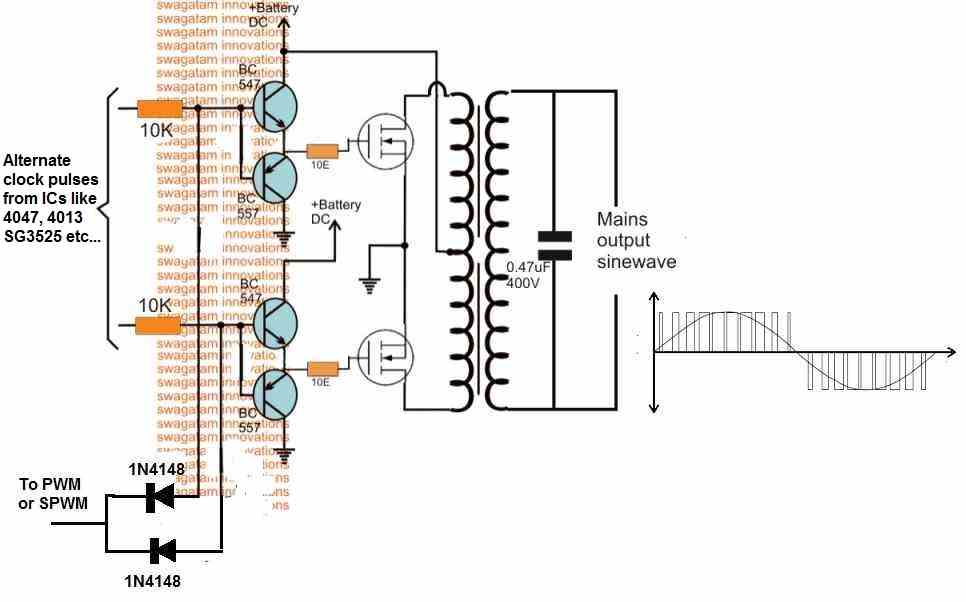
If you want to use a BJT driver for the MOSFET gates then make they are two of them connected in inverting mode, or in a totem pole mode.
Morning, sir. i am happy to announce that my inverter is up and running and these are the modification i made.

Thank you Jerry, it looks great, thank you for updating your tested design here…much appreciated.
what I was trying to say is that before I implemented the totem pole driver I already added feedback and it is working,when I power capacitive load with it it handles them also,but I noticed my mosfet got warm to quickly that is why I added the totem pole driver and on doing that the my inverter output stated misbehaving it was not stable going from 100v to 200v to and fro,but yesterday I added those 2 10k I mentioned to gnd and then I was able to finetune my feedback,but I added capacitive load and all of a sudden the voltage started fluctuating again,pls what is happening? thanks for your effort on me.
Then I think you should remove the totem pole and try the other driver configuration which I had suggested you using two NPN transistors. Make sure to connect each and every resistor correctly, otherwise it will not work:
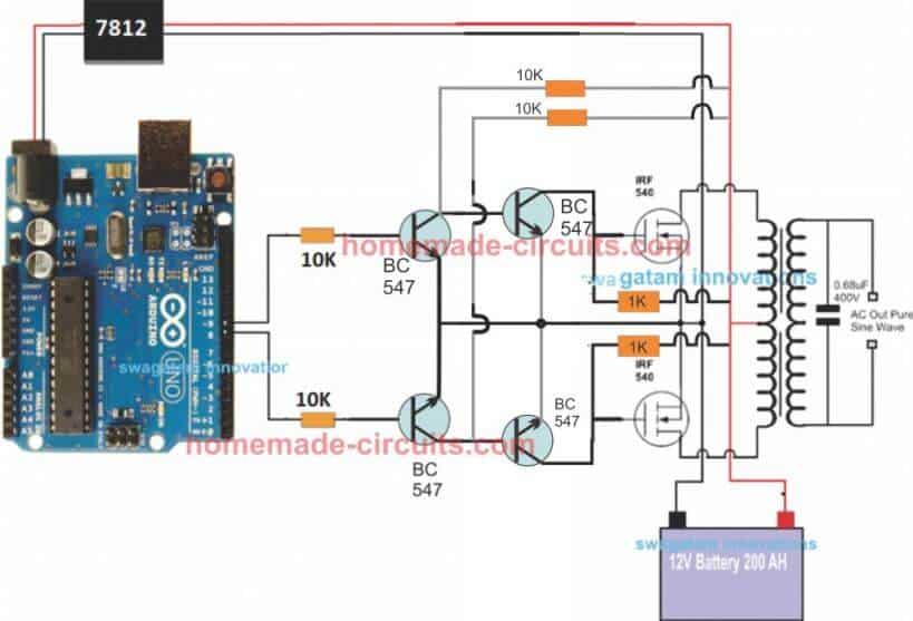
when I return my circuit to old no (totem pole driver) ,I was able to retune my feedback again and capacitor no longer disturb it ouput,so pls what went wrong that if I add the totem pole is disturb my feedback?,cause I remove a 10k resistor from pin11 to gnd and another 10k from pin 14 to gnd.
Using totem pole for the MOSFETs should have no effect on the performance of the inverter, in fact it might only improve…
Since you have used the feedback with pin#10 of the IC so again no problems with that.
You can try connecting a 10k directly between the gate and source of the MOSFETs and check the response…
https://drive.google.com/file/d/1JLNH2vQWX9U98APID09i_wgj8zC9WCYZ/view?usp=drivesdk
pls sir is it ok to add a 10k resistor to the mosfet like this?
The resistor between the emitter and ground of the totem pole BJTs is not required, instead you can connect the 10k directly between the gate and source of the MOSFETs.
I have 4 MOSFETs in Parallel with each other and another 4 parallel MOSFETs for driving my transformer,the thing if I am to add the resistor from gate to source I will need to do that for all of my MOSFETs,and I already the mosfet,to add the resistor will the somehow stressful,the thing is the 10k resistor is already connected to MOSFET like this for each side of transformer and only one 10k was used for each side.
For connecting MOSFETs in parallel, just join their 3 relevant pins together, in parallel…