Another versatile device, the IC 4060 has numerous applications and can be used for implementing various useful functions in an electronic circuit.
Introduction
Basically the IC 4060 is a oscillator/Timer IC and can be used for producing discretely variable accurate time intervals or delays. Alternatively it may also be used as an oscillator for acquiring high grade, accurate time period oscillations of frequencies.
The best thing about this chip is that it has an in-built oscillator module which requires just a few external components for initiating the oscillations.
Thus the IC is not dependant on any external clock input.
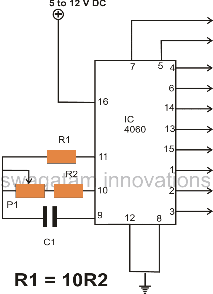
Parts List
R1 = 2M2
P1 = 1M pot
R2 = 100K
C1 = 1uF/25V
Understanding Pinout Functions of IC 4060
Let’s try to understand the pin outs of the IC 4060 in simple terms:
Referring to the figure we see that the only input pinouts which are required to be configured with external parts are pin # 9, 10, 11, and 12.
All the remaining pinouts are the output pins of the IC, except pin#16 and pin#8 which are Vcc (+) and the Vss (-) supply pinouts respectively.
The output pinouts are 7, 5, 4, 6, 14, 13, 15, 1, 2, 3 which are assigned for producing the ON/OFF time delays, or the clock signal outputs, or the oscillations, or the frequency at different levels depending on the values of the resistor Rt and the capacitor Ct on pin#10/9 of the IC respectively.
Pin #7 generates the highest value of frequency, while pin #3 produces the least.
For example, suppose the resistor/capacitor values at pin#9/10 causes pin # 7 to generate a frequency of 1MHz, then pin #5 would generate a frequency of 500 Khz, pin # 4 would generate 250 Khz, pin #6 would generate 125KHz, pin #14 would generate 62.5 KHz and so on.
As you may notice the frequency goes on becoming half in proportion, and this happens with the pinout order of 7, 5, 4, 6, 14, 13, 15, 1, 2, 3, wherein pin#7 produces the highest frequency, while pin#3 the minimum.
As mentioned earlier, the above frequency or oscillations can be initiated or setup by connecting a few passive components at pin#9, 10 and 11 of the IC as shown in the figure, it’s that simple.
How to Adjustable Timing
The variable resistor Rt could be replaced with a potentiometer at pin#10 of the IC 4060 to get an adjustable frequency output across the mentioned output pins of the IC. Alternatively, the capacitor Ct value may also be altered for changing the frequency of the IC.
How to Connect the Reset Pin
Pin #12 is the reset input and should always be grounded or connected to the negative supply.
A positive supply pulse to this input will reset the oscillations or revert the IC so that it begins counting or oscillating from the zero, causing all the outputs to switch to zero logic.
How to Achieve an Automatic Power Switch ON Reset
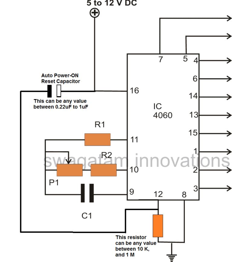
Enabling an automatic power switch ON resetting of a timer IC such as IC 4060 becomes crucial in order to initiate the IC clock, and counting process from zero.
If an auto reset facility is not included, the IC could exhibit a random or a haphazard initialization of its counting process, which may not be from the zero or start, rather from any intermediate level.
Therefore to ensure an automatic resetting for the IC, we must include an RC network with the reset pinout ofthe IC as I have explained below:
Instead of connecting the pin#12 directly to ground line, connect it through a high value resistor such as a 100K.
Then attach a small value capacitor from positive to pin#12, the value could be anywhere from 0.33uF to 1uF.
That's it, now your IC 4060 timer circuit is enabled with an auto reset feature, and will always initiate with a stable start, from zero.
Enabling a Manual Reset Action
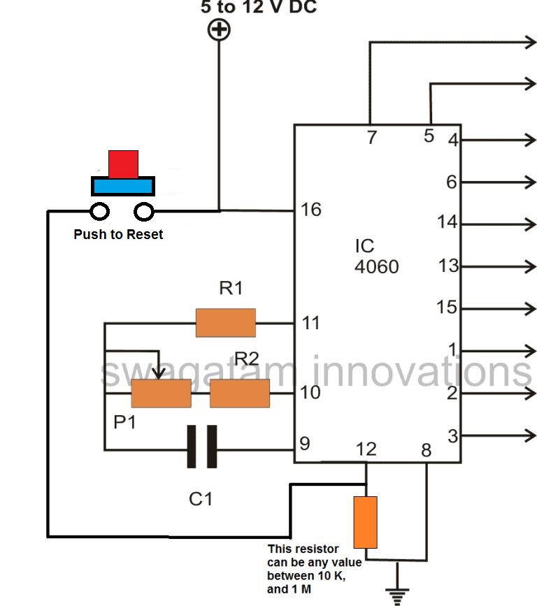
To achieve a manual resetting facility in any IC 4060 circuit, you can simply replace the capacitor with a push button, as shown above.
Pressing this button anytime during the counting process of the IC, will quickly reset the IC to zero, so that the counting can start afresh from zero.
Calculating the Timing RC Component Values
The image below shows the magnified section of the IC containing the oscillator pin#9, 10, 11.
The Rt and Ct are the main timing components which are actually responsible for determining the various delay intervals or frequencies across the IC outputs.
How the Oscillator Works
Referring the the below show internal configuration, we can see that the timing parts Rt, and Ct are configured around a NAND gate and NOT gate, in a classic logic astable stage.
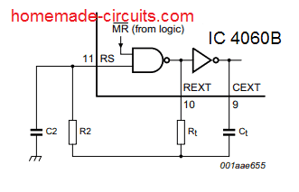
The standard formula for calculating the Rt and Ct values is:
f(osc) = 1 / 2.3 x Rt x Ct
2.3 is a constant as per the ICs internal configuration.
The oscillator will essentially work normally only when the selected values satisfy the conditions:
Rt << R2 and R2 x C2 << Rt x Ct.
R2 is positioned to reduce the frequency effect of the forward voltage over the input protection diodes.
C2 depicts the stray capacitance and is supposed to be minimal for enabling greater accuracy of the output time intervals.
For this, Ct must be relatively larger than C2, the larger the better.
Rt must be also a rather large value to negate the internal LOCMOS resistance, which appears in series with Rt internally.
Its typically value is around is 500 Ω at VDD = 5 V, 300 Ω at VDD = 10 V and 200 Ω at VDD = 15 V.
In order ensure a proper oscillatory action the most recommended values of the above mentioned timing parts must be configured as per the following conditions:
- Ct ≥ 100 pF, up to any workable value,
- 10 kΩ ≤ Rt ≤ 1 MΩ.
Supply Pins
Pin #16 is the positive of the IC and pin #8 is the negative supply input of the IC.
Using IC 4060 with Crystal Oscillator
Although the IC 4060 itself is fairly accurate with its frequency of oscillation and delay periods, this can be further enhanced using an externally crystal device with the IC.
A crystal based oscillator will enable locking of the frequency to the predetermined value, and prevent any form drifting from the intended value.
The following diagram shows how to connect a crystal device with the IC 4060 for achieving a constant and accurate frequency output:
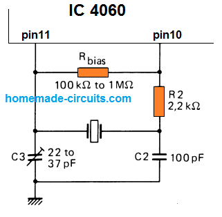
As we can see in the above figure, only the pin11 and pin10 are used for the integrating the crystal with the IC. R2 is used for initiating the crystal oscillations by supplying the required voltage pulses to the crystal.
C3 and C2 enable the crystal to reach its rated resonance frequency. C3 can be tweaked to change this resonance value of the crystal slightly, and therefore the output frequency of the IC 4060 accordingly.



Questions & Answers
Good morning sir,
Before came across this article I've spent few hrs. of my life and a lot of anxiety,headache,frustration…..
Actually I had made a JHULA for Shree Krishna in the occasion of Happy Janmashtami, last year.Where I have used 4060 and 4017 circuitry for continuing and resting the Jhula. There is a mistake in your ckt. also, where the pin 8 of ic 4060 is not grounded.
This year, when I am checking the 4060 ckt. only, on project board,it's working fine without grounding pin 8 but when soldering on pcb it's not working(it may be for the long thread of project board working as a ground.),I need your explanation.
You are heartily requested to spend a few valuable minutes for me.
And a final request,try to publish a few words for newbies….like,
1)Check the diagram on project board.
2)Pay attention/be careful when soldering on simple pcb.
3)When soldering the ic. base too much attention is needed.
4)After soldering, carefully remove the soldering paste/acid with a small piece of cotton.
4)Not to give hope but to check the circuit and solderings again and again;
Electronics needs 100% accuracy.(as a newbie I learned these in practical way). I think you may add more words as a guide lines.
Thanking you,
K. Kausik
Hello Kaushik, which circuit of mine has the mentioned mistake, can you please show me? pin#8 has to be mandatory connected to ground for 4060 and 4017 ICs…if it's working without connecting that may be temporary and sooner or later it will begin malfunctioning and also damage the IC.
yes checking and troubleshooting without losing patience is the key to success in electronics…but the newbies often don;t understand this and start blaming the circuit itself instead of finding the fault in his construction, or doing some simple tweaks which may be accidentally missed in the original design…
If possible I'll surely post a separate article explaining all those points, thanks for suggesting this.
dear sir i need a timer for incubator horizontal tray setup so please help me
i want one timer circuit for three hour delay
in my incubator i want to turn the egg every three hour so please help me sir
you can select one of these as per your requirement
https://www.homemade-circuits.com/?s=incubator
hi dear friend
i reading this article, its very usefull for me.thank u.
really i want to design an astable multivibrator with adjustable on-off time independently.
my on time variable between 2micro second ~1500 micro
and my off time between 10 micro ~750micro.
if you can please tell me :what is the best and accurate and simple way in your opinion
yours sincerely
mohammad
Hi Mohammad, I think a transistor astable should be able to fulfill your requirement, more info can be found here:
https://www.homemade-circuits.com/transistor-astable-multivibrator-amv-calculator
Hey Mohammed, to achieve that, you’ll need to build the 555 ic astable and use two different variable resistors as R1 and R2 to control the mark-to-space ratio or ON and OFF time as you mentioned.
R1 for ON and R2 for OFF
You can find an example design under this post
https://www.homemade-circuits.com/ic-555-oscillator-alarm-and-siren-circuits/#Variable_PWM_Oscillator_Circuits_using_IC_555
Please Sir, reply me.
this is Ankush bhosle
I have made anAC detector….if the magnetic field is there then it’s blinking LEd lights,it’s working good,but if I take away from magnetic field then the LEd light is glowing continuously
Hi Ankush it is a bad circuit and unreliable. If you want a reliable an perfect circuit, build the following one:
https://www.homemade-circuits.com/how-to-make-non-contact-ac-mains-phase/
Thankyou for this clear and informative article. I am buiding a clone of an “Olegtron 4060” , which is a little musical noise maker. This article has made the order of the pinouts a lot easier to follow than the data sheet in my opinion. Thanks again.
I am glad the post helped you with the required information. Wish you all the best!
Hello Swag,for the cd4060 drived by crystal oscillator input what xtal can i put on P11 P10 to obtain 200khz?
Thank you
Hi Mathieu, yo an try a 200 kHz crystal
Hello Swag,yes but for the output of the cd4060 for 200KHZ what can i put on p11 and p10 like quartz?
thank you
Hello Mathieu, I think it’s better to go as suggested by the datasheet of the IC, I do not have precise idea regarding crystal working, so I would suggest you to follow the same diagram which is explained in the above article.
Hi Swag! why when a touch the voltage regulator and the positive intput of the CD 4060 its value varie in output? ex: Q5 output for (221KHZ without contact)and (250 KHZ with contact on reg 9vdc)
thank you!
Hi Mathieu, try adding a 10uF capacitor right across the +/- terminals of the IC and check the response…
Hi Swag, can you tell me why i have frequency output on pin 1 to 4 of my cd4060 with a 8MHZ crystal oscillator and irregular frequency on the other pins? i have tried with the 10µf on pin 16 to ground 8! no differences! my voltage regulator is a 7809!
Thank you
Hi Mathieu,
please read the IC description in the above article, you will come to know that except pin9,10,11,16,12,8…all the other pins are outputs and have incremental frequency rates, with pin#7 having the highest frequency and pin#3 the lowest.
Hi Swag! yes the divisions are from pin 1 to 7 and pin 13 to pin 15!
the problem is that i have irregular frequency on pin 5,6 and 7!
Hi Mathieu, do you mean they are not rectangular in shape? what is the supply voltage you have used for the IC? Please try 12V or 15V and check the response!
Nice stuff.
Thanks for this great article, you said for 1hr, i should pick pin#3, for 3 hrs and 6hrs, please sir what can I do.
Pin3 has the maximum delay range compared to the other output pins of the IC, therefore I always recommend pin3 as the output for any 4060 based timer circuit, so that maximum delay can be achieved using relatively smaller capacitors. For 3 and 6 hours also you can use pin3 but with higher C1 value.
can i use crystal above 10Mhz, what will be happen if i will use 32Mhz crytal what will be effect on out put frequency,
Hello Swag so on pin 10 15pf and on pin 11? Between pins 10 11,do i put a 1mhom resistor or 100k resistor?
thank you
Hello mathieu, you can use 1M for Rbias, 15pF for C2, and 33pF trimmer for C3
Hi Swag, after your opinion on the schematic i have changed the 33pf with an ajustable,the output frequency is 5,5hz instead of 1953khz(on pin 1 for 8mhz quartz)!can it be the IC or maybe a component?Thank you!
Hi mathieu, please try adjusting the trimmer and check on pin #7 of the IC.
Hello,Swagatam.Can I use 15 megaohms for Rbias and 510 kiloohms for R2 for working with 32 768 Hz quartz oscilator?What should be capacitances in this case?
Hello V.Maslaroff, I don’t think 15M can be used for the Rbias, since the maximum recommended value is 1 M.
Hellow again.A schematic diagram in a russian magazine is given with Rbias 15 megaohms and R2 510 kiloohms,and some other capacitors.I had already realised it,and it works fine;I examinated it by the oscilloscope.The only trouble is that it doesn`t react to the trimmer for adjusting;but it is not needed since the 32,768 hertzs are exact.
My other question for you is about the RC-oscillation.To get 5120 hertzs I chose 1 nanofarad capacitor,85 kiloohms for Rt(obtained by 56 resistor and 47 potenciometer),220 kiloohms for R2 and 10 picofarads for C2,intending to get 10 hertzs at Q9(pin 13).Is this fine and am I right about the output?
Thanks for the update. If the values are working for you, then it should be fine.
You can use the given frequency formula to calculate the output frequency.
Just make sure to convert the capacitor value in Farads.
hi,
iam trying to make an oscillator using the CD4060BE RIPPEL COUNTER OSSICILLATOR, iam using a CRYSTAL 2457.6kilo hertz for frequency controle and osscillation, can you suggest the proper circuit between pin 10,11, and earth ,or otherwise , with this crystal.thanks
Hi, the example design is given at the end of the post
so i’d like to build an automatic lamp timer using the IC4060. Anyone wanna help out on how i can connect the pins? THANKS <3
Excellent tutorial
Hi there, hope you can help me as soon as possible. currently i am doing a project on leveling water pump with timer using timer and using ic 4060 and i copied your schematic and you tell me how to calculate real time similar to the outside. hope you can help me to finish it . thank you very much
Hello, the Rt Ct formula can be confusing and time consuming. The easy way would be to check the timing practically by using any arbitrarily selected resistor and capacitor, and then estimate the other desired timings through cross multiplication.
For example, use 100K resistor on pin#10 (in place of R2/P1). Use 0.1uF for C1, switch ON power, and check after how many seconds the output at pin#3 becomes high. Once you get this, use this as the sample timing and get the desired timing through the following cross multiplication:
Sample Delay / Desired Delay = Selected Resistor at pin#10 / Unknown Resistor
or you can find the capacitor value for the desired time output using the following formula:
Sample Delay / Desired Delay = Selected Capacitor at pin#9 / Unknown capacitor
hi swagatam do you have facebook or instagram or any social network i really need your help on this topic. i am in college and my assignment due is next week i really need your help in depth about pump using ic 4060 . help me please
please reply me soon
Hi Johnny, sorry that may not be possible due to lack of time. You can ask your questions here through comment, if possible I will try to solve it for you.
I am looking to build a external fan controller circuit with a speed control (via pot) and user adjustable timer (30 min-4 hours). Suggestions?
Please provide fan specifications, I will try to figure out
Pls sir what does Ct ¤ 100pf and 10k ¤ Rt¤ 1M means
Rt, Ct are the resistor and capacitor at pin10 and pin9 of the IC which determine the output frequency of the circuit
Hello Sir ,why Rbias is used?
Hello Sam, it is required for the proper functioning of the IC internal gates with the crystal.
Hi Swag, Wonderful website….. well done. I am building a switch which will turn off my immersion (2 kW) 24 hours after ‘nobody home detection’
It must have the following attributes :
* Power ON from start and start counting down from 24 hrs to zero
* Reset to 24 hours if detection during interval
* Detection will be by PIR detector
Question: Should the output (high) from the PIR go to pin 16 ?
** I will also then build one using an Arduino as it will require other attributes such as Time clock, Go on outside time if OFF for more than 48 hrs if detection occurs
Thanks Jonny A
Thank you Jonny, Glad you liked the website.
To reset the 4060 through a PIR, you must connect the PIR output to pin#12 of the IC.
Before this make sure the pin#12 is connected to the ground through a resistor. This resistor value can be anything between 10K and 1M.
Also, the PIR output voltage must be higher than 3V for proper resetting of the 4060 IC
Thanks
Hi Swag
As the output pins of the 4060 go positive, do they remain positive as the counting progresses. I am asking this because I read somewhere that the output of all the pins resembles a binary number between 0 to 2>14
Hi Jonny,
The output will oscillate ON/OFf with 50% duty cycle depending of the values of the parts at pin#9 and pin#10. For example, if you select pin#3 as the output, it will initiate the timing with a logic zero, then become logic 1 after a predetermined delay, then again turn zero after the same delay and keep repeating this ON/OFF cycle.
To ensure that once the output turns positive it remains latched to positive, you may have to connect a 1N4148 diode between pin#3 and pin#11. Cathode goes to pin#11.
Hi Swagatam!
I have a cd4060 circuit that I would like to turn on with an IR transmitter(38khz). I am using a 34838 IR receiver IC. I would like the cd4060 circuit be on for a determined time and then shut off until the next burst from the transmitter. The circuit will be powered by a 6v-4lr44 battery.Thanks!
Hi Norman,
It seems you want the IC 4060 to work like a monostable. Sorry, I have no idea how a 4060 can be used like a monostable and triggered by an external signal.
Morning Sirji, I was referring to Automatic Power Switch ON Reset (name as shown in the article here above) at this page.
This ckt here uses single CD4060 alone for the Timer! The diagram before (above) this ckt gives C1= 1uF but no such value is shown right in the required ckt that I have decided to use.
Even if we take R1=2M2, R2=100K then we still have C1 value as unknown. If you please give me a generalised value to take for C1, it would help me a lot and the rest of the precise switching time can be set using the Pot.
I had to change the comment page because the page (there) was saying “Some of the field values are invalid.” And the comment was refused for uploading! Sorry for the problem!
Awaiting your kind advise!
Thank you again!!
Hi Maddy,

In the following diagram, the timing capacitor value will need to be experimented, but a starting value can be a 1uF capacitor non-polar type.
Can it have C1=1uF and rest of the variation be done with the Pot! Because I don’t have a bunch of Non-polar capacitors and getting a score of values from the market just for testing is Out of bounds for me!
Please advise! Thanks again Sirji!!
Yes, the C1 can be a fixed 1uF capacitor, and the timing adjustment can be done using the pot, no issues. Make sure the 1uF is a non-polar capacitor…
Good evening Sirji!!
Considering any Timer ckt, be it discussed here or anywhere else on the website, one question arises!! Can a single Timer ckt be used to operate two similar Relays simultaneously. What changes need to be introduced in the Timer ckt to enable it for that purpose? Basically, I need to control different areas of a ckt using same Relay operating at equal Time control. I have two DPDT relays but I need to control three points in a ckt. So you can understand why I need this explanation.
Please advise!! Thanks again Sirji !!
Good Morning Maddy,
If you are using a transistor driver to operate the relay, then you can add additional number of parallel relays with that transistor, and operate them simultaneously.
Good noon Sirji. Sorry for late response! I thought my question was lost due to unknown reasons. Now do you mean to say that by introducing a transistor between Timer and Relay, like the one used in 555 Timer, we can use same transistor to operate two relays in parallel combination? If possible can you please refer me to any ckt diagram present on this site that employs same idea? That would be more easy to absorb Please advise!!
Thank you!!
Good noon Maddy, Yes, due to a serious technical glitch I had to restore my site through the previous day’s backup and so all the recent comments were lost! sorry about that!
You are right, using a single driver transistor and a single 1N4007 diode between its collector and the positive supply, you can add any desired number of relay COILs in parallel with this diode.
Just make sure that the total relay coil current does not exceed the input supply DC ratting and the transistor’s current rating.
I hope you understood the wiring, let me know if you did not.
Good evening Sirji!
Do we any such diagram which employs this particular idea for given purpose? That would directly facilitate understanding and copying the arrangement for me!!
Thank you Sirji!!
Good evening Maddy, do you want to see the diagram of the transistor relay driver? Then you can refer to the following post:
https://www.homemade-circuits.com/how-to-make-relay-driver-stage-in/
You can connect additional number of relay coils in parallel with the existing relay coil….
A very good evening Sirji,
there is a mistake in the diagram above in Auto Power On Reset section. Actually the image says that the polarised capacitor value can be anything from 0.22uF to 1uF. But the description just below the image says it can be anything from 0.33uF to 1uF. Please check it and clarify which one to take as correct.
And sorry if I have posted my question two times. My Internet was running little slow so I had to disconnect and then reconnect during uploading and I thought that my question went Foooo…
Thank you!!
Maddy, if you are referring to the power reset capacitor, that capacitor can be any value between 0.1uF and 1uF, it is not critical… because the value only decides how long it takes for the IC to be reset and ready for use….0.1uF to 1uF just delays things in milliseconds, so no big deal…it doesn’t matter whether the reset delay is 10ms or 100ms…it gets over in a blink.
The reset power ON capacitor can be polarized or non-polar, does not matter again.
Sorry again Sirji !!
https://www.homemade-circuits.com/how-to-make-simple-versatile-timer/
In all the circuit diagrams at this link you have used a non polar capacitor of 0.1uF.
Now this becomes extremely confusing for a hobbyist like me. Polar or non.polar. And which value to be taken.
Sorry again.
And Thank you.
Maddy, there’s nothing to be confused. In the previous comments I have mentioned that this capacitor (@pin#9 of 4060) is the timing capacitor, which can vary depending upon how much max delay range you need at the output. So with 0.1uF the range will be much reduced and with 1uF it might increase 10 folds.
The important thing is that this capacitor must be a non-polar type, which I have repeatedly mentioned in all my previous comments. Please let me know where the confused arise, I will try to solve it…