The circuit discussed in this article is of a non-contact mains AC field detector which displays the presence of a mains AC field from a distance of more an 6 inches.
Locating Fault in AC Lines without Physical Contact
The circuit can be used for locating faults in house wiring without the need of making physical contact with the inner conductor of the wire and becomes useful in locating the breaks in a wire by pin pointing the area where the AC mains may be blocked due to a breakage.
The circuit is basically high gain non inverting amplifier which is configured using a few opamps and a few other inexpensive passive electronic components.
Just a couple of opamps have been incorporated here from the IC 324 for the required operations.
Design Description
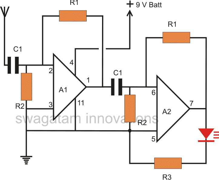
Looking at the figure we notice the following things:
The non-inverting input of the IC is grounded making the sensitivity of the configuration to the maximum.
Similarly a feed back loop created by connecting the output of the opamps to the inverting input helps to increase the gain of the set up many folds.
The input is applied to the inverting input 2 of the IC through a blocking capacitor.
The signals entering via the antenna is quickly picked up by the opamp inverting input and sent to the
preceding circuit for the required processing and amplification.
It may be interesting to note that the sensitivity of the design can be simply varied by changing the value of the feedback resistor R1, for maximum sensiticity this resistor can be omitted.
However this can make the circuit a bit unstable and might provide false results.
Second Series opamp Amplifier Function
The next stage includes another identical amplifier which is just the repetition of the previous input stage.
This stage has been included in order to make the response of the circuit instant and so that the circuit is able to pick even the slightest of RF or the AC field within a certain range.
In case the circuit is intended to be used for detecting mains phase only at touching proximity, the sensitivity may be reduced to the required levels or the second stage may be excluded from the design.
The LED connected at the output is used for displaying the presence of the AC field; an illuminated LED identifies the presence of the field while no light from it provides the opposite conclusion.
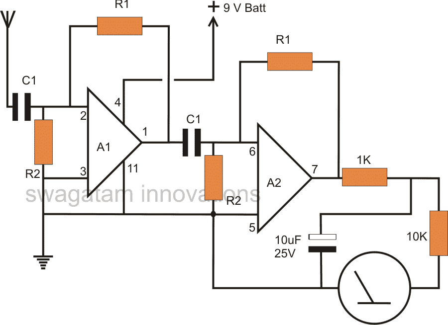
By connecting a 1V FSD moving coil meter at the output, the device can be used to detect and measure the average strength of the AC mains present in that particular vicinity.
Parts List
- R1 = 2M2,
- R2 = 100K,
- R3 = 1K,
- C1 = 0.01uF
- A1, A2 = IC 324
Video Clip:
Feedback from one of the avid followers of this website:
Am a civil engineer by profession based in Bangalore. Am in the construction industry for the last 20 yrs, have a manufacturing unit for modular kitchens.
Here is my requirement to automate the dust collector on or off for three different CNC based machines.
The company does not allow me to physically tap into any electrical but allows me to use a non contact voltage detector.
So I need to process the output of the non-contact voltage detector through IC LM324 and trigger a 12v relay which will switch the dust collector on or off.
The dust collector load is 7.5 hp 3 phase.
I would like to sense the voltage of the conveyor motor of the machine which is 3 phase Ac, 50 htz, 4amp. When this conveyor motor comes alive I would like the dust collector to come on and vice versa.
I have attached the photo of the motor and the specifications in my next mail. This motor has a MPCB which has a 24v control voltage triggering the mpcb. I intend to have a MPCB for my dust collector motor as well.
Kindly let me know if you need further specifications/requirements for the same.
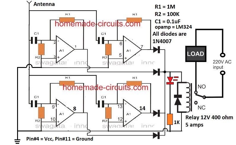
Circuit Diagram
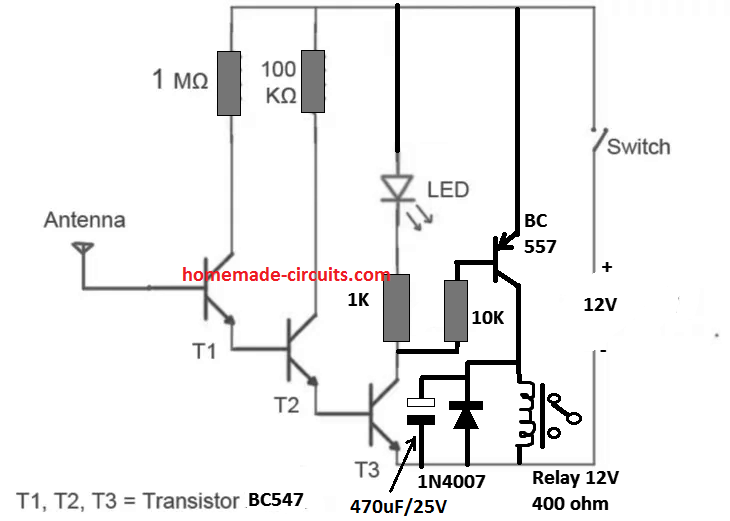
The complete circuit for the above application can be witnessed in the following diagram.
The first design is a relatively easier one using only transistors. The second one is using 4 opamps of LM324. Both are designed to activate a relay in response to an AC phase detection, non contact.
Another Very Simple Mains AC Hum Detector Circuit using IC 4011
The hum receiver is made up of a single COS/MOS IC consisting four NAND - gates (CD 4011). The four gates are connected in series to form signal amplifier like configuration.
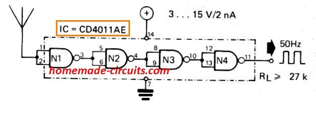
The first gate (N1) detects the 220 V or 120 V AC hum radiated by the mains grid electrical line. You must take care not to keep the NAND gate inputs far away from various other sources of RF interference su ch as amplifier outputs, etc. A copper wire with a length of 2 to 3 cm will be adequate to serve like an antenna for picking up the 50 Hz or 60 Hz hum and to process the signal into a correspnding level of square wave output.
The output may show a risetime of about 20 ns at the output of gate N4. Based on the circumstances, one or two gates can often be eliminated. The current consumption of the complete CD 4011 IC is extremely minimal hence a 4.5 V battery employed as the power supply may be equivalent to almost the normal shelf life of th battery.
AC Mains Wiring Finder
The next circuit describes a straightforward way of finding conductors which carry alternating current or AC mains. A 100mH pick-up coil with a which is utilized as a detector coil.
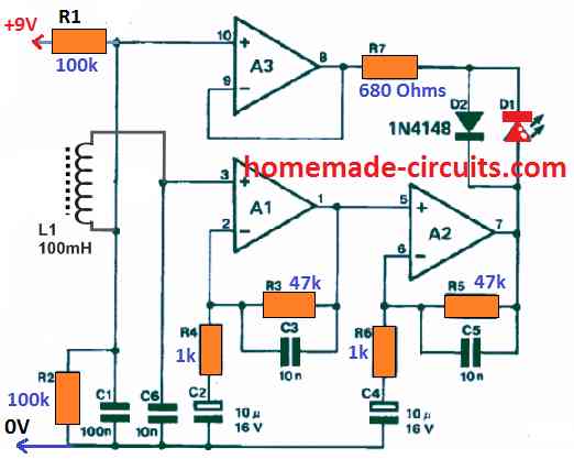
A current-carrying conductor generates a magnetic field and holds a minute voltage in L1, which is amplified through opamps A1 and A2.
Capacitors C2 to C5 occupy a value that makes sure maximum amplification in A1 and A2 with signals about 50 Hz. Throughout the positive half-waves of the AC network, D1 stays lit.
AC Phase Detector with Buzzer
Refer to the schematic diagram below. Via C1, the probe plate is linked to Q2, which is a very high-impedance amplifier. Although C1 is not required for the circuit's efficient functioning, it is important for its safety. C1 will prevent any deadly voltages from being unintentionally attached to the probe. After Q2 amplifies the input AC signal, it travels via C2 and D1 to produce a negative voltage clamp.
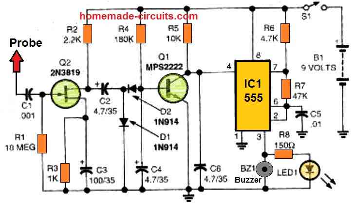
D2 rectifies the clamp output such that only negative voltages impact Q2. R4 typically switches on that transistor. However, while the clamp is active, Q2 switches off. Pin 4 (the reset line) of IC1 is freed when Q2 is turned off. R5 provides a positive voltage, allowing IC1 to start oscillating. A piezoelectric buzzer and an LED are driven by the output of IC1 (pin 3). R8 controls the current flowing to LED1. R6, R7, and C5 determine the frequency at which I C1 oscillates.
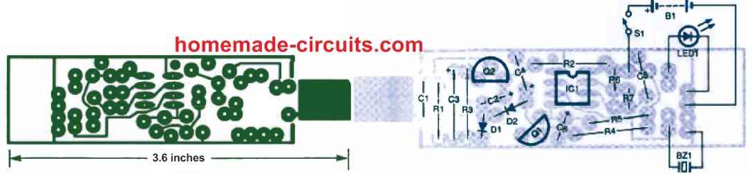
Install the PC board into the enclosure to ensure that no parts interfere with BZ1, S1, LED1, or B1. With the help of the below overlay diagram as a reference, hook up from those elements to the PC board. While wiring BZ1, the black lead, including the negative terminal of B1 and the cathode of LED, is connected to the common ground.
Testing
Hookup the Electrostatic Voltage Probe to a 9-volt battery. LED1 should glow momentarily when S1 is pressed, and BZ1 would beep while C4 charges. If this occurs, the circuit is most likely in good functioning order. The last testing is to place an extension cable close to the probe which is inserted into a wall socket with S1 is closed. The cable must be positioned against the flat side of the probe; aiming the probe end towards a AC cable will yield no results.
The buzzer must sound consistently and the LED must glow. Disconnect the extension cord; LED1 and BZ1 too should be turned off. The Electrostatic AC phase sensor is operating effectively if it satisfies this test. Loop the wires from B1, S1, and LED1 around the edge of the PCB between the board and the box before mounting it in the box.
Between B1 and the PC board, place a waste bit of plastic, cardboard, or a clean PCB with no copper on it. Close the case and cover the probe with a section of heatsink piping where it emerges from the container. To ensure that no bare PCB metal is visible, trim the tubing slightly longer than the probe itself. Walking across your home and checking several extension AC cables would be an excellent test. It's worth noting that you'll be able to tell exactly which side of a parallel-conductor lamp cable has the LIVE wire. The voltage probe might buzz occasionally as you move the device along the AC cord, in case the cord is made of twisted pairs.
Test Results
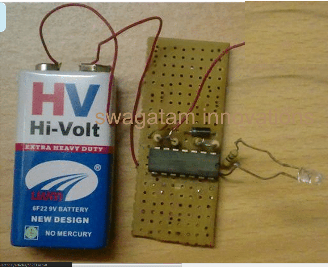
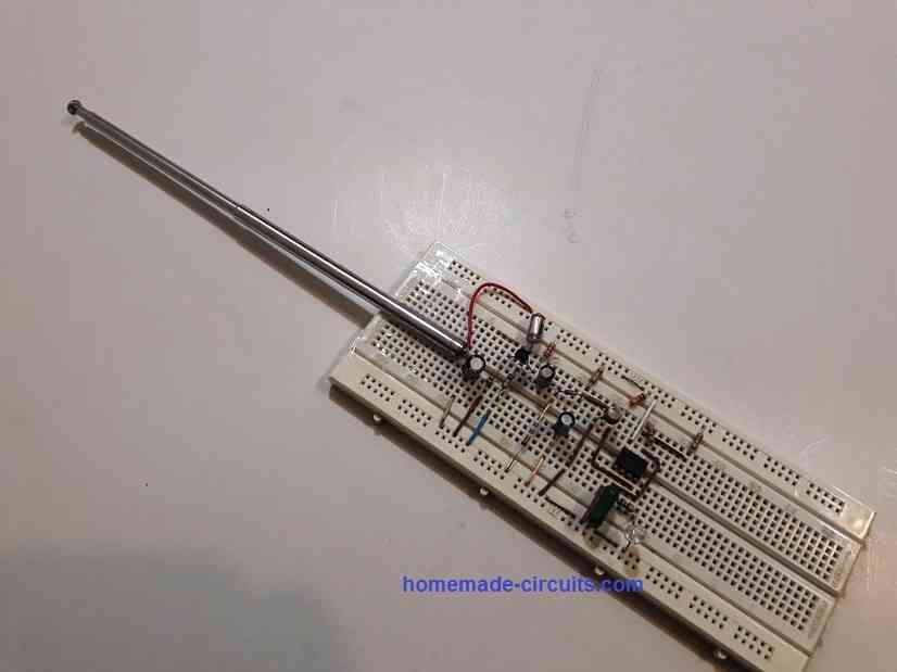
The above circuit was successfully built and tested by Mr. Ali, who is a dedicated electronic enthusiast and a regular visitor of this website.
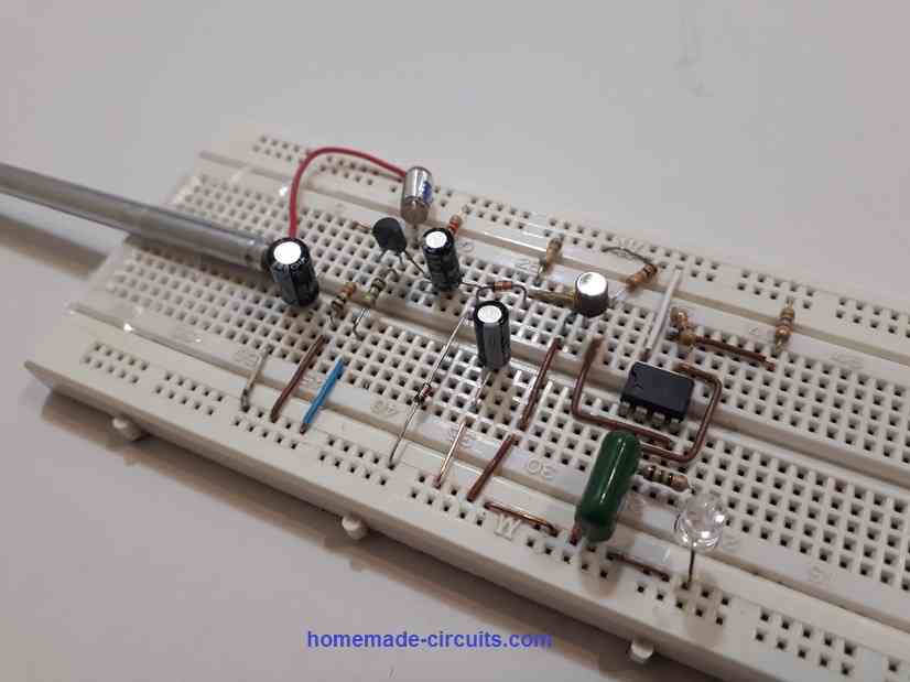
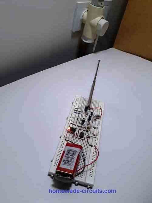
The following wonderful images and the video test result was contributed by Mr Ali, for our viewing pleasure:
Now, to answer the question asked in the video by Mr. Ali regarding why the sensitivity of the circuit was different from different angles is because the radiation pattern of the AC mains 50 Hz or 60 Hz is different at different angles.
This might depend on the inductors or the wires arranged in different patterns inside an electrical device or an electrical board which might cause the electrical frequency to be more dense and powerful at certain angles compared to the other angles.
To reduce the sensitivity of the circuit, you can simply reduce the length of the antenna.


Questions & Answers
Hi Mr. Swagatam;
Is there any circuit that we can use it to detect the not ac but dc voltage.
Thanks
Hi Suat,
It is not possible to detect DC without making a physical contact, a non-contact system might not be feasible.
Hello sir, Can I use this for detect current carrying conductor inside a concert wall??
Hi Kushani, yes you can try the sbove circuit, if the current to be detected is an AC.
Dear Sir Swagatam: How may I to set the gain (sensitivity) of the 2N3819 with a potentiometer? (IC555 based circuit) The circuit is very sensible, and I want to set it with a potentiometer! Thank you.
Hi John,
I think you can adjust the gain of the 2N3891 fet by changing the value of R1 10 meg resistor. You can reduce this value to reduce the sensitivity of the device.
Dear Sir Swagatam
Hello. Would you please tell me which of the 1st and last circuits would be able detect more inside the concrete? I want to do one of these two circuits. Meanwhile, is 2n2222 a good equivalent for mps2222 (IC555 based circuit)?
Thank you a lot Sir
Wish you all the best
Ali
Thank you Ali,
The first circuit is the one which I have tested and I found it to be very sensitive and should be easily able to detect AC mains wires under a concrete wall. Nevertheless you can also try the transistorized version and check if that works or not? Yes, 2N2222 and mps2222 are one and the same.
Thank you dear Sir Swagatam for your so soon answer which always makes me shy and glad too. I will try to do the transistorized version and will tell you the result.
Wish you all the best, kind man
Best regards
Ali
It’s my pleasure Ali, do let us know how the circuits work.
Dear Sir Swagatam
Hello. would you please tell me if the pin of the 2N3819 transistor that is connected to the 2.2 k resistor is drain or source?
Best wishes
Ali
Hi Ali, it is the drain of the FET which is connected with the 2.2k resistor in the last diagram. Also, you can replace the MPS2222 with a BC547.
Dear Sir Swagatam
Thank you very much for your kind response.
Best wishes
Ali
No problem Ali, I am happy to help!
Dear Sir Swagatam
I hope you are fine and healthy. During the past two days, I assembled three circuit diagrams of Non-contact line detectors, on breadboard. Neither the LM324 based circuit, nor the circuit composed of four BC547 transistors under the title “Non-Contact Mains Phase Detector” (linked below) were as sensitive as the 2N3819 FET based circuit. I will send pictures and a video of it to your Email. I must say that the length of telescopic antenna was about 20 cm. and when I reduced it to half, I should also reduced the distance to the mains socket in order to LED goes on.
Thank you so much for your very good site and your help as well.
wish you all the best
Ali
Dear Sir Swagatam
Thank you so very much for encouraging me and for uploading the video and pictures on your site. I also thank you very much for your endless and useful help. I will never ever forget your kindness dear Swagatam.
Wish you joy and health. God bless you lovely man.
All the best
Ali
Thank you Dear Ali,
It’s my great pleasure! Wish you all the best, and God bless you!
Thank you Dear Ali,
Great! So according to you the FET based design is the most sensitive one! I appreciate your efforts and glad you could build it successfully.
I saw the video and the images you sent me through email. They are all so wonderful.
I have uploaded them in the above article, you can check them out.
Many thanks for your contribution. Please keep up the good work 🙂
Is anyone selling reliable non-contact voltage detectors that drive a relay in the marketplace? I have an application for many of these device and do not want to have to build them.
thanx sir, that’s what exactly i need,
sir, can i use lower or higher than 400 ohms if ever i don’t have this exact value.thanx
You can welcome Dennis, which circuit are you referring to?
hi sir, the circuit that uses only one transistor bc 557,
btw sir,i have relay of 397 ohms,i just tested now. thanx for clarifying.
sir can i ask my question here,out from topic ,just curiuos about what you told me before.
” you said for lead acid battery,charging current should be 1/10th of battery capacity,while li-ion needs 50% of its capacity,why is that,
also, are different types of batteries vary charging current.thanx sir
Hi Dennis, 397 ohm relay is same as 400 ohm relay and will work.
The charging current of a battery is determined by its internal working characteristics, and can be checked from the manufacturer’s datasheet. I have provided the ideal charging rates for ensuring a long life for the battery.
ok sir
thanx for clarification about battery and for relay
No Problem Dennis!
Hi Sir Swagatam
Hello. I want to do your first circuit in order to help me to detect where and how deep is lying the main’s line wire when drilling the wall in order to prevent drilling the wire which could be dangerous. You are kindly requested to tell me how deep it detects the line wire and how accurate is it in determining the proper place of the wire.
Thank you very much Sir
Best regards
Mike
Hi Mike, the sensitivity of the circuit will actually depend on the antenna length. For a 6 inches antenna, the circuit will be able to detect up to 4 inches deep inside a concrete. The detection accuracy will also depend on the antenna, for longer the accuracy will decrease, this will need to experimented to find the optimal length of the antenna wire.
The circuit will work only with a battery, preferably a 9 V battery.
Hello Sir engineer Swagatam
Thank you for your detailed response. Do you think that a telescopic antenna would be good for that?
Wish you the best; dear Swagatam
Best regards
Mike
Thank you Mike, actually any piece of metal will work as the antenna, but a telescopic antenna might give better results due to its larger diameter.
Thank you very much for your response, Sir Swagatam. You pointed out an important issue: the thickness of of the antenna. you are really a very good man. Never forget you kindness.
Best regards
wish you all the best
Mike
You are most welcome Mike, I am always happy to help!
Hello swag, I designed 27Mhz FM transmitter. but not getting constant frequency, can you please suggest me proper circuit, with crystal oscillator.or any IC available in market for FM.
Hello Rakesh.
are you referring to the following circuit:
https://www.homemade-circuits.com/simple-walkie-talkie-circuit/
If possible I’ll try to publish another one but it’s 10km range system.
Hi Swag,
I notice that this circuit uses a 324 IC (LM324). This is a Quad Ampop. Can I use a Dual Ampop?
Best Regards.
NA
Hi Neilio,
In my prototype I had used LM324 IC, but any other dual opamp should also work, such as LM358 etc
Hi Swag,
Post this comment in a wrong circuit (in Spectrum Analyzer).
What are de specifications of the antenna? A Wire? Size? Type?
Best Regards.
Nélio Abreu
Hi Neilio, No problems!
The antenna is simply a 3 to 6 inches long flexible wire, any thin flexible wire will do.
Please see the video to get a correct idea of the wire length and type
Hi Swagatam, I tried to make this project but I cant seem to make it work. Can you please upload a schematic (with the IC symbols etc). Thanks in advance
OK, no problem.
560 ohms is OK, but you have shown 560 K ohms in the image which is incorrect.
AC/DC adapter will not work, you'll have to use a battery.
most probably your circuit is not working because of the adapter….
I will try it on a perf board and let you know if anything is wrong.
Regarding the 1k resistors, I labelled them wrong. They should be 100k as indicated in your parts list (R2).
About the 560ohm resistor, i calculated it with an app (I use ElectroDroid app from play store) and determined that thats what i need to get around 10mA across the LED from a 7.2v supply (please let me know if this is incorrect)
Last, i was using a wall wart (AC-DC adapter) as my power supply. Just had a thought if this could interfere with the circuit considering how sensistive it is. Will try a 9v battery.
….by the way the 1K resistors indicated in your breadboard image are all 100k, and you have used 560k as the limiting resistor for the LED, not sure from where you got this value that's huge and incorrect
I am afraid breadboarding probably will not work for this design since the circuit is very sensitive and the long wires on the breadboard might upset it.
please refer to the prototype image which was successfully built by me, see how the components are placed so compactly on the tiny PCB by soldering them.
it will need to be built exactly in this way
I have uploaded my breadboard photo (imgur.com/JQiVPKT).
As soon as i power up, the LED is dimly lit and when i touch the antenna with my hand, it goes off. And there is no change when I bring the antenna near an AC line.
Hi John, you just have follow the pin numbers of the IC as given in the diagram and assemble it exactly as is.
if you can tell me what's specifically happening with your circuit, I would try to troubleshoot it accordingly.
My led light comes on as soon as I plug in the battery