A step down transformer is a device which reduces a higher AC potential to a lower AC potential as per its winding ratio and specifications.
In this article we are going to discuss how to design and construct a basic step down transformer which are typically applied in mains-operated power supplies.
Introduction
This will likely help electronic hobbyists to develop and build their very own transformers based on their particular demands.
Within the next pages, a simplified layout method is presented in order to achieve satisfactorily developed transformers. On the other hand, the design process may be a subject of some experimentation.
The tables I have I have explained in this article trim computations short which help the designer to find the appropriate size of wire or even core lamination.
Exclusively pertinent data and calculations are supplied here to ensure that the designer is absolutely not baffled by unwanted details.
Here we will specifically discuss about transformers which possesses 2 or more winding of insulated copper wire around an iron core. These are: one primary winding and one or maybe more secondary winding.
Each winding is electrically isolated from the other however are magnetically connected by using a laminated iron core.
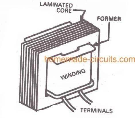
Small transformers possess a shell style structure, i.e. the winding are encircled by the core as demonstrated in Fig. 1.
The power supplied by the secondary is in fact transmitted from the primary, although at a voltage level dependent on the winding ratio of the a pair of winding.
Video Interpretation
Basic Transformer Design
As the initial phase towards the design of a transformer, the primary and secondary voltage evaluations and the secondary ampere rating has to be distinctly expressed.
After that determine the core content to be employed: ordinary steel stamping or cold rolled grain oriented (CRGO) stamping. CRGO features a greater allowable flux density and reduced losses.
The best possible cross-sectional part of the core is roughly assigned by:
Core Area: 1.152 x √(output voltage x output current) sq cm.
With regard to transformers having several secondaries, the sum of the the output volt-amp product of each winding needs to be considered.
The quantity of turns on the primary and secondary winding is determined using the formula for turns per volt ratio as:
Turns per volt = 1/ (4.44 x 10⁻⁴ frequency x core area x flux density)
Here, the frequency is usually 50Hz for Indian household mains source. The flux density could be considered as approximately 1.0 Weber/ sq. m. intended for ordinary steel stamping and approximately 1.3 Weber/ sq. m. for CRGO stamping.
Calculating Primary Winding
The current in the primary'winding is presented by the formula:
Primary Current = Sum of o/p Volt and o/p Amp divided by Primary Volts x efficiency
The efficiency of small transformers can deviate between 0.8 to 0.§6. A value of 0.87 works extremely well for regular transformers.
The appropriate wire size needs to be determined for the winding. The wire diameter is dependent upon the current rated for the winding and also the permitted current density of the wire.
The current density could be as tall as 233 amps/ sq. cm. in small transformers and as minimal as 155 amps/ sq. cm. in big ones.
Winding Data
| SWG | Max. current capacity (Amp) | Turns per sq. cm. |
|---|---|---|
| 10 | 16.60 | 8.7 |
| 11 | 13.638 | 10.4 |
| 12 | 10.961 | 12.1 |
| 13 | 8.579 | 13.6 |
| 14 | 6.487 | 21.5 |
| 15 | 5.254 | 26.8 |
| 16 | 4.151 | 35.2 |
| 17 | 3.178 | 45.4 |
| 18 | 2.538 | 57.3 |
| 19 | 2.013 | 72.3 |
| 20 | 1.313 | 106.0 |
| 21 | 1.0377 | 132.7 |
| 22 | 0.8183 | 167.4 |
| 23 | 0.6383 | 210.9 |
| 24 | 0.5046 | 265.9 |
| 25 | 0.4004 | 334.9 |
| 26 | 0.3284 | 415.0 |
| 27 | 0.2546 | 523.0 |
| 28 | 0.2024 | 659.0 |
| 29 | 0.1608 | 830.0 |
| 30 | 0.1558 | 881 |
| 31 | 0.1364 | 997 |
| 32 | 0.1182 | 1137 |
| 33 | 0.1014 | 1308 |
| 34 | 0.0858 | 1608 |
| 35 | 0.0715 | 1902 |
| 36 | 0.0586 | 2286 |
| 37 | 0.0469 | 2800 |
| 38 | 0.0366 | 3542 |
| 39 | 0.0284 | 4838 |
| 40 | 0.0225 | 5595 |
| 41 | 0.0197 | 6543 |
| 42 | 0.0144 | 9337 |
| 43 | 0.0113 | 11352 |
| 44 | 0.0090 | 14392 |
| 45 | 0.0079 | 17147 |
| 46 | 0.0059 | 20223 |
| 47 | 0.0047 | 25397 |
| 48 | 0.0037 | 31605 |
| 49 | 0.0029 | 40160 |
| 50 | 0.0010 | 81242 |
Typically, a value of 200 amps/ sq. cm. may be considered, according to which Table#1 is created. The amount of turns in the primary winding is presented by the formula:
Primary Turns = Turns per Volt x Primary Volts
The room consumed by the winding is determined by the insulation density, technique of winding and the wire diameter.
Table#1 provides the estimated values of the turns per square cm. through which we are able to calculate the window area consumed by the primary winding.
Primary winding Area = Primary turns / Turns per sq. cm from Table#1
Calculating Secondary Winding
Considering that we have the assumed secondary current rating, we are able to determine the wire size for the secondary winding simply by going through Table#1 directly.
The quantity of turns on the secondary is calculated in the identical method when it comes to primary, but around 3% excess turns should be included to reimburse for the internal drop of secondary winding voltage of the transformer, upon loading. Hence,
Secondary turns = 1.03 (turns per volt x secondary volts)
The window area necessary for secondary winding is identified from Table#2 as
Secondary window area = Secondary turns / Turns per sq. cm. (from Table#2 below)
Calculating Core size
The principal qualifying measure in picking the core could be the total window area of winding space accessible.
Total window area = Primary window area + sum of secondary window areas + space for former & insulation.
A little extra space is necessary to support the former and insulation in between winding. The specific quantity of extra area may differ, even though 30% could be considered to begin with although this may need to be customized later on.
Table Dimension of Transformer Stamping
Section 1
| Type No. | Tongue width (cm.) | Window area (sq. cm.) |
|---|---|---|
| 17 (E-I) | 1.270 | 1.213 |
| 12A (E-I) | 1.588 | 1.897 |
| 74 (E-I) | 1.748 | 2.213 |
| 23 (E-I) | 1.905 | 2.723 |
| 20 (E-I) | 1.905 | 3.230 |
| 15 (E-I) | 2.223 | 3.230 |
| 31 (E-I) | 2.588 | 3.230 |
| 11 (E-I) | 2.540 | 4.839 |
| 35 (E-I) | 2.540 | 4.839 |
| 14 (E-I) | 2.461 | 5.645 |
| 33 (E-I) | 2.461 | 5.645 |
| 11 (E-I) | 2.540 | 7.259 |
| 35 (E-I) | 2.540 | 7.259 |
| 3 (E-I) | 3.810 | 7.562 |
Section 2
| Type No. | Tongue width (cm.) | Window area (sq. cm.) |
|---|---|---|
| 9 (U-T) | 2.223 | 7.865 |
| 9A (U-T) | 2.223 | 7.865 |
| 4A (E-I) | 3.810 | 10.484 |
| 4 (E-I) | 3.810 | 10.484 |
| 16 (E-I) | 3.810 | 10.891 |
| 13 (E-I) | 2.381 | 15.865 |
| 7 (E-I) | 2.540 | 15.865 |
| 6 (E-I) | 3.810 | 15.865 |
| 5 (E-I) | 3.810 | 19.305 |
| 8 (E-I) | 5.080 | 49.803 |
The perfect core sizes possessing a more substantial window space are generally determined from Table#2 taking into consideration the gap between lamination while stacking them (the core stacking element may be taken as 0.9), we now have
Gross core area = Core Area / 0.9 sq cm. In general, a square central limb is preferred.
For this, the width of the tongue of lamination is
Tongue width = √Gross core area (sq.cm)
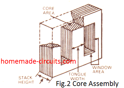
Now refer to Table#2 once again and as a final point find the appropriate core size, having adequate window area and a nearby value of the tongue width as calculated. Modify thel stack height as needed to acquire the intended core section.
Stack Height = Gross Core Area / Actual Tongue Width
The stack must not be a lot under the tongue width rather should be more. However, it must not be greater than 11/2 times the tongue width.
Core Assembly Diagram
How to Assemble the Transformer
The winding are done over an insulating former or bobbin that fits on the middle pillar of the core lamination.
The primary is generally wound first, and next it is the secondary, keeping an insulation between the two layers of the winding.
One last insulating layer is applied on top of the winding to safeguard all of them from mechanical and vibration deterioration.
Whenever thin wires are employed, their particular ends needs to be soldered to heavier wires in order to bring the terminals outside the former.
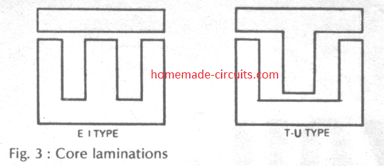
The lamination are usually put together on the former by alternate lamination reversed in set up.
The lamination has to be tightly bound together through an appropriate clamping framework or by using nuts and bolts (in case through holes are supplied within the lamination assembly).
How to Apply Shielding
This can be a wise idea to utilize an electrostatic shielding between the primary and secondary winding to circumvent electrical interference from moving across to the secondary from the primary.
The shield for step down transformers can be constructed from a copper foil which can be wound between the two winding for somewhat more than a tum.
Insulation has to be presented across the entire foil and proper care taken in order that the two ends of the foil never come in contact with each other.
Additionally a wire could be soldered with this shielding field and connected with the ground line of the circuit or with the lamination of the transformer which may be clamped with the ground line of the circuit.
For Torroidal Transformer designing, you can refer to the following pdf document:
https://www.homemade-circuits.com/wp-content/uploads/2021/04/torroidal-transformer_compressed.pdf
Additional Useful Information Regarding Transformer Winding
The following useful data related to transformer winding was kindly shared by Mr. Constantinos Mermygas. I hope the readers will find it very helpful.
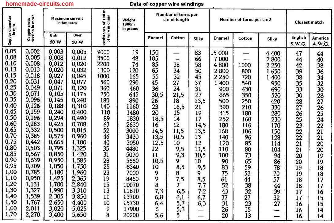
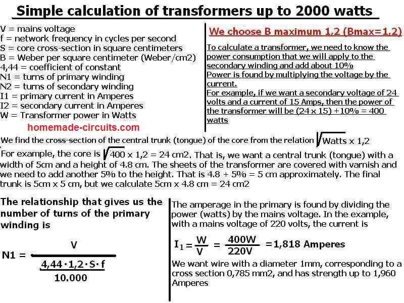
Simple Calculation of Transformers Up to 2000 Watts
Parameters:
- V = Mains voltage
- f = Network frequency in cycles per second
- S = Core cross-section in square centimeters
- B = Weber per square centimeter (Weber/cm²)
- 4.44 = Coefficient of constant
- N1 = Turns of primary winding
- N2 = Turns of secondary winding
- I1 = Primary current in Amperes
- I2 = Secondary current in Amperes
- W = Transformer power in Watts
Calculation Notes:
- Choose Bmax = 1.2 (maximum flux density).
- To calculate a transformer, determine the power consumption on the secondary winding and add approximately 10%.
Power Calculation Example:
- Secondary Voltage: 24 volts
- Current: 15 Amps
- Transformer Power: (24 * 15) + 10% = 400 watts
Core Cross-Section Calculation:
- Example:
Core cross-section: √400 * 1.2 = 24 cm²
Central trunk (tongue): - Width = 5 cm
- Height = 4.8 cm
- Add 5% for varnish, total height ≈ 5 cm
Primary Winding Turns Calculation:
- Formula:
N1 = V / (4.44 × B × S × f / 10,000)
Primary Current Calculation:
- Formula:
I1 = W / V
Example:
I1 = 400W / 220V = 1.818 Amperes
Wire Calculation:
- Example:
- Wire Diameter: 1 mm
- Cross Section: 0.785 mm²
- Current Strength: Up to 1.960 Amperes


Questions & Answers
This is a very interesting topic especially for me thank you for that
But what in a case i have a transformer salvage from ups and i want to redesign it how do i go about the calculationt
Thanks and best regards
And as for the sinewave inverter using spwm i’m still on it when I’m done i will share the good news
thank you once more for help God bless you real good
Thank you Faith, for modifying a readymade transformer you may have to go in the reverse manner and first identify the core size and the other parameters then compare them with the values given in the respective tables and subsequently evaluate the wire sizes and the number of turns
hello friend long time
i looking circuit for water level for up tank and down tank
down tank is whit water and up is low level turn pump on and so
and what y think i use a automotive rele 30amp to turn a 3hp 220 water pump ?
hello cristian, you can use any set-reset circuit using IC or transistor, and use the “set” points at the bottom of the ground tank and use the “reset” points at the brim of the overhead tank, and wire the relay accordingly.
yes 220V/30 amp relay will work
i show this but not look ic model
the design is correct, may be the ICs are IC 555
This was useful.Hope you can make a similar post on ferrite core transformers and its switching supply circuits.
I am glad you liked it, if I happen to find the ferrite core formulas, will surely update it here…
Dear,
Now I’ve started to build my own transformers (i’m describing an IRON CORE trafo). First i considered this difficult and never knew how to do so. Previously i had to compensate someone in the field to build as per my specs.
Now I’ve cracked the way how to build my own only after seeing this page in your blog.
I’ve got the stamping and frame ordered from Lamington road, purchased varnish and other basic materials required to build the transformer.
Till date I’ve made just one successfully.
I calculated all the electrical parameters involved in its construction and now its been constructed and working properly.
That’s great Sherwin, I am glad you could do it so easily…keep up the good work
Hi Swag,
I got some microwave oven transformers. to rewind for battery charging / inverter purpose. I try to rewind this transformers secondary line 12-0- 12 my coil gauge was SWG 10 and I have rewinding it bifilar type finally I got
8v-08v coz no more space to wind.and its working perfect. on this way I have rewind several transformers with different gauge wires.
now my question is I know how much the voltage output from this transformer. but how to check how much ampere its giving. it is possible to check a transformers output current without connecting a load?
regards.
Hi Paaker, probably the only way to know is by connecting a correctly rated ammeter directly across the output wires of the transformer and check the measurement. Do it only for a couple of seconds, otherwise the transformer or the meter or both could start fuming.
fine.
its possible to make a Battery charger with this transformer( 8v-0v-8v) to charge 12V 150A battery? I thing my transformer is around 40-45A. coz the wire I use to wind it was SWG 10.
yes its possible. use the outer wire to get 16V, and then add a voltage regulator to stabilize at 14.2V
Fine,
can you please suggest me a perfect circuit for this purpose.
Regards.
Here’s a simplest design:
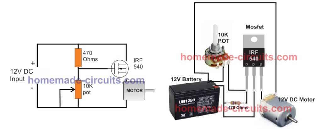
Replace the motor with a 1K resistor, adjust the pot to get exactly 14.2V across the 1K
That’s all…now you can connect your battery and let it charge until its terminals reach 14.2V.
For better protection connect a 0.3 ohm 25 watt resistor in series with the positive line, put this resistor over a large heatsink, and do the same to the mosfet also
teacher Swagatam I was reading your article on transformer calculations
now how do I know out put current when calculating core area per your calculations. 2 is this formula applicable to E and I transformers that handle 5Kw of power thanks teacher
Hello Osei, The formulas are applicable for 5 kW but the tables are not, they are limited to 10 amps max.
Thanks teacher Swagatam
Sir thanks for such a good circuit diagrams & details the one thing which is very important designing the transformer for SMPS Power supplies so sir is it possible to have some help from your side related to this topic as this is a very critical.
Hope to receive the reply.
Thanks & Regards
Thank you Dev, you can read the following post:
https://www.homemade-circuits.com/how-to-design-and-calculate-ferrite-core-transformers-for-inverters/
Good day sir, is it possible to wind like 10pcs of wire at same time for primary coil to make it faster and fewer number of turns and join end to start
Victory, the number of turns should be as per the calculations, adding more number of wires will increase the current handling capacity of the winding.
Hi Swag,
As they say the truth, in simple English, shall set you free. Thank you. This is the first clear discussion I see on trafo’s, especially the relationship between changed voltages and currents. I was particularly concerned about the effect of the changes in current in step-down trafo’s. One thing that became very clear is that I can imagine any situation and start from there. I can then practice the formula’s in every way possible to understand all the effects of all the different designs. This also gives me the ability to reverse engineer existing trafo’s and understand things even better.
Thank you, I like the way you explain things that I can follow your thinking. That makes it every easy to turn my own thinking onto something real.
Thanks Christo,
I am glad you found it useful…please keep up the good work!
I made a 78va capacity trafo inverter, i load it With 110w appliances, what may bẹ the effect technically.
Output voltage will drop proportionately
I saw a 1.5kva/24v inverter, the trafo guage amperage was 21.2amps for the battery side and the ac output sise was 2.64amps. please explain how it is so. For this inverter, it is suppose to be 55amps for the battery side which is not feasible
Pleas multiply the primary side voltage with its current, and the secondary side voltage with its current to get the wattages at the relevant sides of the trafo.
Hi swagtam. I used the turn per voltage formula and fixed these values: 1/(4.44*10^-4*50hz*528mm^2*1.1) giving me a total of 1/12.89376, equals 0.077556895turns per voltage, please help me calculate it using my values. The 528mm^2 is the core area, and i got it from tongue width: 1.6cm * tongue depth: 3.3cm. Please help me out
Hi Sam, we have solve it from top towards bottom, meaning start with current and the voltage of the primary and secondary and so on, it can be very difficult to do the opposite way.
Please swagtam what unit is there after the 1.152 in the core area formula, help me write it out in english, my phone displayed the unit as a tiny box (my phone cannot read the unit). Thanks for the previous reply.
Sam, That’s a square root symbol.
Thanks, and also swagtam i have an e core measuring 1.6cm tongue width and 3.3 tongue depth, i use the turn per volt formula and i get 8.53turns per volt but i think its wrong. Please help me calculate the turn per volt using my details, the frequency is 50hz, i just want to know if my answer is right. Please help me calculate it.
Hi Sam, This article is about iron-core step down transformer, it’s not for ecore.
Good day sir
What is the acceptable gap between the lamination of a transformer unit of a 630kva oil cooled minisub and the bottom of the tank, the voltage is 6600/550v
Good day Ceaser, sorry I have no idea about it…
What type of a transformer is used in a mosquito bat ? its a small black with yellow jacket around it.
It is a calculated ferrite core transformer. The calculation formulas are explained in this article:
https://www.homemade-circuits.com/how-to-design-and-calculate-ferrite-core-transformers-for-inverters/
Hi Swagatam,
I intend to build my own transformer winding Machine. I find it difficult to find plans to do this even on youtube. Could you perhaps suggest where I can get the necessary info.
Your assistance will be much appreciated.
Regards
Jan
Sorry Jan, presently I do not have any information regarding transformer winding machine. If I happen to find it I’ll surely update in my blog.
Thank you Swagatam
Hello Swag,
Sincerely appreciate gentlemen like you who help tinkerers like us! I just bought a kiln requiring 208volts and my service is 242volts. The kiln manufacturer tells me I can run the kiln, but the elements will fail prematurely, replacement cost for 240 elements is $700+. Would you be so kind as to help me create a drop down transformer either for each leg of 17 or so volts or in combo of about 32 volts, please? I can make the steel core parts and wind the whole thing by hand – I am very meticulous. Have more time than money! Hahahaha!!!! I am not the best at math so doing the calcs myself without guidance from a seasoned vet like you, would not be smart on my part. I don’t want to blow up the kiln I just invested $500 in. Thank you very much – in advance!
Thank you Ralph, A transformer based design may not be so appropriate since it will be bulky, difficult to calculate and prone to mistakes. The easiest and the ideal way to provide a controlled power to a kiln element or any resistive load is through a triac based phase chopper circuit as explained in the following article:
https://www.homemade-circuits.com/how-to-make-simplest-triac-flasher/
You can use any of the the last two designs for controlling your kiln element heat very efficiently and provide a long life to the element.
Hey Swag,
Greatly appreciate the speedy reply. I reviewed your recommendation and think the second design would be best with just a couple increments (resistors) rather than 4, but I have some concerns of which may or may not be warranted based on my limited knowledge on the subject… namely – “minimum transients and spikes” & “generation of lots of RF.” The kiln draws 53 amps and has a digital controller that ramps up temp, holding times, etc. Will there be varied voltages, RF emissions that interfere with the controller and are the components capable of handling 53 amps? Thank you!
Thanks Ralph, there will be RF emission when the load is operated with reduced power, and the Rf will decrease as the power on the load is increased using the potentiometer. However the L1, C1 is specifically to cancel these RF, so if these are correctly optimized, the RF emission can be expected to be minimum. The L1, C1 will also work to absorb spikes and transients.
53 amps looks very high, so the triac will need to be rated accordingly. Finding a 60 to 100 amp triacs is not easy, so this may be an issue.
To solve this a simpler design could be as shown below:
This design might also work as efficiently as one can expect. The bridge rectifier will also need to be rated at 60 to 100 amps
Hello again Swag, I contacted an electronic parts supply company, emailed the schematic you recommended and they replied:
“In order for us to locate a components on our website, please provide specification for each component on the diagram.”
So I called the tech support department and they said they need more information on the individual parts, their values, voltages, style of the caps, etc. I know I am asking a lot, but could I impose upon you for some detail on those components so the supply house can find them for me, please? Thank you.
Hello Ralph, In general when the part numbers are without specifications that suggests any variant and type can be used.
In this circuit, resistors can be 1/4 watt 5%, pot can be any 5K or 10K linear pot, capacitors can be ceramic disc type, MOSFETs can be IRF740 10nos in parallel.
Bridge rectifier should be 70 to 100 amp rated, IC can be any IC 555
Thank you so very much, really appreciate you going back and forth with on this. You are very kind!
It’s my pleasure, thanks!
Good afternoon Swag,
Hope you and yours are well.
Got all the components, but the 470R (its on the way). Unfortunately I am a bit confused as to how to actually make the connections. I am especially confused about how (which terminals) the two 120v legs from the panel connect to the Rectifier and then how the dropped voltage (104v) legs go back to the Kiln. The mosfet has three legs, it connects to the 470R – how? The G leg appears to be an output going to the load, but the load has two 104v legs required to run it? The 1K resistor connects to 4, 8 & +12volt AND pin 7 from the 555 IC? What about the negative12v leg – where does it connect? How does the 5K connect to the 1N4148, and pins 6 & 2, but how? I laid out the parts, lined them up and labeled them, took a picture of it, but don’t know how to attach it. Sorry about being such a neophyte, can’t get this wrong. BTW I have a couple pretty big heat sinks with fans to cool the rectifier and mosfet. And I’m using a computer 12v pwr supply. Thank you!!!
Hi Ralph,
the connections has to be exactly as shown in my previous diagram. (+) of the bridge goes to the load, the other leg of the load goes to the MOSFET drain. The bridge (-) and the 12V (-) must join as a common negative line, which is indicated as the 0V line in the diagram. So the -12V or the negative of the 12V must connect with the indicated 0V line of the circuit.
the pot center pin goes to pin6/2 o the IC, and the other outer pins go to the diodes.
Thank you Sir! I’m on it!
Hello yet again Swag,
You have been gracious with your time and information. I feel like I need to pay you for this and will if you wish… On the other hand, if I have “overstayed my welcome” on this forum, please simply don’t respond, I completely understand. Otherwise, I have just a couple final questions…
1. The S leg on the mosfet goes to 0V? What about B, the back of the mosfet, does that need to go to ground or should it be isolated? I will be mounting it to its own heatsink.
2. Does the pot dictate the voltage coming out of leg 3 of the IC, therefore determining the voltage coming out D leg of the Mosfet? Is there a tolerance for the pot?
3. Will the voltage going to the load, (one leg coming from D, on a 6AWG, and the other coming from the + side of the bridge also 6AWG), will each leg going to the load be around 104volts AC? The bridge will be mounted to a fan cooled heatsink, should the back be grounded or isolated?
4. Speaking from my VERY limited knowledge and pardon me for even questioning – but I don’t understand connecting the neg of the 12v pwr supply to the ground (0V) from the electrical panel. Could it just connect to the 100n at leg 5 of the IC or does it need the loop kinda thing? It must frustrate you dealing with neophytes like me. Sorry for troubling you with these questions, but thank you for helping.
Hello Ralph, I’ll try to answer your questions:
1) The back of the MOSFET can remain isolated from the supply lines. Only a heatsink may be clamped with the MOSFET back.
2) The pot adjusts the pulse widths of the pin 3 output pulses.
3) THe bridge output will be 104 AC x 1.41 = 146.64 V DC. The back of the bridge can also remain isolated if it has 4 individual legs on the other side.
4) You can connect the negative of 12V to any point of the shown 0V line.
Hello Devendra, i have a PCB related article posted in my website, you can find it here
https://www.homemade-circuits.com/how-to-make-pcb-at-home/
sir apka table no 1 16 ampear tak he ha 40 ampear ka liya kya kar kon swg wire and turn per square meter use kara
Dharnidhar, the range of the above calculation is 10 amp maximum only, 40 amp cannot be made using the above calculations
DEAR SIR TO HAM 18V-0-18V,40A PRIMARY TO 0-230V-600V AND 12V AC SECONDRY TRANSFORMER KAISE BANAEN
Sorry mere pass uska data nahi hai abhi. Ebay se readymade sample kharid kar check kar sakte ho.
DEAR SIR AAPKE PASS KOI FORMULA HAI JISSE KISI BHI TRANSFORMER KA DATA NIKALA JA SAKTA HAI
You can try this article for the basic formulas!
https://www.homemade-circuits.com/how-transformers-work/
hellow my friend , hope family doing well and taking care , I´m looking for good Zerner tester , to check the Volt if it could test up to 554 volt
thanks friend, I am good, presently I do not have the mentioned circuit, if possible I’ll try to update it in the coming days.
Very useful ideology
Sir,
Hope you’re doing well … !!!
In recent times i have reviewed couple of Youtube videos on HD Step Down Transformers Home Made, in most of the videos people show calculations in Inch. Where as in your article, shows in cm. When compared, process is similar, however formulas are different.
Finally when get SWG values from datasheet, in your article data sheet of SWG based on amp and Turns per Sq Cm, where as others mention, SWG based on Diameter of Inch, MM, MM2, kg/m
Concern is SWG and its values are different. So which one would you suggest to prefer. In most of the videos first we should find out Bobbin size and stack size of EI Core.
In your article, its all based on total power (Watts) and when we find out total winding area subjected to Primary and Secondary, we will find out from table and can know what would be EI core type for power.
So please tell, how come SWG values are differ.
Satish, it doesn’t matter how the units are calculated or which approach is used for designing the transformer, ultimately the number of turns and the thickness of the wire will be approximately the same for all the standard methods of calculations. The transformer dimension solely depends on the wattage, voltage and current of the transformer.
Hello Swagatam,
Thank this useful article. I have a small 110/220 volt transformer that I used as a step down transformer when I travel to a 220v country. I burnt this transformer one year ago by putting the 110v side into 220volts source. Now, after reading your article, I decided to rebuild the transformer using your knowledge. But I have a question, the transformer tag says it is 100 watts, core area is 2×2.5 cm. I used the formula Core Area: 1.152 x √P and found the manufacturer’s 100 watts is not correct.
Hello Abdul, yes the manufacturer normally do not provide the correct wattage, they always tend to put higher than the real values…
Is there any other simple way to design isolation transformer?
Dear sir, please sir, by means of measurement using a meter rule:
1. Is the Core Area = Tongue width x the short length of the center limb(i.e stack height) Or is the Core Area = Tongue width x the long length of the center limb?
2. Is the I – irons coupled with the E for determining the four measurements (i.e stack height, tongue width, window area and core area) Or is the four measurements determined only from the E – irons assembly?
The details are given in the following diagram, the parameters are exactly as shown in the image:
Yes sir, I saw the Core Assembly diagram already.
But I was unable to figure out which and which length of the center limb of the core makes up the Core Area, since you have not indicated using arrows like that of stack height, tongue width and window area.
So please sir, clarify this for me please:
Is the Core Area = tongue width x the long length of the center limb?
Or is it
Tongue width x the short length of the center limb (which can be imaged as stack height)?
Please sir, the reason I ask the question is that I have a stabilizer(automatic voltage regulator) transformer I want to disassemble and make new windings on it to become inverter transformer.
Please sir, the other thing I asked you was :
If the I – irons is included in the Core Assembly diagram for the four measurements (i.e core area, stack height, window area and tongue width)
Or it is only E – irons?
Please sir, clarify this for me. Thank you very much.
Godfrey, the core area = tongue width x stack height, or simply the L x B of the central pillar of the E-core.
The dimensions of the I iron laminations will be exactly as per the E-core lamination and cross section, as shown below:
Hi every1!
I’m looking for thoose sheets to build a transformer,
-where can i order such?
…without “minimum order: 1 ton / 2000 lbs.”
Thanks!
Okay sir, thank you very much sir.
Please sir, in other words, can the L x B of the bobbin be taken as core area?
Again, Please sir, am still confused of this point:
For an inverter with 230/12-0-12V, 10A transformer
Is the inverter power rating = 12 x 10 = 120VA or 24 x 10 = 240VA?
Thank you very much sir for your time.
Hello Godfrey, the transformer current rating provides the information regarding the output current of the unit, which is usually the stepped-down voltage side, so for your example it will be 12 x 10 = 120 watts.
One of the best websites for DIY transformer. I really thank you. People like you make a big difference.
Thank you very much, glad the post helped you!
Very informative and to the point. Well done God bless you though you are already blessed. You make a difference.
Thank you for kind feedback!
I have been looking for a way to create a 12VDC to 6VAC 2A output via a full isolation (voltage only – RFI passing is OK) transformer for over 10 years now and some may have have seen my requests in various circuit online offerings for going on this long. No takers yet. Seems simple but must be a catch. There are not even any low-voltage DC to AC buck converter devices I can find on eBay, Ali, etc. so it must be that I have to make my own. (Seems a crime to use an inefficient and loss-full 12VDC to 120AC inverter to power a wall adapter that outputs 6VAC with 2A maximum output, particularly when solar and 12VDC is my only available power source, and with only 400W of solar providing all individual daily electrical needs.) And while the 12VDC to 120VAC to 120VAC to 6VAC conversion with commercially available equipment has significantly more phantom load when not charging than the 2mA one would assume using a conventional DC to DC buck converter for some DC need. The level of help I am looking for e.g. if there are no commercial transformers for this project, I could wind one, what is the shell of transformer I should order and how many wraps of what gauge wire. Also what is a good 555 and couple of MosFETs perhaps in a push pull at around 60Hz that seem to be a good solution? I think this project is sort of a “contrary to everything” need because most power transfers demand much more efficient use of toroid coils and high speed switching circuits and this one is a poky 60hz. There are many other factors where devices working at such speeds and voltages just aren’t needed that much these days and are thus of no day to day popular interest.
I have a transformer thats 12-0-12 I wound it so no voltage is produced at the 2 wires there is no 24 volt. Is that correct.
If you have applied the mains AC at the primary, and you are not getting any voltage at the secondary, then it is wrong
I tried to go in to more detail I am not building a step down, this is a inverter transformer. I got all done and it said I asked the same question. Thanks for your time.
Thank you for your time, I guess I should have stated I am working on a inverter transformer. The first time I wound it I started with two wires as the center tap. Then wound both wires together in the same direction. Now I have two ends and a center tap. I got 12 volts from one wire using the center tap then got 12 volts from the other lead and center tap. When I measured the two end and not the center tap I should have 24 volts. The no reading 0 volts. That what I saw and was told to do for a interverter transformer. Now I tried the other way doing one wire at a time and putting insulation between the two wires. Now I have 24 volts on the two leads and 12 volts one each side of the center tap. Which one is correct ? Of the two ways of winding. Thanks
24 V voltage across outer leads, and 12 V between the outer and the center tap is the correct result, and the correct winding.
Step down 220v to 12v
(1) Give turns per voltage 220v
(2)give turns per voltage 12v
when my stack is 12cm and my tongue 5cm
I am moving to Europe and I have several electric tool that I would like to use there.
The strongest tools are a miter saw and a worm drive circular saw, both using 13 amps at 110 volts, single fase, 60 herts. Italy has 220 volts, 55 herts electricity.
Is it possible to build a transformer to run a circuit sufficient to to use my tools?
Yes that’s definitely possible. The easiest way probably is to buy a 220 x 7 = 1540 watt transformer, check the resistance of the 220 V side, then remove the secondary side winding and replace it with a winding that’s identical to the 220V side, but with 50% less resistance than the 220V side. The thickness of the wire must two times more than that of the 220V side wire.
dear sir
I calculate low scale transformer as follow But in the this calculate don’t know amounts “K” & delta
1)- S=k * square (p) S is area & p is apparent power in terms of v.a For 100 to 500 watt transformers
2)- d=1.13 * (square(I/delta)) d is wire Diameter & I is current
Yours sincerely
Hello Mohammad, sorry I do not have any information about the formula suggested by you, so can’t help you with this.
Hello, first thanks very much for sharing your work, it is truly usefull, is there some book or paper i can find more about this subject?
You are welcome!, if you search online you may find many relevant information.
From this website you can also refer to the following article:
https://www.homemade-circuits.com/how-transformers-work/
Hi sir, can the above core area, turns per volt formula work extremely well will an ordinary iron core also?or just for crgo only?
Yes it can
Sir,
Good evening,
I have salvaged a transformer from an UPS. The wires from the transformer connected to the 12V battery are thicker(E72332 AWM 1015 12AWG 600V ,yellow and black.) Normally it is a step down transformer to charge 12V battery. In case of power failure it acts as a step up transformer to power the computer. The wires are thinner (LL34978 18AWG 600V , red and white). Why?
It further says core is not earthed, risk of shock. What does it mean?
Thanks for your help.
Vishwa, the side of the transformer which is rated at low voltage will always have thicker wires since it carries higher current, and oppositely the side which is rated at higher voltage will carry lower current and therefore will have thinner wires.
If you are using a 3 pin plug for the 220V mains side, then the earth pin should be usually connected to the core of the transformer to avoid any kind of shock.
Sir,
Good afternoon,
Got it. Thanks a lot for your prompt reply.
Regards,
Vishwa Mukh Bharadwaj